EP0452285A1 - Procédé et dispositif pour mesurer automatiquement l'heure de départ pour l'évaporation d'un dispositif getter de baryum - Google Patents
Procédé et dispositif pour mesurer automatiquement l'heure de départ pour l'évaporation d'un dispositif getter de baryum Download PDFInfo
- Publication number
- EP0452285A1 EP0452285A1 EP91830143A EP91830143A EP0452285A1 EP 0452285 A1 EP0452285 A1 EP 0452285A1 EP 91830143 A EP91830143 A EP 91830143A EP 91830143 A EP91830143 A EP 91830143A EP 0452285 A1 EP0452285 A1 EP 0452285A1
- Authority
- EP
- European Patent Office
- Prior art keywords
- temperature
- getter
- start time
- barium
- fact
- Prior art date
- Legal status (The legal status is an assumption and is not a legal conclusion. Google has not performed a legal analysis and makes no representation as to the accuracy of the status listed.)
- Withdrawn
Links
- 229910052788 barium Inorganic materials 0.000 title claims abstract description 25
- DSAJWYNOEDNPEQ-UHFFFAOYSA-N barium atom Chemical compound [Ba] DSAJWYNOEDNPEQ-UHFFFAOYSA-N 0.000 title claims abstract description 25
- 230000008020 evaporation Effects 0.000 title claims abstract description 18
- 238000001704 evaporation Methods 0.000 title claims abstract description 18
- 238000005259 measurement Methods 0.000 title claims abstract description 13
- 238000000034 method Methods 0.000 title claims abstract description 11
- 239000011521 glass Substances 0.000 claims abstract description 13
- 238000010438 heat treatment Methods 0.000 claims description 14
- 230000006698 induction Effects 0.000 claims description 12
- 239000000523 sample Substances 0.000 claims description 3
- 230000003321 amplification Effects 0.000 claims 1
- 238000009795 derivation Methods 0.000 claims 1
- 230000004069 differentiation Effects 0.000 claims 1
- 230000010354 integration Effects 0.000 claims 1
- 238000003199 nucleic acid amplification method Methods 0.000 claims 1
- 239000000919 ceramic Substances 0.000 description 3
- 238000006243 chemical reaction Methods 0.000 description 3
- 238000004519 manufacturing process Methods 0.000 description 3
- 229910016015 BaAl4 Inorganic materials 0.000 description 2
- 230000000694 effects Effects 0.000 description 2
- 239000000463 material Substances 0.000 description 2
- 230000009467 reduction Effects 0.000 description 2
- OKTJSMMVPCPJKN-UHFFFAOYSA-N Carbon Chemical compound [C] OKTJSMMVPCPJKN-UHFFFAOYSA-N 0.000 description 1
- PXHVJJICTQNCMI-UHFFFAOYSA-N Nickel Chemical compound [Ni] PXHVJJICTQNCMI-UHFFFAOYSA-N 0.000 description 1
- 239000000956 alloy Substances 0.000 description 1
- 229910045601 alloy Inorganic materials 0.000 description 1
- 238000009529 body temperature measurement Methods 0.000 description 1
- 239000011248 coating agent Substances 0.000 description 1
- 238000000576 coating method Methods 0.000 description 1
- 230000008878 coupling Effects 0.000 description 1
- 238000010168 coupling process Methods 0.000 description 1
- 238000005859 coupling reaction Methods 0.000 description 1
- 230000003247 decreasing effect Effects 0.000 description 1
- 238000007872 degassing Methods 0.000 description 1
- 238000010586 diagram Methods 0.000 description 1
- 239000006185 dispersion Substances 0.000 description 1
- 229910002804 graphite Inorganic materials 0.000 description 1
- 239000010439 graphite Substances 0.000 description 1
- 238000009533 lab test Methods 0.000 description 1
- 230000008018 melting Effects 0.000 description 1
- 238000002844 melting Methods 0.000 description 1
- 239000000203 mixture Substances 0.000 description 1
- 238000013021 overheating Methods 0.000 description 1
- 239000000843 powder Substances 0.000 description 1
- 238000007789 sealing Methods 0.000 description 1
- 238000004904 shortening Methods 0.000 description 1
- 239000010409 thin film Substances 0.000 description 1
- 238000012546 transfer Methods 0.000 description 1
- 238000001429 visible spectrum Methods 0.000 description 1
- 230000000007 visual effect Effects 0.000 description 1
Images

Classifications
-
- H—ELECTRICITY
- H01—ELECTRIC ELEMENTS
- H01J—ELECTRIC DISCHARGE TUBES OR DISCHARGE LAMPS
- H01J9/00—Apparatus or processes specially adapted for the manufacture, installation, removal, maintenance of electric discharge tubes, discharge lamps, or parts thereof; Recovery of material from discharge tubes or lamps
- H01J9/38—Exhausting, degassing, filling, or cleaning vessels
- H01J9/39—Degassing vessels
Definitions
- the present invention relates to a method and device for the automatic measurement of the evaporation time of a barium getter.
- evaporable getter devices that are mounted within an evacuated electron tube, generally near to the glass wall, have to be evaporated before use.
- the evaporation takes place when, generally, the tube has been evacuated and tipped-off.
- Evaporation of the evaporable getter device takes place by heating the device to a temperature such that the barium contained therein is freed, in the form of vapours, which then deposits in the form of a thin film on surfaces within the tube.
- start time or time when barium starts to evaporate there is meant the time interval in seconds between the application of heating power and the onset of barium evaporation when there is the start of "flashing" due to onset of the exothermic reaction which is responsible for barium evaporation.
- the method according to the present invention is based on the measurement of the temperature on the external face of the wall of the vacuum tube corresponding to, and coaxial with, said induction heating coil by means of an infra-red pyrometer working at a wavelength of about 10 ⁇ m capable of measuring temperatures in an interval from 0°C to 500°C. From these measurements a temperature curve is obtained which reflects the trend of the getter temperature. The start of flashing corresponds to a temperature increase, ⁇ T, which results from many experimental observations. The temperature difference is made to correspond to a voltage value which can be used to make a real time automatic control of the R.F. generator feeding the induction coil; both the power level and the total time of the heating process can be controlled.
- Another object of the present invention is to provide an apparatus capable of carrying out the method described above in an automatic manner at a relatively low cost.
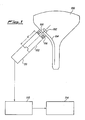
- FIG. 1 With reference to Fig. 1 there is shown a diagrammatic representation of a colour television kinescope 100 containing an evaporable barium getter device 102, mounted on an antenna spring 104 near to glass wall 105 of kinescope 100 and within its cone portion.
- Getter device 102 may be provided with a ceramic support which behaves as a separator between the container of getter device 102 and wall 105 of kinescope 100.
- an induction heating coil 106 for heating the getter material as is known in the art.
- the temperature on the outside of wall 105 is measured by means of a probe 108 of a sensor 110 which is preferably an infra-red pyrometer working at a wavelength suitable for measuring temperatures between 0°C and 500°C which include those measured on the outside glass wall corresponding to the position of the getter device. It is preferred to use an infra-red wave length as far away as possible from the visible spectrum such as 10 ⁇ m.
- sensor 110 the temperature increase or ⁇ T measured is transformed into a ⁇ V.
- ⁇ V can be fed to the input of an amplifier 112 to pilot a control logic circuit 114 which can directly control the power supplied to coil 106, so closing (not shown) a feedback circuit through which it is possible to regulate, in real time, the barium evaporation from getter device 102.
- Figure 2 shows the behaviour of temperature with time measured on a getter device heated by induction coil 106. It is seen that there is an initial continuous increase in temperature up to a value of about 800°C whereupon an exothermic reaction starts within the getter material resulting in a sudden increase in temperature and so a discontinuity of the curve.
- the reaction causes evaporation of barium according to: BaAl4 + 4Ni ⁇ Ba + 4NiAl where BaAl4 is a known alloy commonly used in barium getters as a powder, in mixture with nickel powder, in compressed form.
- the time corresponding to the temperature increase is the "start time” which normally varies from about 8 seconds to 15 seconds which is equal to the delay between the start of induction and the start of barium evaporation.
- the total time of application of the induction heating has a duration of about 30-40 seconds and corresponds to a point of now decreasing temperature.
- the importance has been shown of knowing the start time in order to ensure a good barium yield by suitably varying, for example, the total time of evaporation of the induction coil, or increasing the power applied but avoiding melting of the container due to too short a start time which can be overcome by shortening the total heating time or reducing the R.F. power.
- the graph represented in figure 3 which shows the temperature measured by device 108, 110 on the external portion of glass wall 105, is substantially the integral of the curve shown in figure 2.
- the initial temperature, T o of the kinescope indicated in figure 3 is higher than that of the getter in figure 2 which is normal due to the preliminary kinescope degassing treatment and sealing.
- the time corresponding to temperature T1 determines the start time or time of start of barium evaporation.
- ⁇ T is calculated from previous laboratory experiments by analyzing a series of curves made using kinescopes provided with a window in the "Dag".
- the value of ⁇ T depends, naturally, on the thickness and type of glass employed, on the thickness of the "Dag” as well as on the type of getter support (the presence or otherwise of ceramic) and remains constant for an extremely large number of kinescopes in mass production.
- the working conditions must be maintained reasonably constant for example the probe 108 must remain perfectly coaxial with getter device 102 and with coil 106, the sensor 110 is maintained at a distance of 30 cm from coil 106 and the temperature of the external surface of the kinescope is less than 70°C.
Landscapes
- Engineering & Computer Science (AREA)
- Manufacturing & Machinery (AREA)
- Manufacture Of Electron Tubes, Discharge Lamp Vessels, Lead-In Wires, And The Like (AREA)
Applications Claiming Priority (2)
| Application Number | Priority Date | Filing Date | Title |
|---|---|---|---|
| IT19988A IT1241102B (it) | 1990-04-11 | 1990-04-11 | Metodo ed apparecchiatura per la rilevazione automatica del tempo di evaporazione dei dispositivi getters al bario |
| IT1998890 | 1990-04-11 |
Publications (1)
| Publication Number | Publication Date |
|---|---|
| EP0452285A1 true EP0452285A1 (fr) | 1991-10-16 |
Family
ID=11162886
Family Applications (1)
| Application Number | Title | Priority Date | Filing Date |
|---|---|---|---|
| EP91830143A Withdrawn EP0452285A1 (fr) | 1990-04-11 | 1991-04-10 | Procédé et dispositif pour mesurer automatiquement l'heure de départ pour l'évaporation d'un dispositif getter de baryum |
Country Status (4)
| Country | Link |
|---|---|
| US (1) | US5139452A (fr) |
| EP (1) | EP0452285A1 (fr) |
| JP (1) | JPH04230932A (fr) |
| IT (1) | IT1241102B (fr) |
Families Citing this family (2)
| Publication number | Priority date | Publication date | Assignee | Title |
|---|---|---|---|---|
| JP3404807B2 (ja) * | 1993-06-30 | 2003-05-12 | ソニー株式会社 | ゲッター内蔵真空管の製造方法 |
| JP2004531042A (ja) * | 2001-06-27 | 2004-10-07 | コーニンクレッカ フィリップス エレクトロニクス エヌ ヴィ | 真空管のゲッタ材料を蒸発させるための方法及びその装置 |
Citations (3)
| Publication number | Priority date | Publication date | Assignee | Title |
|---|---|---|---|---|
| US4445872A (en) * | 1982-01-18 | 1984-05-01 | Rca Corporation | Method of detecting the vaporization of getter material during manufacture of a CRT |
| EP0187576A1 (fr) * | 1984-12-07 | 1986-07-16 | Videocolor | Procédé et appareil pour la détection de l'évaporation du matériau de getter au cours de la fabrication d'un tube cathodique, notamment pour la télévision |
| EP0321041A1 (fr) * | 1987-12-16 | 1989-06-21 | Koninklijke Philips Electronics N.V. | Dispositif de sorption par getter muni d'un détecteur de getter et d'une minuterie de postchauffage |
Family Cites Families (2)
| Publication number | Priority date | Publication date | Assignee | Title |
|---|---|---|---|---|
| JPS60143546A (ja) * | 1983-12-29 | 1985-07-29 | Nec Kansai Ltd | ゲツタ−フラツシユ方法 |
| US4820223A (en) * | 1988-06-02 | 1989-04-11 | Rca Licensing Corp. | System and method for monitoring spot-knocking of CRTs |
-
1990
- 1990-04-11 IT IT19988A patent/IT1241102B/it active IP Right Grant
-
1991
- 1991-04-10 JP JP3103633A patent/JPH04230932A/ja not_active Withdrawn
- 1991-04-10 EP EP91830143A patent/EP0452285A1/fr not_active Withdrawn
- 1991-04-11 US US07/683,613 patent/US5139452A/en not_active Expired - Fee Related
Patent Citations (3)
| Publication number | Priority date | Publication date | Assignee | Title |
|---|---|---|---|---|
| US4445872A (en) * | 1982-01-18 | 1984-05-01 | Rca Corporation | Method of detecting the vaporization of getter material during manufacture of a CRT |
| EP0187576A1 (fr) * | 1984-12-07 | 1986-07-16 | Videocolor | Procédé et appareil pour la détection de l'évaporation du matériau de getter au cours de la fabrication d'un tube cathodique, notamment pour la télévision |
| EP0321041A1 (fr) * | 1987-12-16 | 1989-06-21 | Koninklijke Philips Electronics N.V. | Dispositif de sorption par getter muni d'un détecteur de getter et d'une minuterie de postchauffage |
Non-Patent Citations (2)
| Title |
|---|
| PATENT ABSTRACTS OF JAPAN, unexamined applications, E field, vol. 10, No. 87, April 5, 1986; THE PATENT OFFICE JAPANESE GOVERNMENT, page 61 E 393 * |
| SOVIET INVENTIONS ILLUSTRATED, EL section, week 8442, November 28, 1984 DERWENT PUBLICATIONS LTD., London, V 05 * |
Also Published As
| Publication number | Publication date |
|---|---|
| IT9019988A1 (it) | 1991-10-11 |
| US5139452A (en) | 1992-08-18 |
| IT1241102B (it) | 1993-12-29 |
| JPH04230932A (ja) | 1992-08-19 |
| IT9019988A0 (it) | 1990-04-11 |
Similar Documents
| Publication | Publication Date | Title |
|---|---|---|
| DE69017247T2 (de) | Vorrichtung und Verfahren zur Infrarot-Thermometrie. | |
| DE68928305T2 (de) | Klinisches Strahlungsthermometer | |
| EP1440750B1 (fr) | Dispositif pour régler un procédé de coulée et de fusion | |
| DE69126885T3 (de) | Kalibrierung eines infrarot-thermometers mittels flächenhafter eichkurven-darstellung | |
| DE69519872T2 (de) | Verfahren zum einschätzen der temperatur im innern von einem zu kochenden produkt und thermisches kochgerät dafür | |
| EP0786649B1 (fr) | Thermomètre électronique à infrarouge et procédé de mesure de la température | |
| DE69231396T2 (de) | Verfahren und Vorrichtung für eine präzise Temperaturmessung | |
| US4980905A (en) | X-ray imaging apparatus dose calibration method | |
| EP1166067A1 (fr) | Thermometre a infrarouges comportant une pointe de mesure et un capuchon de protection pouvant chauffer | |
| Falk et al. | Time-dependent temperature distribution of graphite-tube atomizers | |
| CA1297166C (fr) | Methode et dispositif pour joindre des pieces en matiere ceramique par recours aux micro-ondes | |
| DE4243597C2 (de) | Mikrowellenleistungs-Erfassungsvorrichtung | |
| CA1268522A (fr) | Detecteur thermometrique, four a micro-ondes equipe dudit detecteur et methode de correction des donnees fournies par celui-ci | |
| EP0452285A1 (fr) | Procédé et dispositif pour mesurer automatiquement l'heure de départ pour l'évaporation d'un dispositif getter de baryum | |
| US3377838A (en) | Apparatus for measuring various transformation characteristics of metallic materials | |
| DE2449275B2 (de) | Vorrichtung zum ziehen eines kristalls aus einer schmelze | |
| DE308593T1 (de) | Verfahren und vorrichtung zur verbindung von gegenstaenden aus nichtoxidkeramik mittels mikrowellen. | |
| US3925665A (en) | Thermoluminescence Dosimeter Reader | |
| US5906766A (en) | Method for dielectrically heating an adhesive | |
| US4489236A (en) | Method for calibrating scintillation crystal | |
| US6730351B2 (en) | Method and apparatus for forming light absorption film | |
| US3981196A (en) | Apparatus for temperature measurement | |
| US4290182A (en) | Methods and apparatus for measuring the temperature of a continuously moving strand of material | |
| EP2005129A1 (fr) | Procédé et dispositif de thermométrie sans contact | |
| US4471265A (en) | Apparatus for counteracting the cathode current increase occurring during warming-up in a travelling-wave tube in response to variation in the grid-cathode distance |
Legal Events
| Date | Code | Title | Description |
|---|---|---|---|
| PUAI | Public reference made under article 153(3) epc to a published international application that has entered the european phase |
Free format text: ORIGINAL CODE: 0009012 |
|
| AK | Designated contracting states |
Kind code of ref document: A1 Designated state(s): DE FR GB NL |
|
| 17P | Request for examination filed |
Effective date: 19920328 |
|
| 17Q | First examination report despatched |
Effective date: 19940310 |
|
| STAA | Information on the status of an ep patent application or granted ep patent |
Free format text: STATUS: THE APPLICATION HAS BEEN WITHDRAWN |
|
| 18W | Application withdrawn |
Withdrawal date: 19940509 |