EP0187576A1 - Procédé et appareil pour la détection de l'évaporation du matériau de getter au cours de la fabrication d'un tube cathodique, notamment pour la télévision - Google Patents
Procédé et appareil pour la détection de l'évaporation du matériau de getter au cours de la fabrication d'un tube cathodique, notamment pour la télévision Download PDFInfo
- Publication number
- EP0187576A1 EP0187576A1 EP85402415A EP85402415A EP0187576A1 EP 0187576 A1 EP0187576 A1 EP 0187576A1 EP 85402415 A EP85402415 A EP 85402415A EP 85402415 A EP85402415 A EP 85402415A EP 0187576 A1 EP0187576 A1 EP 0187576A1
- Authority
- EP
- European Patent Office
- Prior art keywords
- cathode
- tube
- pressure
- getter material
- grid
- Prior art date
- Legal status (The legal status is an assumption and is not a legal conclusion. Google has not performed a legal analysis and makes no representation as to the accuracy of the status listed.)
- Granted
Links
- 239000000463 material Substances 0.000 title claims abstract description 24
- 238000004519 manufacturing process Methods 0.000 title claims abstract description 18
- 238000000034 method Methods 0.000 title claims abstract description 15
- 230000008016 vaporization Effects 0.000 title 1
- 238000009834 vaporization Methods 0.000 title 1
- 239000010406 cathode material Substances 0.000 claims abstract description 15
- 238000001704 evaporation Methods 0.000 claims abstract description 13
- 230000008020 evaporation Effects 0.000 claims abstract description 13
- 229910052788 barium Inorganic materials 0.000 claims abstract description 10
- DSAJWYNOEDNPEQ-UHFFFAOYSA-N barium atom Chemical compound [Ba] DSAJWYNOEDNPEQ-UHFFFAOYSA-N 0.000 claims abstract description 10
- 230000006641 stabilisation Effects 0.000 claims abstract description 9
- 238000011105 stabilization Methods 0.000 claims abstract description 9
- 239000008188 pellet Substances 0.000 claims abstract description 4
- 150000002500 ions Chemical class 0.000 claims description 16
- 238000007872 degassing Methods 0.000 claims description 8
- 230000015572 biosynthetic process Effects 0.000 claims description 6
- 238000011282 treatment Methods 0.000 claims description 5
- 238000009530 blood pressure measurement Methods 0.000 claims 1
- 238000010438 heat treatment Methods 0.000 description 7
- 230000006698 induction Effects 0.000 description 5
- 238000005259 measurement Methods 0.000 description 5
- 230000004913 activation Effects 0.000 description 4
- 239000007789 gas Substances 0.000 description 4
- 238000010586 diagram Methods 0.000 description 3
- 239000011521 glass Substances 0.000 description 3
- 230000000007 visual effect Effects 0.000 description 3
- CURLTUGMZLYLDI-UHFFFAOYSA-N Carbon dioxide Chemical compound O=C=O CURLTUGMZLYLDI-UHFFFAOYSA-N 0.000 description 2
- PXHVJJICTQNCMI-UHFFFAOYSA-N Nickel Chemical compound [Ni] PXHVJJICTQNCMI-UHFFFAOYSA-N 0.000 description 2
- 230000032683 aging Effects 0.000 description 2
- 230000007547 defect Effects 0.000 description 2
- VNWKTOKETHGBQD-UHFFFAOYSA-N methane Chemical compound C VNWKTOKETHGBQD-UHFFFAOYSA-N 0.000 description 2
- UGFAIRIUMAVXCW-UHFFFAOYSA-N Carbon monoxide Chemical compound [O+]#[C-] UGFAIRIUMAVXCW-UHFFFAOYSA-N 0.000 description 1
- BRPQOXSCLDDYGP-UHFFFAOYSA-N calcium oxide Chemical class [O-2].[Ca+2] BRPQOXSCLDDYGP-UHFFFAOYSA-N 0.000 description 1
- 235000012255 calcium oxide Nutrition 0.000 description 1
- 229910002092 carbon dioxide Inorganic materials 0.000 description 1
- 239000001569 carbon dioxide Substances 0.000 description 1
- 229910002091 carbon monoxide Inorganic materials 0.000 description 1
- 239000006185 dispersion Substances 0.000 description 1
- 238000000605 extraction Methods 0.000 description 1
- 239000000203 mixture Substances 0.000 description 1
- 229910052759 nickel Inorganic materials 0.000 description 1
- 239000002245 particle Substances 0.000 description 1
- 238000005086 pumping Methods 0.000 description 1
- 229910052712 strontium Inorganic materials 0.000 description 1
- CIOAGBVUUVVLOB-UHFFFAOYSA-N strontium atom Chemical compound [Sr] CIOAGBVUUVVLOB-UHFFFAOYSA-N 0.000 description 1
Images
Classifications
-
- H—ELECTRICITY
- H01—ELECTRIC ELEMENTS
- H01J—ELECTRIC DISCHARGE TUBES OR DISCHARGE LAMPS
- H01J9/00—Apparatus or processes specially adapted for the manufacture, installation, removal, maintenance of electric discharge tubes, discharge lamps, or parts thereof; Recovery of material from discharge tubes or lamps
- H01J9/42—Measurement or testing during manufacture
-
- H—ELECTRICITY
- H01—ELECTRIC ELEMENTS
- H01J—ELECTRIC DISCHARGE TUBES OR DISCHARGE LAMPS
- H01J7/00—Details not provided for in the preceding groups and common to two or more basic types of discharge tubes or lamps
- H01J7/14—Means for obtaining or maintaining the desired pressure within the vessel
- H01J7/18—Means for absorbing or adsorbing gas, e.g. by gettering
Definitions
- the invention relates to a method and an apparatus for detecting whether the getter material has been correctly evaporated during the manufacture of a cathode-ray tube, in particular color television.
- a cathode-ray tube is constituted by a vacuum glass vial with a front part forming a screen connected via a flared part to the cylindrical rear part, called the neck, at the end of which is housed the barrel (or the guns) with electrons.
- the electron gun of which a cup containing the getter material to be evaporated is attached, is installed in the bulb which is then emptied by pumping; then the getter material is evaporated by heating using an induction coil, after which the cathode (s) are heated to a temperature higher than the usual operating temperature in order to form and stabilize the material forming this cathode, and apply to the grids of the barrel voltages intended to clean the tube, that is to say to remove unwanted gaseous particles which are absorbed by the getter material.
- the tube thus produced will not be able to function correctly due, on the one hand, to the poor quality of the vacuum, and on the other hand, above all, to the presence of positive ions who will be attracted to and deteriorate the cathode.
- the invention overcomes these drawbacks.
- the pressure prevailing in the tube during the stabilization of the cathode material is measured and the tube is brought back to the getter material evaporation station if this pressure exceeds a predetermined value, for example 2 x 10 -4 Torr.
- a predetermined value for example 2 x 10 -4 Torr.
- a positive potential is applied to one of the electrodes, in particular the grid G 2 of the electron gun, and a negative potential on another electrode, for example the grid G 3 forming part of the electrostatic lens, and the intensity of the electric current flowing between the electrode brought to a negative potential and the mass is measured.
- This intensity represents the charge of positive ions in the tube and therefore the pressure.
- the intensity of the current flowing in the grid G 3 exceeds 150 nano-amps, which corresponds to a pressure of 2 x 10 - 4 Torr, if the material of the getter has not evaporated to spread on the walls of the tube and is of the order of 25 nanoamps - or 4 to 5 x 10 Tor otherwise.
- the tube being treated is thus brought back to the station for evaporation of the getter material if the intensity between the electrode G 3 and the mass exceeds 150 nano-amperes.
- the generator applying a positive potential on one of the electrodes is a constant current generator so that the intensity of the measurement current is not affected, or is little affected by the differences in characteristics between individual tubes, these differences or dispersions being inherent in mass production.
- the example which will be described relates to the manufacture of a color television tube of the shadow mask type.
- This getter material consists of a barium pellet placed in a cup 12 located in the conical or flared part 13 of the bulb 11 attached by a rod 14 to the envelope of the block 15 of electron guns.
- the heating of the barium with a view to its evaporation is carried out using an induction coil 16 arranged outside the bulb 11 but in the vicinity of the cup 12.
- the frequency and the power of the supply of the coil 16 are such that they make it possible to reach a temperature of this cup of between 800 and 1100 "C.
- This cathode 20 usually comprises a nickel tube and the electron-emitting material consists of a mixture of barium, strontium and calcium oxides.
- the heating filament 21 for heating the latter is brought to a temperature higher than that of normal operation.
- the formation, or activation, of the cathode is carried out for a period of duration approximately 4 minutes; this activation period is itself divided into two stages of roughly equal durations: during the first the cathode material is brought to a temperature of approximately 1000 ° C. and during the second step this material is brought at a higher temperature, of the order of 1070 ° C.
- the cathode material is stabilized for approximately 14 minutes. During this stabilization the cathode material is brought to a temperature of approximately 1000 ° C.
- gases such as carbon monoxide CO, carbon dioxide C0 2 , methane CH 4 , etc ... These gases contain in equal proportions, from the electrical point of view, positive ions and negative ions.
- Positive (+) ions are particularly harmful to the cathode because, the latter being brought to a negative potential, it attracts positive charges, which risks damaging it.
- the getter material distributed over the walls of the bulb It absorbs the gases released both during the formation of the cathode material and during subsequent degassing treatments.
- the gas pressure in the tube is measured after the cathode material has been formed, during the period of stabilization of this material. This pressure is measured before the subsequent degassing or controlled aging operation. For this measurement, the charge of positive ions is determined. For this purpose, approximately 10 minutes after the start of activation of the cathode material, that is to say during the stabilization period, a positive potential is applied to the second grid 22, called G 2 , in connecting the latter to the positive potential terminal 25 of a constant current generator 24 and a negative potential is applied to the third grid 23, called G 3 , by connecting the negative terminal of a voltage generator 26 to this grid G 3 .
- the source 26 delivers a voltage of 22.5 volts in the example.
- a resistor 27 of value 100 K ⁇ for example is placed between the positive potential terminal of the source 26 and the ground.
- a voltmeter 28 is connected in parallel to this resistor 27.
- the voltage measured by this voltmeter represents the intensity of the current passing through the resistor 27, that is to say leaving the grid G 3 .
- the first grid, called G 1 is connected to ground, as is the cathode 20.
- the positive ions are attracted to the gate 23 brought to a negative potential, while the negative ions are attracted to the gate G 2 , 22, brought to a positive potential.
- the current - measured by the voltmeter 28 - flowing in the resistor 27 represents the charge in positive ions in the bulb 11 and therefore the total pressure.
- connection, to the respective grids, of the source 26 and of the generator 24 is effected by means of a socket 30 (FIG. 4), that which is usually used to make the connections for the formation of the cathode material and degassing treatments.
- the intensity i of the current in the resistor 27 varies as a function of time t as represented by the curve 31 (FIG. 3) in solid lines.
- the current has an intensity of the order of 300 nanoamps.
- this intensity has dropped to the value of 25 nano-amps.
- the tube is brought back to the induction heating station to evaporate the barium pellet.
- the intensity is less than 150 nanoamps, the tube remains on the production line to undergo the degassing treatment.
- the sleeve 30 is separated from the tube 10 but the latter remains on the production line with the other tubes until the end of the degassing treatment.
- the tube which does not include a socket 30 does not undergo either the end of the stabilization of the cathode material or the degassing or aging. In this example, the tube is brought back to the induction heating station after the degassing period which it has not, however, undergone.
- the comparison with the value of 150 nanoamps can be carried out by an operator. It is also possible to provide a comparator for delivering a signal when the intensity exceeds said predetermined value. This signal can activate visual or audible alarm means. This signal can also be used to control a socket extraction mechanism 30.
Landscapes
- Engineering & Computer Science (AREA)
- Manufacturing & Machinery (AREA)
- Manufacture Of Electron Tubes, Discharge Lamp Vessels, Lead-In Wires, And The Like (AREA)
Abstract
Description
- L'invention est relative à un procédé et à un appareil pour détecter si le matériau getter a été correctement évaporé au cours de la fabrication d'un tube cathodique, notamment de télévision en couleurs.
- Un tube cathodique est constitué par une ampoule de verre sous vide avec une partie frontale formant écran raccordée par l'intermédiaire d'une partie évasée à la partie arrière cylindrique, appelée col, à l'extrémité de laquelle est logé le canon (ou les canons) à électrons.
- Les dernières étapes de fabrication du tube sont les suivantes : le canon à électrons duquel est solidaire une coupelle contenant le matériau de getter à évaporer, est installé dans l'ampoule qu'on vide ensuite par pompage; puis on évapore le matériau getter par chauffage à l'aide d'une bobine d'induction, à la suite de quoi on chauffe la (ou les) cathode(s) à une température supérieure à la température habituelle de fonctionnement afin de former et stabiliser le matériau formant cette cathode, et on applique aux grilles du canon des tensions destinées à nettoyer le tube, c'est-à-dire à éliminer les particules gazeuses indésirables qui sont absorbées par le matériau getter. Si le matériau getter ne s'est pas évaporé, le tube ainsi réalisé ne pourra pas fonctionner correctement en raison, d'une part, de la mauvaise qualité du vide, et d'autre part, surtout, de la présence d'ions positifs qui seront attirés par la cathode et la détérioreront.
- On a constaté que sur les chaînes de fabrication en série pour environ 1 % des tubes l'évaporation du matériau de getter ne s'effectue pas correctement. Les tubes qui présentent ce défaut doivent alors être traités de nouveau, c'est-à-dire qu'ils doivent être dégagés de la chaîne de fabrication et ramenés au poste d'évaporation du getter. Cet incident peut avoir des causes diverses : erreur de l'opérateur, mauvais positionnement de la bobine utilisée pour le chauffage par induction en vue de l'évaporation, défaut de cette bobine ou de sa source d'alimentation, etc...
- Jusqu'à présent le contrôle de l'évaporation du matériau de getter s'effectue par observation visuelle des parois du tube. Un tel type de contrôle n'est pas entièrement fiable car un défaut d'évaporation peut ne pas être détecté par inattention de l'opérateur. En outre l'observation visuelle est pénible.
- L'invention remédie à ces inconvénients.
- Elle est caractérisée en ce qu'on mesure la pression régnant dans le tube au cours de la stabilisation du matériau de cathode et on ramène le tube au poste d'évaporation du matériau de getter si cette pression dépasse une valeur prédéterminée, par exemple 2 x 10⁻⁴ Torr. A cet effet, dans une réalisation particulièrement simple à mettre en oeuvre, on mesure la charge en ions positifs, seuls dangereux pour la cathode. Il pourrait aussi être envisagé de mesurer la charge en ions négatifs; mais cette mesure serait difficile à effectuer car, au cours de la stabilisation du matériau de la cathode, cette dernière produit des électrons et la charge provenant de ces électrons s'ajoute à celles des ions négatifs et ne peut pas en être séparée; de ce fait la charge négative mesurée ne représenterait pas correctement la pression dans le tube.
- Pour effectuer ladite mesure de charge en ions positifs, dans un exemple, on applique un potentiel positif à l'une des électrodes, notamment la grille G2 du canon à électrons, et un potentiel négatif sur une autre électrode, par exemple la grille G3 faisant partie de la lentille électrostatique, et on mesure l'intensité du courant électrique circulant entre l'électrode portée à un potentiel négatif et la masse. Cette intensité représente la charge en ions positifs dans le tube et donc la pression. Il est important de noter que, pour la mesure, on ne fait pas appel à la cathode; en effet si, sur cette dernière, on appliquait un potentiel négatif elle attirerait des ions positifs, ce qui l'endommagerait. Si le potentiel négatif appliqué sur l'électrode G3 est de - 22,5 V, on a constaté qu'après un temps de 10 à 15 minutes suivant la formation du matériau de cathode, l'intensité du courant circulant dans la grille G3 dépasse 150 nano- ampères, ce qui correspond à une pression de 2 x 10 - 4 Torr, si le matériau du getter ne s'est pas évaporé pour se répandre sur les parois du tube et est de l'ordre de 25 nanoampères - soit 4 à 5 x 10 Tor dans le cas contraire. Le tube en cours de traitement est ainsi ramené au poste d'évaporation du matériau de getter si l'intensité entre l'électrode G3 et la masse dépasse 150 nano- ampères.
- Il est préférable que le générateur appliquant un potentiel positif sur l'une des électrodes soit un générateur à courant constant afin que l'intensité du courant de mesure ne soit pas affectée, ou soit peu affectée par les différences de caractéristiques entre tubes individuels, ces différences ou dispersions étant inhérentes à la fabrication en grande série.
- D'autres caractéristiques et avantages de l'invention apparaîtront avec la description de certains de ses modes de réalisation, celle-ci étant effectuée en se référant aux dessins ci-annexés sur lesquels :
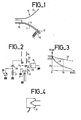
- - la figure 1 est un schéma d'une partie d'un tube cathodique lors de sa fabrication.
- - la figure 2 montre un canon à électrons d'un tube cathodique et des sources de courant et de tension utilisées pour mettre en oeuvre le procédé de l'invention,
- - la figure 3 est un diagramme expliquant le procédé de l'invention et,
- - la figure 4 est un schéma de la partie arrière d'un tube cathodique au cours d'une étape de sa fabrication.
- L'exemple que l'on va décrire se rapporte à la fabrication d'un tube de télévision en couleurs du type à masque d'ombre.
- Lors des dernières étapes de la fabrication d'un tube cathodique 10, juste après la mise sous vide de l'ampoule de verre 11, on procède à l'évaporation du matériau de getter afin qu'il soit réparti sur toutes les parois de verre. Ce matériau de getter est constitué par une pastille de baryum disposée dans une coupelle 12 se trouvant dans la partie cônique ou évasée 13 de l'ampoule 11 rattachée par une tige 14 à l'enveloppe du bloc 15 de canons à électrons.
- Le chauffage du baryum en vue de son évaporation est effectué à l'aide d'une bobine d'induction 16 disposée à l'extérieur de l'ampoule 11 mais au voisinage de la coupelle 12. La fréquence et la puissance de l'alimentation de la bobine 16 sont telles qu'elles permettent d'atteindre une température de cette coupelle comprise entre 800 et 1100" C.
- Après cette évaporation du baryum on procède à la formation et la stabilisation du matériau formant la cathode 20 (figure 2). Cette cathode 20 comporte habituellement un tube de nickel et le matériau d'émission des électrons est constitué par un mélange d'oxydes de baryum, de strontium et de calcium.
- Pour la formation et la stabilisation du matériau de cathode on porte le filament 21 de chauffage de cette dernière à une température supérieure à celle du fonctionnement habituel.
- La formation, ou activation, de la cathode est effectuée pendant une période de durée 4 minutes environ; cette période d'activation est elle-même divisée en deux étapes de durées à peu près égales : au cours de la première le matériau de cathode est porté à une température de 1000° C environ et au cours de la seconde étape ce matériau est porté à une température supérieure, de l'ordre de 1070° C.
- La stabilisation du matériau de cathode est effectuée pendant 14 minutes environ. Lors de cette stabilisation le matériau de cathode est porté à une température d'environ 1000° C. Au cours de ces étapes de la fabrication du tube il se dégage, dans ce dernier, en particulier lors de l'activation, des gaz tels que l'oxyde de carbone CO, l'anhydride de carbone C02, le méthane CH4, etc... Ces gaz contiennent en proportions égales, du point de vue électrique, des ions positifs et des ions négatifs. Les ions positifs (+) sont particulièrement nocifs pour la cathode car, celle-ci étant portée à un potentiel négatif, elle attire les charges positives, ce qui risque de la détériorer. le matériau de getter réparti sur les parois de l'ampoule Il absorbe les gaz dégagés tant lors de la formation du matériau de cathode que lors des traitements ultérieurs de dégazage.
- Pour contrôler que le baryum contenu dans la coupelle 12 a été correctement évaporé, selon l'invention, on mesure la pression de gaz dans le tube après la formation du matériau de cathode, au cours de la période de stabilisation de ce matériau. Cette pression est mesurée avant l'opération ultérieure de dégazage ou vieillissement contrôlé. Pour cette mesure on détermine la charge en ions positifs. A cet effet, environ 10 minutes après le début de l'activation du matériau de cathode, c'est-à-dire au cours de la période de stabilisation, on applique un potentiel positif sur la seconde grille 22, dite G2, en reliant cette dernière à la borne 25 de potentiel positif d'un générateur 24 de courant constant et on applique un potentiel négatif sur la troisième grille 23, dite G3, en reliant la borne négative d'un générateur de tension 26 à cette grille G3. La source 26 délivre une tension de 22, 5 Volts dans l'exemple.
- Entre la borne de potentiel positif de la source 26 et la masse est disposée une résistance 27 de valeur 100 KΩ par exemple. En parallèle sur cette résistance 27 est connecté un voltmètre 28. La tension mesurée par ce voltmètre représente l'intensité du courant traversant la résistance 27, c'est-à-dire sortant de la grille G3. Au cours de cette étape de contrôle de pression par mesure de la charge en ions positifs dans le tube, la première grille, dite G 1, est reliée à la masse, de même que la cathode 20.
- Les ions positifs sont attirés par la grille 23 portée à un potentiel négatif, tandis que les ions négatifs sont attirés vers la grille G2, 22, portée à un potentiel positif. Ainsi le courant - mesuré par le voltmètre 28 - circulant dans la résistance 27 représente la charge en ions positifs dans l'ampoule 11 et donc la pression totale.
- La connexion, aux grilles respectives, de la source 26 et du générateur 24 s'effectue par l'intermédiaire d'une douille 30 (figure 4), celle qui est habituellement utilisée pour effectuer les connexions en vue de la formation du matériau de cathode et des traitements de dégazage.
- Si le baryum a été correctement évaporé l'intensité i du courant dans la résistance 27 varie en fonction du temps t comme représenté par la courbe 31 (figure 3) en traits pleins. Tout de suite après la formation de la cathode, au temps t = 0, le courant a une intensité de l'ordre de 300 nanoampères. Au bout d'un temps de l'ordre de 10 minutes cette intensité est descendue à la valeur de 25 nano-ampères. Par contre si le baryum n'a pas été évaporé l'intensité i varie selon la courbe 32 en traits interrompus; au bout du temps t = 10 minutes environ, cette intensité a une valeur de l'ordre de 200 nanoampères.
- De cette manière si l'intensité i du courant dans la résistance 27 dépasse 150 nanoampères le tube est ramené au poste de chauffage par induction pour évaporer la pastille de baryum. Par contre si l'intensité est inférieure à 150 nanoampères, le tube reste sur la chaîne de fabrication pour subir le traitement de dégazage. Dans un exemple si l'intensité i du courant dépasse 150 nanoampères la douille 30 est séparée du tube 10 mais ce dernier reste sur la chaîne de fabrication avec les autres tubes jusqu'à la fin du traitement de dégazage. Mais le tube qui ne comporte pas de douille 30 ne subit ni la fin de la stabilisation du matériau de cathode ni le dégazage ou vieillissement. Dans cet exemple le tube est ramené au poste de chauffage par induction après la période de dégazage qu'il n'a cependant pas subie.
- La comparaison avec la valeur de 150 nanoampères peut être effectuée par un opérateur. On peut également prévoir un comparateur pour délivrer un signal lorsque l'intensité dépasse ladite valeur prédéterminée. Ce signal peut actionner des moyens d'alarme visuels ou sonores. Ce signal peut également être utilisé pour commander un mécanisme d'extraction de douille 30.
Claims (10)
Priority Applications (1)
| Application Number | Priority Date | Filing Date | Title |
|---|---|---|---|
| AT85402415T ATE43203T1 (de) | 1984-12-07 | 1985-12-04 | Verfahren und vorrichtung zur feststellung der gattermaterialverdampfung waehrend der herstellung einer kathodenstrahlroehre, insbesondere fuer das fernsehen. |
Applications Claiming Priority (2)
| Application Number | Priority Date | Filing Date | Title |
|---|---|---|---|
| FR8418777A FR2574590B1 (fr) | 1984-12-07 | 1984-12-07 | Procede et appareil pour la detection de l'evaporation du materiau de getter au cours de la fabrication d'un tube cathodique, notamment pour la television |
| FR8418777 | 1984-12-07 |
Publications (2)
| Publication Number | Publication Date |
|---|---|
| EP0187576A1 true EP0187576A1 (fr) | 1986-07-16 |
| EP0187576B1 EP0187576B1 (fr) | 1989-05-17 |
Family
ID=9310385
Family Applications (1)
| Application Number | Title | Priority Date | Filing Date |
|---|---|---|---|
| EP85402415A Expired EP0187576B1 (fr) | 1984-12-07 | 1985-12-04 | Procédé et appareil pour la détection de l'évaporation du matériau de getter au cours de la fabrication d'un tube cathodique, notamment pour la télévision |
Country Status (9)
| Country | Link |
|---|---|
| US (1) | US4668203A (fr) |
| EP (1) | EP0187576B1 (fr) |
| JP (1) | JPS61138434A (fr) |
| AT (1) | ATE43203T1 (fr) |
| DE (1) | DE3570323D1 (fr) |
| FR (1) | FR2574590B1 (fr) |
| HK (1) | HK102690A (fr) |
| IN (1) | IN166685B (fr) |
| SG (1) | SG78190G (fr) |
Cited By (1)
| Publication number | Priority date | Publication date | Assignee | Title |
|---|---|---|---|---|
| EP0452285A1 (fr) * | 1990-04-11 | 1991-10-16 | SAES GETTERS S.p.A. | Procédé et dispositif pour mesurer automatiquement l'heure de départ pour l'évaporation d'un dispositif getter de baryum |
Families Citing this family (2)
| Publication number | Priority date | Publication date | Assignee | Title |
|---|---|---|---|---|
| NL8703042A (nl) * | 1987-12-16 | 1989-07-17 | Philips Nv | Getterinrichting met een getterdetector en een naverwarmingstijdklok. |
| JP2962270B2 (ja) * | 1997-04-03 | 1999-10-12 | 日本電気株式会社 | 陰極線管の製造方法 |
Citations (3)
| Publication number | Priority date | Publication date | Assignee | Title |
|---|---|---|---|---|
| US2141644A (en) * | 1937-11-27 | 1938-12-27 | Rca Corp | Manufacture of evacuated metal envelopes |
| US3227506A (en) * | 1961-09-18 | 1966-01-04 | Rca Corp | Method of making electron tubes |
| US4445872A (en) * | 1982-01-18 | 1984-05-01 | Rca Corporation | Method of detecting the vaporization of getter material during manufacture of a CRT |
Family Cites Families (4)
| Publication number | Priority date | Publication date | Assignee | Title |
|---|---|---|---|---|
| US2861861A (en) * | 1951-11-13 | 1958-11-25 | Rca Corp | Gas pressure testing and control apparatus |
| JPS4874777A (fr) * | 1971-12-30 | 1973-10-08 | ||
| US4038616A (en) * | 1976-04-29 | 1977-07-26 | Rca Corporation | Vacuum tube gas test apparatus |
| JPS5574038A (en) * | 1978-11-29 | 1980-06-04 | Hitachi Ltd | Vacuum measuring device for picture tube |
-
1984
- 1984-12-07 FR FR8418777A patent/FR2574590B1/fr not_active Expired
-
1985
- 1985-12-04 US US06/804,597 patent/US4668203A/en not_active Expired - Fee Related
- 1985-12-04 DE DE8585402415T patent/DE3570323D1/de not_active Expired
- 1985-12-04 EP EP85402415A patent/EP0187576B1/fr not_active Expired
- 1985-12-04 AT AT85402415T patent/ATE43203T1/de not_active IP Right Cessation
- 1985-12-06 JP JP60274845A patent/JPS61138434A/ja active Pending
-
1986
- 1986-06-10 IN IN510/DEL/86A patent/IN166685B/en unknown
-
1990
- 1990-09-25 SG SG781/90A patent/SG78190G/en unknown
- 1990-12-06 HK HK1026/90A patent/HK102690A/xx unknown
Patent Citations (3)
| Publication number | Priority date | Publication date | Assignee | Title |
|---|---|---|---|---|
| US2141644A (en) * | 1937-11-27 | 1938-12-27 | Rca Corp | Manufacture of evacuated metal envelopes |
| US3227506A (en) * | 1961-09-18 | 1966-01-04 | Rca Corp | Method of making electron tubes |
| US4445872A (en) * | 1982-01-18 | 1984-05-01 | Rca Corporation | Method of detecting the vaporization of getter material during manufacture of a CRT |
Non-Patent Citations (1)
| Title |
|---|
| LE VIDE, no. 109, janvier-février 1964, pages 631-637, Paris, FR; P. MEYERER: "Etude de la pression limite pouvant être obtenue dans un tube à ondes progressives" * |
Cited By (1)
| Publication number | Priority date | Publication date | Assignee | Title |
|---|---|---|---|---|
| EP0452285A1 (fr) * | 1990-04-11 | 1991-10-16 | SAES GETTERS S.p.A. | Procédé et dispositif pour mesurer automatiquement l'heure de départ pour l'évaporation d'un dispositif getter de baryum |
Also Published As
| Publication number | Publication date |
|---|---|
| JPS61138434A (ja) | 1986-06-25 |
| IN166685B (fr) | 1990-06-30 |
| DE3570323D1 (en) | 1989-06-22 |
| FR2574590A1 (fr) | 1986-06-13 |
| US4668203A (en) | 1987-05-26 |
| ATE43203T1 (de) | 1989-06-15 |
| EP0187576B1 (fr) | 1989-05-17 |
| FR2574590B1 (fr) | 1988-05-13 |
| HK102690A (en) | 1990-12-14 |
| SG78190G (en) | 1991-01-18 |
Similar Documents
| Publication | Publication Date | Title |
|---|---|---|
| EP0051006A2 (fr) | Procédé et dispositifs pour transférer des charges électriques de signes différents dans une zone d'espace et application aux éliminateurs d'électricité statique | |
| EP0187576B1 (fr) | Procédé et appareil pour la détection de l'évaporation du matériau de getter au cours de la fabrication d'un tube cathodique, notamment pour la télévision | |
| US4395242A (en) | Method of electrically processing a CRT mount assembly to reduce afterglow | |
| EP0752716A1 (fr) | Dispositif d'amorçage et/ou de maintien d'une décharge et jauge à vide à cathode froide comportant un tel dispositif | |
| EP0362946A1 (fr) | Dispositif d'extraction et d'accélération des ions limitant la réaccélération des électrons secondaires dans un tube neutronique scellé à haut flux | |
| EP0340832B1 (fr) | Tube neutronique scellé, à haut flux | |
| US3434770A (en) | Reduction of arcing between the parts of a cathode ray tube | |
| Broadbent | The breakdown mechanism of certain triggered spark gaps | |
| US4125306A (en) | Spiked low-voltage aging of cathode-ray tubes | |
| FR2714208A1 (fr) | Cathode, canon à électrons comportant une telle cathode et tube à rayons cathodiques comportant un tel canon. | |
| EP0044239B1 (fr) | Tube intensificateur d'images à micro-canaux et ensemble de prise de vues comprenant un tel tube | |
| EP0040126B1 (fr) | Canon à électrons pour faisceau convergent | |
| Xu et al. | Electrical and spatial correlations between direct current pre-breakdown electron emission characteristics and subsequent breakdown events | |
| EP0206927B1 (fr) | Procédé de chauffage des électrodes d'un canon à électrons au cours de sa fabrication | |
| TWI223222B (en) | Procedures and apparatus for turning-on and turning-off elements within a fed device | |
| FR3013894A1 (fr) | Lampe eclair avec remplissage de gaz pour empecher un autoallumage | |
| US10605687B2 (en) | Spark gap device and method of measurement of X-ray tube vacuum pressure | |
| EP0130874A1 (fr) | Procédé et appareil de chauffage des électrodes ou lentilles électrostatiques d'un canon à électrons d'un tube à rayons cathodiques au cours de sa fabrication | |
| WO2014095888A1 (fr) | Dispositif d'optique electronique | |
| FR2886455A1 (fr) | Procede de reglage de la convergence statique sur un tube a rayons cathodiques couleurs | |
| BE427946A (fr) | ||
| FR2612637A1 (fr) | Procede et appareil pour detecter le percage d'un tube a rayons cathodiques | |
| FR3098341A1 (fr) | Generateur pulse de particules chargees electriquement et procede d’utilisation d’un generateur pulse de particules chargees electriquement | |
| FR3084472A1 (fr) | Capteur d'irradiation externe par les electrons et les photons | |
| Atkinson | Limiting currents and neutralization in cylindrical electron beams |
Legal Events
| Date | Code | Title | Description |
|---|---|---|---|
| PUAI | Public reference made under article 153(3) epc to a published international application that has entered the european phase |
Free format text: ORIGINAL CODE: 0009012 |
|
| AK | Designated contracting states |
Kind code of ref document: A1 Designated state(s): AT DE GB IT NL |
|
| 17P | Request for examination filed |
Effective date: 19860807 |
|
| 17Q | First examination report despatched |
Effective date: 19871119 |
|
| GRAA | (expected) grant |
Free format text: ORIGINAL CODE: 0009210 |
|
| AK | Designated contracting states |
Kind code of ref document: B1 Designated state(s): AT DE GB IT NL |
|
| PG25 | Lapsed in a contracting state [announced via postgrant information from national office to epo] |
Ref country code: AT Effective date: 19890517 |
|
| REF | Corresponds to: |
Ref document number: 43203 Country of ref document: AT Date of ref document: 19890615 Kind code of ref document: T |
|
| ITF | It: translation for a ep patent filed | ||
| GBT | Gb: translation of ep patent filed (gb section 77(6)(a)/1977) | ||
| REF | Corresponds to: |
Ref document number: 3570323 Country of ref document: DE Date of ref document: 19890622 |
|
| PLBE | No opposition filed within time limit |
Free format text: ORIGINAL CODE: 0009261 |
|
| STAA | Information on the status of an ep patent application or granted ep patent |
Free format text: STATUS: NO OPPOSITION FILED WITHIN TIME LIMIT |
|
| 26N | No opposition filed | ||
| ITTA | It: last paid annual fee | ||
| PGFP | Annual fee paid to national office [announced via postgrant information from national office to epo] |
Ref country code: GB Payment date: 19921119 Year of fee payment: 8 |
|
| PGFP | Annual fee paid to national office [announced via postgrant information from national office to epo] |
Ref country code: DE Payment date: 19921212 Year of fee payment: 8 |
|
| PGFP | Annual fee paid to national office [announced via postgrant information from national office to epo] |
Ref country code: NL Payment date: 19921231 Year of fee payment: 8 |
|
| PG25 | Lapsed in a contracting state [announced via postgrant information from national office to epo] |
Ref country code: GB Effective date: 19931204 |
|
| PG25 | Lapsed in a contracting state [announced via postgrant information from national office to epo] |
Ref country code: NL Effective date: 19940701 |
|
| GBPC | Gb: european patent ceased through non-payment of renewal fee |
Effective date: 19931204 |
|
| NLV4 | Nl: lapsed or anulled due to non-payment of the annual fee | ||
| PG25 | Lapsed in a contracting state [announced via postgrant information from national office to epo] |
Ref country code: DE Effective date: 19950103 |