EP0452286A1 - Vorrichtung zur Speisung einer Teilnehmerleitung mit reduzierter Leistung - Google Patents
Vorrichtung zur Speisung einer Teilnehmerleitung mit reduzierter Leistung Download PDFInfo
- Publication number
- EP0452286A1 EP0452286A1 EP91850030A EP91850030A EP0452286A1 EP 0452286 A1 EP0452286 A1 EP 0452286A1 EP 91850030 A EP91850030 A EP 91850030A EP 91850030 A EP91850030 A EP 91850030A EP 0452286 A1 EP0452286 A1 EP 0452286A1
- Authority
- EP
- European Patent Office
- Prior art keywords
- line
- circuits
- reference value
- circuit
- subscriber
- Prior art date
- Legal status (The legal status is an assumption and is not a legal conclusion. Google has not performed a legal analysis and makes no representation as to the accuracy of the status listed.)
- Granted
Links
- 238000012544 monitoring process Methods 0.000 claims description 9
- 230000006870 function Effects 0.000 claims description 7
- 230000001419 dependent effect Effects 0.000 claims description 2
- JKIYPXKCQBHOLY-UHFFFAOYSA-N 5-(dimethylamino)-2-(1,3-thiazol-2-yldiazenyl)benzoic acid Chemical compound OC(=O)C1=CC(N(C)C)=CC=C1N=NC1=NC=CS1 JKIYPXKCQBHOLY-UHFFFAOYSA-N 0.000 claims 1
- 239000002775 capsule Substances 0.000 description 4
- 230000004913 activation Effects 0.000 description 3
- 238000004891 communication Methods 0.000 description 3
- 238000010586 diagram Methods 0.000 description 3
- 238000012986 modification Methods 0.000 description 3
- 230000004048 modification Effects 0.000 description 3
- 238000012545 processing Methods 0.000 description 3
- 230000003213 activating effect Effects 0.000 description 2
- 238000004378 air conditioning Methods 0.000 description 2
- 239000003990 capacitor Substances 0.000 description 2
- 238000001514 detection method Methods 0.000 description 2
- 230000000694 effects Effects 0.000 description 2
- 238000000034 method Methods 0.000 description 2
- 230000007704 transition Effects 0.000 description 2
- 238000001816 cooling Methods 0.000 description 1
- 238000011161 development Methods 0.000 description 1
- 238000001914 filtration Methods 0.000 description 1
- 238000009499 grossing Methods 0.000 description 1
- 238000010438 heat treatment Methods 0.000 description 1
- 238000004519 manufacturing process Methods 0.000 description 1
- 239000000463 material Substances 0.000 description 1
- 238000005259 measurement Methods 0.000 description 1
- 230000010355 oscillation Effects 0.000 description 1
- 238000013021 overheating Methods 0.000 description 1
- 230000011664 signaling Effects 0.000 description 1
- 229910000679 solder Inorganic materials 0.000 description 1
- 230000003068 static effect Effects 0.000 description 1
Images



Classifications
-
- H—ELECTRICITY
- H04—ELECTRIC COMMUNICATION TECHNIQUE
- H04M—TELEPHONIC COMMUNICATION
- H04M19/00—Current supply arrangements for telephone systems
-
- H—ELECTRICITY
- H04—ELECTRIC COMMUNICATION TECHNIQUE
- H04M—TELEPHONIC COMMUNICATION
- H04M19/00—Current supply arrangements for telephone systems
- H04M19/001—Current supply source at the exchanger providing current to substations
-
- Y—GENERAL TAGGING OF NEW TECHNOLOGICAL DEVELOPMENTS; GENERAL TAGGING OF CROSS-SECTIONAL TECHNOLOGIES SPANNING OVER SEVERAL SECTIONS OF THE IPC; TECHNICAL SUBJECTS COVERED BY FORMER USPC CROSS-REFERENCE ART COLLECTIONS [XRACs] AND DIGESTS
- Y02—TECHNOLOGIES OR APPLICATIONS FOR MITIGATION OR ADAPTATION AGAINST CLIMATE CHANGE
- Y02D—CLIMATE CHANGE MITIGATION TECHNOLOGIES IN INFORMATION AND COMMUNICATION TECHNOLOGIES [ICT], I.E. INFORMATION AND COMMUNICATION TECHNOLOGIES AIMING AT THE REDUCTION OF THEIR OWN ENERGY USE
- Y02D30/00—Reducing energy consumption in communication networks
- Y02D30/70—Reducing energy consumption in communication networks in wireless communication networks
Definitions
- the present invention is intended for use in telephone exchange modules of the kind which include a magazine which houses subscriber line circuits, a regional processor which forms the main control means of the line interface circuits, and associated circuits, such as ring generators, tone receivers, time selectors, for instance.
- the telephone exchange module is normally dependent on central group selectors which serve several telephone exchange modules.
- Each subscriber line circuit is connected to a respective subscriber over a telephone line.
- Normally, eight line circuits are combined on a circuit board, a so-called line board, although one line board may contain fewer or more line circuits.
- the remaining circuits of the module are also incorporated on circuit boards.
- the module as a whole thus comprises a large number of circuit boards which are arranged parallel with one another in a magazine.
- a local telephone exchange may comprise one or more such magazines.
- the magazines are placed in cabinets positioned in a room equipped with an air-conditioning system which functions to maintain the air temperature in the room within appropriate limits, these limits being selected so that the function of the telephone exchange module will be ensured irrespective of the ambient temperature.
- Energy is supplied to the magazine of a telephone exchange module from the mains network, via a conventional current supply unit comprising a rectifier and smoothing circuits.
- the local telephone exchange also includes a reserve current source, in the form of batteries. This reserve current source is used in the event of a mains failure, so that telephone traffic is able to continue unimpeded.
- the ambient temperature of the telephone exchange may rise to 40-50°C, which can result in undesirable functional disturbances.
- a telephone exchange and not only a telephone exchange of the aforedescribed kind, but also telephone exchanges in general, must be dimensioned in accordance with its peak load. It is normally a requirement that telephone traffic shall be able to continue at peak load periods while maintaining a high sound quality, among other things. This creates dimensioning problems, among other things because the boards present in the magazine generate considerable heat during peak load periods.
- the development of heat in an underlying magazine influences, to some extent, the ambient temperature of an overlying magazine. Since the boards are densely packed side-by-side in a magazine, the heat generated adjacent one board will also influence the ambient temperature of adjacent boards. Such thermal influence is unfavourable and requires the use of circuit board components which are highly tolerable to heat, in order to ensure reliability in operation. This is expensive.
- the batteries In order to dimension the telephone exchange so that it is able to manage all traffic during a peak load period, it is necessary to dimension the batteries so that they are able to deliver the power required to operate the exchange during a peak load period in the event of a mains failure.
- the batteries must therefore be dimensioned to deliver a high power output over a specified operating time, typically four hours. This makes the batteries expensive and bulky.
- the temperature of a line board can also increase when a subscriber line is short, wherein the line has a low ohmic resistance and a high current passes through those circuits through which current is supplied to the line, hereinafter referred to as supply circuits. These supply circuits will therewith be heated. If, on the other hand, the subscriber line is long, its ohmic resistance will be high and a small current will pass through the supply circuits, which are thus not heated.
- Another source of heat is the number of lines which are active simultaneously on each line board.
- German patent DE 25 51 916 relates to a device for reducing the loop current of a subscriber line in order to keep heat losses low.
- a control signal, derived from the loop current is used to select either a normal or a reduce line supply voltage. Should the loop current exceed a threshold value - as is the case for short subscriber lines, then the reduced supply voltage is selected and the loop current will drop.
- a reduced loop current is preferred in order to keep heat losses in the line circuit low thus allowing the use of cheap resistors in the line circuit. This selection is made at the occasion when the subscriber line is connected to the exchange. Once the supply voltage has been selected it is never changed.
- This known device is of a static nature and will not account for varying operating conditions prevailing in the exchange such as for example an increase of the traffic intensity, an increase of the ambient temperature of the exchange or switching to battery operation of the exchange.
- One object of the present invention is to reduce the power losses on each line board in dependence on prevailing, detected operation parameters.
- Another object of the invention is to reduce the power requirement (ampere hours) which the reserve batteries must be capable of supplying in order for the telephone exchange to manage traffic peaks during peak load periods.
- This additional line supply state is characterized in that the subscriber line is supplied with a line current which follows a predetermined line-current/line-voltage characteristic which when the line current exceeds a predetermined value has a progress which corresponds to the progress obtained when the subscriber line is supplied from a high-ohmic supply circuit.
- the state in which supply is effected with reduced line current is referred to in the following as the RP-state of the subscriber line (reduced power supply).
- the characteristic features of the invention are set forth in the following Claim 1.
- present-day line circuits include a line voltage supply circuit which functions to measure the line voltage of a subscriber and to produce a corresponding line voltage signal, a current control circuit in which a number of line-current/line-voltage characteristics are stored and which has a first input for the line voltage signal, a second input for a selector signal for selecting a predetermined characteristic from among said characteristics, and an output for producing a control signal whose value corresponds to the line current prescribed by the selected characteristic and the prevailing line voltage, and a current supply device having an input and an output, said input being connected to the output of the current control circuit for receiving the control signal, and said output being connected to the subscriber line for the purpose of supplying to said line the line current which corresponds to the current prescribed by the control signal.
- a current supply device of this kind is known from our WO publications 84/00459, 84/01249 and 84/01250.
- the selection signal intended for the selection of characteristics in control circuits is delivered from a main control unit which is connected to the line circuits through a bus line which is common to all line circuits.
- the selection signal normally has the form of a combination of data signals, which may have a high or a low logic level and which are transmitted on a number of data lines in a bus line. Each signal combination is corresponded by a respective characteristic.
- the main control unit is programmed to deliver the selection signal which corresponds to the characteristic which in turn corresponds to the supply resistance used by the administration.
- the program in the main control unit generates the selection signals. This obviates the need of manufacturing, storing and retailing line boards which incorporate supply circuits which include mutually different resistances.
- the invention enables different characteristics to be selected for activating supply to the subscriber line with a reduced line current prescribed by a new characteristic selected so that all subscriber lines, or selected subscriber lines, are supplied temporarily by a high-ohmic supply circuit, in order to therewith reduce power losses.
- activation of a characteristic which corresponds to the RP-state can be initiated by several different operation parameters, for instance the prevailing temperature (TAMB) in the room or space in which the magazine is stored, the temperature (T j ) adjacent an individual line board or within an individual component on a line board, the length (L) of a subscriber line, the duration (t) of a telephone call or the number (N) of active subscriber lines on one and the same line board.
- the RP-state is preferably activated when the following combinations of operation parameters are fulfilled:
- the purpose of utilizing a mutual combination of several operation parameters to initiate activation of the RP-state is to reduce the operation time with reduced supply, since in some instances this reduced supply may impair the electroacoustic properties of the telephones concerned. Consequently, it is desired to maintain the shortest possible operation time in the RP-state, so that the interference with the normal operation of the telephone exchange will not have a disturbing effect on the subscribers.
- Figure 1 illustrates a telephone exchange module which includes a magazine 1 which contains a plurality of densely packed circuit boards. More specifically, the magazine includes sixteen line boards 2.
- the telephone exchange module also includes a main control unit 3, a plurality of tone receivers 4 and other circuits used in the module, these other circuits being referenced generally with the reference numeral 5.
- the units 3, 4 and 5 are mounted on a plurality of boards in the magazine 1.
- the magazine 1 further includes a plurality of ring signal generating circuits 6, which are also mounted on boards placed in the magazine, and also a plurality of time selector circuits mounted on circuit boards 7.
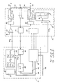
- FIG 2 illustrates a line circuit 10 and a control circuit 11 which controls the line circuit. Only those parts of the two circuits 10 and 11 which are relevant for the supply of current to the subscriber line to which the line circuit belongs are shown in the Figure. Thus, no speech paths, signalling means, etc. are shown in the Figure.
- the subscriber line inlcudes, conventionally, an A-wire and a B-wire, which are referenced 12 and 13 respectively. Seated between the wires 12, 13 is a series combination consisting of a resistor 14, a capacitor 15 and a resistor 16.
- the supply of current to the subscriber line 12, 13 is controlled in the following manner: The voltage between the A and B wires is low-pass filtered in the R-C-R link formed by the resistors 14, 16 and the capacitor 15.
- the resultant d.c. voltage is detected by an amplifier 17.
- the level of the output signal from the amplifier 17 is shifted and scaled in a signal processing circuit 18 from a normal level of 20-50 V to a level of about 0.5-1.25 V, in order to enable the signal to pass the control circuit 11. Further filtration is carried out in a low-pass filter 19, for the purpose of eliminating the alternating voltage generated by speech signals on the line and superimposed on a d.c. voltage.
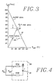
- the line circuit illustrated in Figure 2 includes a current control circuit 20 in which a plurality of different current supply characteristics are stored, among them characteristics which correspond to conventional line supply above 2 x 250 ohm, and the characteristic which corresponds to reduced supply, for instance corresponding to 2 x 10 k ⁇ in accordance with the invention. The progress followed by these two characteristics is shown in Figure 3.
- the subscriber line 12, 13 is normally supplied with 50 V across a supply resistance of 2 x 250 ohm.
- the maximum current will then be 100 milliampere and the line voltage will be 50 V, in the case of a line of indefinite length.
- This current supply characteristic is referenced with the line 21. It is proposed in accordance with the invention that the state of supplying the subscriber line with reduced line current, RP-state, shall have the characteristic corresponded by the broken line 22 in Figure 3.
- This characteristic 22 follows the characteristic 21 until the line current reaches to about 25 milliampere, whereafter the characteristic is interrupted and follows a substantially horizontal part which, in accordance with the invention, corresponds to supplying the line with 2 x 10 k ⁇ .
- signals delivered to the control circuit 11 are transmitted over a bus line 30.
- the current control circuit 20 receives an order as to which characteristic shall be selected, from a selection signal transmitted on the bus line 30, this selection signal being obtained from the main control unit.
- the current control circuit 20 delivers current to an amplifier 24, on the basis of the selected characteristic and on the basis of the measured line voltage.
- the output signal of the amplifier 24 is sent to two control circuits 25, 26 each of which controls a respective current amplifier 27, 28 which sends the line current I L determined by said characteristic to the two wires 12, 13 of the subscriber line.
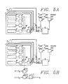
- the method of generating the desired line current I L can be described in the simplified manner illustrated in Figure 4.
- the line circuit 10 and its control circuit 11 function to produce electronically an electric circuit of the kind illustrated in Figure 4.
- This circuit includes a battery 31 with an earthed positive terminal.
- the subscriber line represented by a load resistor R L , is supplied from the battery through a respective supply resistance 32A and 32B.
- the battery voltage and the supply resistances are generated electronically.
- the EMF of the battery 31 and the supply resistances 32A and 32B are selected in accordance with selected current supply characteristics, so that the line supply current I L will equal f(V′ AB ), where V′ AB corresponds to the voltage that prevails between the A and B wires of the subscriber line subsequent to scaling in the signal processing circuit 18.
- the values of k i and I oi can be taken from a table, for instance.
- k i can be realized by applying V′ AB on a resistor chosen from several resistors of which each resistor corresponds to a respective k i -value.
- I io is generated in a corresponding manner, by applying a constant reference voltage to a resistor selected from several resistors, each corresponding to a respective I io .
- I con K i V′ AB + I io .
- the current I CON is then supplied to the amplifier 24 and the control circuits 25, 26, these circuits and the current amplifiers being of the kind described in our aforesaid WO-patent specifications.
- the operation parameters which shall be monitored in the telephone exchange module will now be described.
- the parameters are monitored and compared with reference values.
- the RP-state is activated.
- the operation parameters are monitored continuously during this RP-state period and when they finally drop below the reference values, possibly beneath modified reference values, switching of the module to normal operation is initiated.
- Figure 5a illustrates an embodiment according to which the ambient temperature T AMB of the line board 2 in the magazine 1 is monitored.
- the supply of current to the magazine from the power network is also monitored, in order to indicate the occurrence of a possible power failure.
- each line board 2 includes a local processor 47 which monitors all line circuits, normally eight in number, on the line board and which searches the line circuits on the board and reports the status of the line circuits to the main control unit 3, via a bus line 48.
- the ambient temperature is sensed by a temperature sensor in the form of an oscillator 40, shown in Figure 6, which is mounted on one of the boards in the magazine and which is connected to the bus line 48 through the intermediary of an interface 41.
- the oscillator circuit is conventional and includes a number of components which determine oscillator frequency. According to the invention, these components include a temperature responsive element 42, for instance a thermistor.
- the temperature responsive element 42 is mounted in the room in which the magazine 1 is enclosed and projects out from the magazine 1, as illustrated schematically in Figure 1. When the telephone exchange module operates normally, the oscillator produces an oscillation signal having the frequency f .
- a representation of the oscillator signal is transmitted, via bus lines 30, 48, to the main control unit 3, which includes a processor, schematically illustrated within the broken-line rectangle 3 in Figure 6, via an I/O-unit 43., to which the bus line 48 extends.
- the processor 3 includes another I/O-unit 44 which is connected with a communication bus line 45. This latter communication bus line is connected with a central processor unit CPU (not shown) which is common to several telephone exchange modules.
- a block 46 included in the main control unit 3 represents a program which compares monitored operation parameters with the reference values of the operation parameters and which initiates the generation of a first control signal for switching to the RP-state, and a second control signal for switching to a normal operation state.
- the main control unit 3 also includes a plurality of storage regions in which the reference values of the operation parameters are stored. More specifically, the control unit includes a memory region 50 in which a first frequency value of the oscillator frequency is stored. This first reference value corresponds to the circumstance when the ambient temperature T AMB is higher than a predetermined temperature T+ AMB , e.g. 40°C, and indicates that the RP-state shall be activated.
- the unit also includes a memory region 51 in which a second oscillator frequency reference value is stored. This second reference value corresponds to the circumstance when the ambient temperature T AMB has a value T ⁇ AMB suitable for normal operation, e.g. 37°C, and when the second control signal shall be produced and that the RP-state shall therefore be deactivated and a switch made to normal supply.
- T+ AMB > T ⁇ AMB a temperature hysteresis is obtained.
- the prevailing value of the oscillator frequency i.e. the prevailing temperature value T AMB is stored in a memory region 52, which is updated periodically.
- the temperature transducer, or temperature responsive element 42 may be placed centrally in the room in which all modules 1 are arranged.
- the arrangement will preferably include an additional temperature responsive element, in order to make the arrangement more reliable.
- the prevailing status of the power network i.e. whether or not there is a power failure, is indicated by means of a status signal which is sent from the central processor unit CPU (not shown) of the exchange on the communication bus line 45.
- This status signal is stored in a memory region 53.
- the program block 46 delivers the second control signal, whereas if the status signal corresponds to a power failure, the program block 46 delivers the first control signal for activating the RP-state, wherewith all subscriber lines in the module are switched to the RP-state.
- each line circuit 10 receives the signals on the bus line 30, via a control logic block 33 having three parellel data outputs on which data signals D0, D1 and D2 are sent to a control circuit 29 for adjusting the line circuit 10 to different operational modes.
- the control logic block 33 is connected to the current control circuit 20 and to a loop detector circuit 37, via a bus line 60.
- the control logic block is also connected to the A/D-converter 38, via bus 39.
- Figure 5b illustrates a variant of the monitoring system illustrated in Figure 5a.
- N o a threshhold value
- N o 4
- T AMB the ambient temperature
- T+ AMB the predetermined first reference value
- the threshhold value N o i.e. the number of active lines on each board, is stored in a memory region 64 (see Figure 6) and is compared with the number of active lines N on each board, which is reported continuously by each local processor 47 to the main control unit 3.
- the prevailing value N of the number of active line circuits on a line board is stored in a memory region 65. This storage procedure is carried out continuously with prevailing values from line board to line board, and the program block 46 calculates whether or not the threshhold value N o has been exceeded, with each prevailing value.
- An active line circuit is monitored by the loop detector 37, which detects when the line is supplied with line current.
- the state of the loop detector is monitored by the local processor 47 which controls the logic block 33 and the bus line 30, via the bus line 60. When the loop detector 37 detects line current, a report to this effect is sent to the main control unit 3.
- Figure 5c illustrates another suitable combination of operation parameters to be monitored.
- both the ambient temperature T AMB and the subscriber line length L are sensed, in addition to the possible occurrence of a power failure.
- the manner in which the length of a subscriber line influences the line current will be evident from Figure 3.
- a reference value L o of the length of the subscriber line is stored in a memory region 54 (see Figure 6) and the prevailing line length value L for each subscriber line belonging to the line boards in the magazine 1 are stored in a memory region 55 in the main control unit 3.
- the ohm-unit is normally used as a measurement of the length of a subscriber line.
- the line length L is determined by detecting the line voltage V′ AB with the aid of the amplifier 17.
- the voltage is signal-processed in the signal processing circuit 18 and low-pass filtered in the low-pass filter 19, and passes to the A/D-converter 38 on whose output the voltage value is produced in digital form and is transmitted to the control logic block 33, via a bus line 39.
- the signal is sent from the block 33 to the local processor 47, via the bus line 30, and from the local processor 47 to the main control unit 3, via the bus line 48.
- the control unit 3 delivers the first control signal over the bus line 48 only to those lines which are shorter than the reference value.
- the RP-state is activated solely for these lines. This may now be sufficient for the temperature to fall beneath the second temperature reference value T ⁇ AMB.
- the length of a call is monitored by the loop detector circuit 37, illustrated in Figure 2, which senses continuously whether or not line current is supplied to the subscriber line 12, 13.
- the line current is supplied during an ongoing call.
- the supply of line current is terminated when the subscriber replaces the receiver, optionally after a time delay, which is reported to the control logic block 33 by the loop detector circuit 37, via the bus line 60.
- the control logic block 33 sends this signal to the bus lines 30, 48 connected to the main control unit 3, which measures the duration t of this signal.
- the value of the duration of this signal is stored in a memory region 62 and is updated continuously.
- the call length reference value t o is stored in a memory region 63.
- the main control unit 3 When the call length, or call duration, exceeds the reference value, the main control unit 3 sends the first control signal to the line circuits on which the call is made and orders a transition to the RP-state. None of the other short subscriber lines is switched to the RP-state.
- Figure 5d illustrates still another operation parameter which is capable of detection and which can suitably be made the basis for switching to the RP-state.
- the temperature T j of the warmest component or the warmest circuit in each line interface circuit is detected or sensed, in addition to the status of the power network.
- the line circuit is normally an integrated circuit in the form of a capsule made, for instance, of plastic material, from which a number of legs extend.
- a temperature sensor 57 (see Figure 2) is arranged adjacent the circuit, for the purpose of measuring circuit temperature. Alternatively, the temperature sensor may be integrated in the integrated circuit and may receive its supply voltage from the line circuit.
- the temperature sensor 57 includes a temperature responsive transistor circuit which changes its output voltage V OUT when the circuit temperature T j exceeds a first temperature reference value T+ j stored in a memory region 59 in the main control unit 3.
- the temperature value T j is stored in another memory region 56 and is continuously updated.
- the main control unit 3 produces the first signal and the individual line circuit is switched to the RP-state. The reason why only the individual line circuit is affected by signals on the bus line 30 is because it is only this individual line circuit which is addressed.
- the main control unit sends the second control signal to the individual line circuit.
- Temperature sensing, or detection thus takes place individually for each line circuit and therewith affords a more accurate temperature facility than that afforded by the Figure 5a embodiment, since temperature is monitored at precisely the location where the greatest risk of overheating prevails.
- the temperature sensor 57 can be arranged for measuring the temperature at that leg of the capsule where it is known that the largest current passes. Normally, the maximum circuit temperature is about 110°C and the maximum leg temperature 85°C.
- the temperature sensor 57 is biased with the aid of a resistor in some suitable manner, so that the sensor output signal will be, for instance, +5 V when the maximum temperature for the line circuit is reached and so that this signal is 0 V when the temperature of the circuit returns to a normal operating temperature.
- the condition can be included that when T AMB > T+ AMB , the RE-state is not initiated in all line circuits on the line board when the threshhold value N o is exceeded, but only in those line circuits (among those which are found on a line board where N o has been exceeded) which have a line length L which is shorter than the line length reference value L o .
- Still another modification is one in which the RP-state is intiated solely in those line circuits (among those found on a line board where N o has been exceeded) where a call has continued over a time t which is greater than the call length reference value t o for the call length.
Landscapes
- Engineering & Computer Science (AREA)
- Signal Processing (AREA)
- Devices For Supply Of Signal Current (AREA)
- Interface Circuits In Exchanges (AREA)
- Heat-Pump Type And Storage Water Heaters (AREA)
- Generation Of Surge Voltage And Current (AREA)
- Valve Device For Special Equipments (AREA)
Applications Claiming Priority (2)
| Application Number | Priority Date | Filing Date | Title |
|---|---|---|---|
| SE9000929A SE465799B (sv) | 1990-03-15 | 1990-03-15 | Anordning foer reducerad effektmatning till en abonnentlinje |
| SE9000929 | 1990-03-15 |
Publications (2)
| Publication Number | Publication Date |
|---|---|
| EP0452286A1 true EP0452286A1 (de) | 1991-10-16 |
| EP0452286B1 EP0452286B1 (de) | 1995-09-13 |
Family
ID=20378873
Family Applications (1)
| Application Number | Title | Priority Date | Filing Date |
|---|---|---|---|
| EP91850030A Expired - Lifetime EP0452286B1 (de) | 1990-03-15 | 1991-02-11 | Vorrichtung zur Speisung einer Teilnehmerleitung mit reduzierter Leistung |
Country Status (18)
| Country | Link |
|---|---|
| US (1) | US5323453A (de) |
| EP (1) | EP0452286B1 (de) |
| JP (1) | JPH05505708A (de) |
| KR (1) | KR0129037B1 (de) |
| AU (1) | AU650263B2 (de) |
| BR (1) | BR9106161A (de) |
| CA (1) | CA2074479A1 (de) |
| DE (1) | DE69112887T2 (de) |
| DK (1) | DK0452286T3 (de) |
| ES (1) | ES2077836T3 (de) |
| FI (1) | FI923862L (de) |
| GR (1) | GR3017667T3 (de) |
| IE (1) | IE69576B1 (de) |
| NO (1) | NO923433D0 (de) |
| PT (1) | PT97039B (de) |
| SE (1) | SE465799B (de) |
| TN (1) | TNSN91014A1 (de) |
| WO (1) | WO1991014333A1 (de) |
Cited By (2)
| Publication number | Priority date | Publication date | Assignee | Title |
|---|---|---|---|---|
| WO1998028904A3 (de) * | 1996-12-20 | 1998-08-13 | Siemens Ag | Verfahren und anordnung zur fernspeisung mehrerer gleichartiger verbraucher aus einer energiequelle |
| WO2000039994A1 (en) * | 1998-12-30 | 2000-07-06 | Alcatel Usa Sourcing, L.P. | System and method of power limiting call processing in telecommunications equipment |
Families Citing this family (6)
| Publication number | Priority date | Publication date | Assignee | Title |
|---|---|---|---|---|
| WO1995001692A1 (en) * | 1993-06-30 | 1995-01-12 | Motorola Inc. | Electronic device having internal charge regulator |
| JP3360184B2 (ja) * | 1993-09-20 | 2002-12-24 | 富士通株式会社 | 光加入者伝送システムに於ける給電制御方式 |
| SE507739C2 (sv) * | 1996-11-08 | 1998-07-06 | Ericsson Telefon Ab L M | Anordning vid en linjekrets för mätning av linjespänning |
| JPH10243093A (ja) * | 1996-12-25 | 1998-09-11 | Fujitsu Ltd | 無給電通信方法及び交換機 |
| US7480713B2 (en) * | 2000-12-15 | 2009-01-20 | International Business Machines Corporation | Method and system for network management with redundant monitoring and categorization of endpoints |
| WO2008038617A1 (en) * | 2006-09-29 | 2008-04-03 | Nec Corporation | Signal selecting apparatus, circuit amending apparatus, circuit simulator, circuit emulator, method of signal selection and program |
Citations (2)
| Publication number | Priority date | Publication date | Assignee | Title |
|---|---|---|---|---|
| US4254305A (en) * | 1979-02-07 | 1981-03-03 | International Telephone And Telegraph Corporation | Current limited subscriber line feed circuit |
| GB2064915A (en) * | 1979-11-29 | 1981-06-17 | Standard Telephones Cables Ltd | Telephone line feed circuit |
Family Cites Families (13)
| Publication number | Priority date | Publication date | Assignee | Title |
|---|---|---|---|---|
| CH586983A5 (de) * | 1974-12-23 | 1977-04-15 | Ibm | |
| GB2071461B (en) * | 1980-02-14 | 1984-01-25 | Standard Telephones Cables Ltd | Telephone line feed |
| JPS5737967A (en) * | 1980-08-15 | 1982-03-02 | Nec Corp | Talking current supply protecting circuit |
| CA1157175A (en) * | 1981-02-20 | 1983-11-15 | Mitel Corporation | Power saving line circuit |
| SE431704B (sv) * | 1982-07-06 | 1984-02-20 | Ericsson Telefon Ab L M | Forfarande vid strommatning av en abonnentapparat fran en telefonvexel |
| SE433284B (sv) * | 1982-09-17 | 1984-05-14 | Ericsson Telefon Ab L M | Anordning for strommatning av en abonnentapparat |
| SE433285B (sv) * | 1982-09-22 | 1984-05-14 | Ericsson Telefon Ab L M | Anordning for strommatning av en abonnentapparat |
| JPS5981960A (ja) * | 1982-11-01 | 1984-05-11 | Nippon Telegr & Teleph Corp <Ntt> | 可変給電特性型電流供給回路 |
| DE3431074A1 (de) * | 1984-08-23 | 1986-02-27 | Siemens AG, 1000 Berlin und 8000 München | Schaltungsanordnung fuer eine kleine fernsprechnebenstellenanlage |
| US4653088A (en) * | 1985-03-25 | 1987-03-24 | Wang Laboratories, Inc. | Telephone circuitry with power backup |
| US4760379A (en) * | 1986-09-05 | 1988-07-26 | Bell Of Pennsylvania | Fail-safe high temperature alarm |
| JPS6457866A (en) * | 1987-08-28 | 1989-03-06 | Fujitsu Ltd | Feeding current control circuit |
| US4856059A (en) * | 1987-11-13 | 1989-08-08 | Itec, Inc. | Semiconductor subscriber line interface circuit with enhanced survivability |
-
1990
- 1990-03-15 SE SE9000929A patent/SE465799B/sv not_active IP Right Cessation
-
1991
- 1991-02-11 CA CA002074479A patent/CA2074479A1/en not_active Abandoned
- 1991-02-11 AU AU75410/91A patent/AU650263B2/en not_active Ceased
- 1991-02-11 FI FI923862A patent/FI923862L/fi unknown
- 1991-02-11 JP JP91506375A patent/JPH05505708A/ja active Pending
- 1991-02-11 DK DK91850030.7T patent/DK0452286T3/da active
- 1991-02-11 WO PCT/SE1991/000092 patent/WO1991014333A1/en not_active Ceased
- 1991-02-11 ES ES91850030T patent/ES2077836T3/es not_active Expired - Lifetime
- 1991-02-11 BR BR919106161A patent/BR9106161A/pt not_active IP Right Cessation
- 1991-02-11 KR KR1019920702201A patent/KR0129037B1/ko not_active Expired - Fee Related
- 1991-02-11 DE DE69112887T patent/DE69112887T2/de not_active Expired - Fee Related
- 1991-02-11 EP EP91850030A patent/EP0452286B1/de not_active Expired - Lifetime
- 1991-03-12 IE IE81591A patent/IE69576B1/en not_active IP Right Cessation
- 1991-03-14 US US07/669,615 patent/US5323453A/en not_active Expired - Lifetime
- 1991-03-14 PT PT97039A patent/PT97039B/pt not_active IP Right Cessation
- 1991-03-15 TN TNTNSN91014A patent/TNSN91014A1/fr unknown
-
1992
- 1992-09-03 NO NO923433A patent/NO923433D0/no unknown
-
1995
- 1995-10-06 GR GR950402771T patent/GR3017667T3/el unknown
Patent Citations (2)
| Publication number | Priority date | Publication date | Assignee | Title |
|---|---|---|---|---|
| US4254305A (en) * | 1979-02-07 | 1981-03-03 | International Telephone And Telegraph Corporation | Current limited subscriber line feed circuit |
| GB2064915A (en) * | 1979-11-29 | 1981-06-17 | Standard Telephones Cables Ltd | Telephone line feed circuit |
Non-Patent Citations (2)
| Title |
|---|
| PATENT ABSTRACTS OF JAPAN, Vol. 6, No. 107 (L-113); & JP-A-57 037 967 (Nippon Denki K.K. et al.) 02-03-1982 * |
| PATENT ABSTRACTS OF JAPAN, Vol. 8, No. 194 (E-264); & JP-A-59 081 960 (Nippon Denshin Denwa Kosha et al.) 11-05-1984 * |
Cited By (3)
| Publication number | Priority date | Publication date | Assignee | Title |
|---|---|---|---|---|
| WO1998028904A3 (de) * | 1996-12-20 | 1998-08-13 | Siemens Ag | Verfahren und anordnung zur fernspeisung mehrerer gleichartiger verbraucher aus einer energiequelle |
| WO2000039994A1 (en) * | 1998-12-30 | 2000-07-06 | Alcatel Usa Sourcing, L.P. | System and method of power limiting call processing in telecommunications equipment |
| US6278778B1 (en) | 1998-12-30 | 2001-08-21 | Alcatel Usa Sourcing, L.P. | System and method of power limiting call processing in telecommunications equipment |
Also Published As
| Publication number | Publication date |
|---|---|
| US5323453A (en) | 1994-06-21 |
| AU7541091A (en) | 1991-10-10 |
| BR9106161A (pt) | 1993-03-16 |
| FI923862A0 (fi) | 1992-08-28 |
| KR930701044A (ko) | 1993-03-16 |
| NO923433L (no) | 1992-09-03 |
| JPH05505708A (ja) | 1993-08-19 |
| DK0452286T3 (da) | 1995-11-13 |
| PT97039B (pt) | 1998-10-30 |
| GR3017667T3 (en) | 1996-01-31 |
| IE69576B1 (en) | 1996-10-02 |
| DE69112887T2 (de) | 1996-03-14 |
| NO923433D0 (no) | 1992-09-03 |
| FI923862A7 (fi) | 1992-08-28 |
| FI923862L (fi) | 1992-08-28 |
| IE910815A1 (en) | 1991-09-25 |
| ES2077836T3 (es) | 1995-12-01 |
| WO1991014333A1 (en) | 1991-09-19 |
| SE9000929L (sv) | 1991-09-16 |
| SE9000929D0 (sv) | 1990-03-15 |
| KR0129037B1 (ko) | 1998-04-08 |
| TNSN91014A1 (fr) | 1992-10-25 |
| AU650263B2 (en) | 1994-06-16 |
| EP0452286B1 (de) | 1995-09-13 |
| PT97039A (pt) | 1993-03-31 |
| SE465799B (sv) | 1991-10-28 |
| DE69112887D1 (de) | 1995-10-19 |
| CA2074479A1 (en) | 1991-09-16 |
Similar Documents
| Publication | Publication Date | Title |
|---|---|---|
| EP0115675B1 (de) | Gerät zur Sendung von Informationen über Fernsprechleitungen | |
| US5323453A (en) | Power down feed | |
| US4639553A (en) | Call signal detecting device | |
| US5265154A (en) | Telephone controller apparatus | |
| JP4044962B2 (ja) | 電話回線モニタ回路 | |
| EP0347937A2 (de) | Funk-Telekommunikationsgerät, fähig zur Verminderung der Verlustleistung | |
| US5241591A (en) | Telephone system having a dial data changeover switch | |
| US4528427A (en) | Test system and device for locating short circuits and open circuits in a two-lead line | |
| US20040125749A1 (en) | Communication apparatus | |
| EP0497679B1 (de) | Übertragungsgerät | |
| JPH0740703B2 (ja) | 通信装置 | |
| EP0366991A2 (de) | Verfahren und Vorrichtung um die aufgenommene Leistung einer Telefonschnittstellenschaltung im Ruhe-Zustand gering zu halten | |
| KR100296833B1 (ko) | 자동손실제어회로 | |
| JP3321255B2 (ja) | 網制御装置 | |
| JP3728910B2 (ja) | 電話装置 | |
| USRE35582E (en) | Subscriber line interface circuit with power-down mode | |
| JP3332663B2 (ja) | ファクシミリ装置 | |
| JP3458459B2 (ja) | 回線端末装置 | |
| EP0703693B1 (de) | Vorrichtung für Telefoneigenecho | |
| JPH11127235A (ja) | 回線端末装置 | |
| JPH04119095A (ja) | 加入者線インタフエース装置 | |
| JPS6022858A (ja) | 指令電話システムにおける制御信号調整方式 | |
| JPH0793673B2 (ja) | 画像通信装置 | |
| WO2001004860A1 (en) | Remote operational status notification system for electronic animal control apparatus | |
| JPH0732423B2 (ja) | 呼出応答検出方式 |
Legal Events
| Date | Code | Title | Description |
|---|---|---|---|
| PUAI | Public reference made under article 153(3) epc to a published international application that has entered the european phase |
Free format text: ORIGINAL CODE: 0009012 |
|
| AK | Designated contracting states |
Kind code of ref document: A1 Designated state(s): BE CH DE DK ES FR GB GR IT LI NL |
|
| 17P | Request for examination filed |
Effective date: 19920228 |
|
| 17Q | First examination report despatched |
Effective date: 19940314 |
|
| GRAA | (expected) grant |
Free format text: ORIGINAL CODE: 0009210 |
|
| AK | Designated contracting states |
Kind code of ref document: B1 Designated state(s): BE CH DE DK ES FR GB GR IT LI NL |
|
| ITF | It: translation for a ep patent filed | ||
| REF | Corresponds to: |
Ref document number: 69112887 Country of ref document: DE Date of ref document: 19951019 |
|
| ET | Fr: translation filed | ||
| REG | Reference to a national code |
Ref country code: DK Ref legal event code: T3 |
|
| REG | Reference to a national code |
Ref country code: ES Ref legal event code: FG2A Ref document number: 2077836 Country of ref document: ES Kind code of ref document: T3 |
|
| REG | Reference to a national code |
Ref country code: GR Ref legal event code: FG4A Free format text: 3017667 |
|
| PLBE | No opposition filed within time limit |
Free format text: ORIGINAL CODE: 0009261 |
|
| STAA | Information on the status of an ep patent application or granted ep patent |
Free format text: STATUS: NO OPPOSITION FILED WITHIN TIME LIMIT |
|
| 26N | No opposition filed | ||
| PGFP | Annual fee paid to national office [announced via postgrant information from national office to epo] |
Ref country code: GR Payment date: 19980130 Year of fee payment: 8 Ref country code: BE Payment date: 19980130 Year of fee payment: 8 |
|
| PGFP | Annual fee paid to national office [announced via postgrant information from national office to epo] |
Ref country code: DK Payment date: 19980204 Year of fee payment: 8 |
|
| PGFP | Annual fee paid to national office [announced via postgrant information from national office to epo] |
Ref country code: NL Payment date: 19980228 Year of fee payment: 8 |
|
| PGFP | Annual fee paid to national office [announced via postgrant information from national office to epo] |
Ref country code: CH Payment date: 19980304 Year of fee payment: 8 |
|
| PG25 | Lapsed in a contracting state [announced via postgrant information from national office to epo] |
Ref country code: LI Free format text: LAPSE BECAUSE OF NON-PAYMENT OF DUE FEES Effective date: 19990228 Ref country code: GR Free format text: LAPSE BECAUSE OF NON-PAYMENT OF DUE FEES Effective date: 19990228 Ref country code: CH Free format text: LAPSE BECAUSE OF NON-PAYMENT OF DUE FEES Effective date: 19990228 Ref country code: BE Free format text: LAPSE BECAUSE OF NON-PAYMENT OF DUE FEES Effective date: 19990228 |
|
| PG25 | Lapsed in a contracting state [announced via postgrant information from national office to epo] |
Ref country code: DK Free format text: LAPSE BECAUSE OF NON-PAYMENT OF DUE FEES Effective date: 19990301 |
|
| BERE | Be: lapsed |
Owner name: TELEFONAKTIEBOLAGET L M ERICSSON Effective date: 19990228 |
|
| PG25 | Lapsed in a contracting state [announced via postgrant information from national office to epo] |
Ref country code: NL Free format text: LAPSE BECAUSE OF NON-PAYMENT OF DUE FEES Effective date: 19990901 |
|
| REG | Reference to a national code |
Ref country code: CH Ref legal event code: PL |
|
| REG | Reference to a national code |
Ref country code: DK Ref legal event code: EBP |
|
| PGFP | Annual fee paid to national office [announced via postgrant information from national office to epo] |
Ref country code: DE Payment date: 20010118 Year of fee payment: 11 |
|
| REG | Reference to a national code |
Ref country code: GB Ref legal event code: IF02 |
|
| PGFP | Annual fee paid to national office [announced via postgrant information from national office to epo] |
Ref country code: FR Payment date: 20020117 Year of fee payment: 12 |
|
| PGFP | Annual fee paid to national office [announced via postgrant information from national office to epo] |
Ref country code: GB Payment date: 20020121 Year of fee payment: 12 |
|
| PGFP | Annual fee paid to national office [announced via postgrant information from national office to epo] |
Ref country code: ES Payment date: 20020311 Year of fee payment: 12 |
|
| PG25 | Lapsed in a contracting state [announced via postgrant information from national office to epo] |
Ref country code: DE Free format text: LAPSE BECAUSE OF NON-PAYMENT OF DUE FEES Effective date: 20020903 |
|
| PG25 | Lapsed in a contracting state [announced via postgrant information from national office to epo] |
Ref country code: GB Free format text: LAPSE BECAUSE OF NON-PAYMENT OF DUE FEES Effective date: 20030211 |
|
| PG25 | Lapsed in a contracting state [announced via postgrant information from national office to epo] |
Ref country code: ES Free format text: LAPSE BECAUSE OF NON-PAYMENT OF DUE FEES Effective date: 20030212 |
|
| GBPC | Gb: european patent ceased through non-payment of renewal fee | ||
| PG25 | Lapsed in a contracting state [announced via postgrant information from national office to epo] |
Ref country code: FR Free format text: LAPSE BECAUSE OF NON-PAYMENT OF DUE FEES Effective date: 20031031 |
|
| REG | Reference to a national code |
Ref country code: FR Ref legal event code: ST |
|
| REG | Reference to a national code |
Ref country code: ES Ref legal event code: FD2A Effective date: 20030212 |
|
| PG25 | Lapsed in a contracting state [announced via postgrant information from national office to epo] |
Ref country code: IT Free format text: LAPSE BECAUSE OF NON-PAYMENT OF DUE FEES Effective date: 20050211 |