EP0452714A1 - Dispositif de verrouillage pour appareils de commutation électromagnétiques - Google Patents
Dispositif de verrouillage pour appareils de commutation électromagnétiques Download PDFInfo
- Publication number
- EP0452714A1 EP0452714A1 EP19910104818 EP91104818A EP0452714A1 EP 0452714 A1 EP0452714 A1 EP 0452714A1 EP 19910104818 EP19910104818 EP 19910104818 EP 91104818 A EP91104818 A EP 91104818A EP 0452714 A1 EP0452714 A1 EP 0452714A1
- Authority
- EP
- European Patent Office
- Prior art keywords
- locking device
- switching devices
- locking
- parts
- electromagnetic switching
- Prior art date
- Legal status (The legal status is an assumption and is not a legal conclusion. Google has not performed a legal analysis and makes no representation as to the accuracy of the status listed.)
- Granted
Links
Images

Classifications
-
- H—ELECTRICITY
- H01—ELECTRIC ELEMENTS
- H01H—ELECTRIC SWITCHES; RELAYS; SELECTORS; EMERGENCY PROTECTIVE DEVICES
- H01H50/00—Details of electromagnetic relays
- H01H50/16—Magnetic circuit arrangements
- H01H50/18—Movable parts of magnetic circuits, e.g. armature
- H01H50/32—Latching movable parts mechanically
- H01H50/323—Latching movable parts mechanically for interlocking two or more relays
-
- H—ELECTRICITY
- H01—ELECTRIC ELEMENTS
- H01H—ELECTRIC SWITCHES; RELAYS; SELECTORS; EMERGENCY PROTECTIVE DEVICES
- H01H50/00—Details of electromagnetic relays
- H01H50/54—Contact arrangements
- H01H50/541—Auxiliary contact devices
- H01H50/545—Self-contained, easily replaceable microswitches
Definitions
- the invention relates to a locking device for mechanically switching off one of two electromagnetic switching devices arranged next to one another, as long as the other switching device is in its switched-on position, the movable parts of the switching devices being able to be coupled to locking members extending from the locking device.
- the locking device is provided with a heart-like, axleless rocker in a housing.
- the locking members are designed here as pin-like parts that extend perpendicular to the plane of movement of the rocker and diametrically from each other in the direction of their respective switching devices to be attached. These pin-like parts are guided in a circular arc shape in the recesses provided in the provided rocker movements.
- the ends of the pin-shaped parts protruding from the housing are inserted through the side walls of the switchgear into grooves of driver links.
- the housing of the locking device is connected here by means of snap hooks which snap into correspondingly adapted recesses in the switching devices and held on the switching devices.
- the invention has for its object to improve a locking device of the type mentioned above so that coupling to electromagnetic switching devices is possible without special constructive, specific training of the switching devices.
- This is achieved in a simple manner in that the movable parts of the switching devices are the coupling parts for auxiliary switches that can be placed on the switching device and the blocking elements of these coupling parts are adjusted. It has proven to be advantageous if the coupling parts are designed like hammer heads and the locking members are slides, the free ends of which run around the hammer head.
- the other ends of the slide are positively coupled to a locking rocker, the tip of which is supported on a locking contour in the housing of the locking device in the event of a lock.
- the housing of the locking device is provided with the molded parts adapted to the mounting of the auxiliary switches. It is advantageous here if the locking members are attached in the grid of the coupling parts with a certain surcharge.
- the locking device is applied to the moving parts of the switching devices transversely to the direction of movement can be pushed on and coupled and that at least one slide is provided for releasably latching the locking device on the switching devices.
- a common slide for coupling with fixed parts of the switching devices can advantageously be present here.
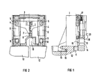
- the locking device consists of the housing 1, in which a rocker 3, which is spring-loaded via a spring 2, is spring-loaded against the movement switching direction of locking members 4.
- the locking members 4 are more or less positively coupled via pins 5 formed on the rocker 3, which protrude into recesses 6 of the locking members 4.
- the locking members 4 are slidably guided in the housing 1 as a locking slide.
- the rocker is triangular in shape and slides past one of the locking slides with the triangular tip 7 at a short distance from correspondingly shaped surfaces 8 of the housing 1, so that the downward movement of the other locking slide 4 is prevented. This device cannot turn on.
- the locking slide 4 are further equipped with rectangular openings 9 which are open to the free side, so that a hammer head 10 can be largely inserted in a form-fitting manner, which is integrally formed on the contact bridge support 11 of an electromagnetic switching device 12. Coupling arrangements of this type have become known, for example, from DE-GM 88 05 878.
- the hammer head 10 is adapted to a hammer head-shaped projection 13 on the housing of the electromagnetic switching device 12, which cooperate with corresponding projections 14 on the housing 1 of the locking device.
- Two hook-shaped lugs 15 on the housing 1 of the locking device engage when the locking device is moved into the operating position in a correspondingly shaped recess 16, so that the housing 1 is firmly connected to the housing of the electromagnetic switching device 12 at three points.
- a slide 20 is provided for releasable locking.
- the slide 20 is displaceable against the force of a spring 17 or resilient plastic tongues to release the hammer head-shaped formation.
- An inclined surface 18 pushes the slide 20 back against the force of the spring when the locking device is placed on it, until it locks behind the hammer head-shaped projection 13.
- the molded shape 19 provided in the housing 1 is arranged in the grid dimension for the spacing of the individual auxiliary switch locations, as can be seen from FIGS. 3-6.
- FIG. 3 it is possible to place two auxiliary switch blocks in the left contactor and three auxiliary switch blocks in the right contactor, both electromagnetic switching devices 12 being quite close to one another apart from a short distance.
- three auxiliary switch blocks are to be applied to both contactors, this can be done according to FIG. 4 in that both electromagnetic switching devices 12 are attached to the standard mounting rail at a certain distance from one another.
- the same situation applies to a somewhat larger series of electromagnetic switching devices, as shown in FIG. 5.
- the locking device can be used with shooters 12 who belong to a larger series.
- the individual auxiliary switch blocks are located further away from the edge of the switching devices, so that it is always possible to place three auxiliary switch blocks on both electromagnetic switching devices.
Landscapes
- Physics & Mathematics (AREA)
- Electromagnetism (AREA)
- Switch Cases, Indication, And Locking (AREA)
- Push-Button Switches (AREA)
Applications Claiming Priority (2)
| Application Number | Priority Date | Filing Date | Title |
|---|---|---|---|
| DE9004431U DE9004431U1 (de) | 1990-04-18 | 1990-04-18 | Verriegelungsvorrichtung für elektromagnetische Schaltgeräte |
| DE9004431U | 1990-04-18 |
Publications (2)
| Publication Number | Publication Date |
|---|---|
| EP0452714A1 true EP0452714A1 (fr) | 1991-10-23 |
| EP0452714B1 EP0452714B1 (fr) | 1995-10-18 |
Family
ID=6853008
Family Applications (1)
| Application Number | Title | Priority Date | Filing Date |
|---|---|---|---|
| EP91104818A Expired - Lifetime EP0452714B1 (fr) | 1990-04-18 | 1991-03-26 | Dispositif de verrouillage pour appareils de commutation électromagnétiques |
Country Status (4)
| Country | Link |
|---|---|
| US (1) | US5189385A (fr) |
| EP (1) | EP0452714B1 (fr) |
| JP (1) | JPH04230924A (fr) |
| DE (2) | DE9004431U1 (fr) |
Families Citing this family (7)
| Publication number | Priority date | Publication date | Assignee | Title |
|---|---|---|---|---|
| US5648646A (en) * | 1995-06-19 | 1997-07-15 | Reliance Time Controls, Inc. | Circuit breaker linkage assembly |
| US6184595B1 (en) | 1999-01-13 | 2001-02-06 | Reliance Controls Corporation | Interlock for transversely oriented circuit breaker switches |
| US6031193A (en) * | 1999-01-15 | 2000-02-29 | Reliance Controls Corporation | Circuit breaker switch interlock |
| US6066817A (en) * | 1999-03-16 | 2000-05-23 | Reliance Controls Corporation | Socket-type circuit breaker mounting system |
| US6096986A (en) * | 1999-09-08 | 2000-08-01 | Reliance Controls Corporation | Channel-type circuit breaker switch interlock |
| US6861596B2 (en) * | 2002-02-19 | 2005-03-01 | Gen-Tran Corporation | Switch interlock apparatus |
| FR2907963B1 (fr) * | 2006-10-27 | 2009-01-09 | Abb Entrelec Soc Par Actions S | Module de raccordement electrique entre un premier et un second contacteurs et montage inverseur correspondant |
Citations (3)
| Publication number | Priority date | Publication date | Assignee | Title |
|---|---|---|---|---|
| DE2114509A1 (de) * | 1971-03-25 | 1972-10-05 | Metzenauer & Jung Gmbh | Aus zwei Schützen aufgebaute Anordnung mit mechanischer Verriegelungseinrichtung |
| DE3011779A1 (de) * | 1980-03-27 | 1981-10-01 | Metzenauer & Jung Gmbh, 5600 Wuppertal | Mechanische verriegelungseinrichtung gegen gleichzeitiges einschalten zweier schuetze |
| DE8805878U1 (de) * | 1988-05-03 | 1989-09-07 | Siemens AG, 1000 Berlin und 8000 München | Hilfsschalteraufsatzblock |
Family Cites Families (2)
| Publication number | Priority date | Publication date | Assignee | Title |
|---|---|---|---|---|
| ES287600A1 (es) * | 1962-08-17 | 1964-01-16 | Telemecanique Electrique | Dispositivo de bloqueo mecánico recíproco de dos aparatos eléctricos |
| DE3213477A1 (de) * | 1982-04-10 | 1983-10-13 | Brown, Boveri & Cie Ag, 6800 Mannheim | Verriegelungsvorrichtung fuer elektrische schaltorgane |
-
1990
- 1990-04-18 DE DE9004431U patent/DE9004431U1/de not_active Expired - Lifetime
-
1991
- 1991-03-26 EP EP91104818A patent/EP0452714B1/fr not_active Expired - Lifetime
- 1991-03-26 DE DE59106700T patent/DE59106700D1/de not_active Expired - Fee Related
- 1991-04-16 US US07/686,046 patent/US5189385A/en not_active Expired - Fee Related
- 1991-04-17 JP JP3114071A patent/JPH04230924A/ja not_active Withdrawn
Patent Citations (3)
| Publication number | Priority date | Publication date | Assignee | Title |
|---|---|---|---|---|
| DE2114509A1 (de) * | 1971-03-25 | 1972-10-05 | Metzenauer & Jung Gmbh | Aus zwei Schützen aufgebaute Anordnung mit mechanischer Verriegelungseinrichtung |
| DE3011779A1 (de) * | 1980-03-27 | 1981-10-01 | Metzenauer & Jung Gmbh, 5600 Wuppertal | Mechanische verriegelungseinrichtung gegen gleichzeitiges einschalten zweier schuetze |
| DE8805878U1 (de) * | 1988-05-03 | 1989-09-07 | Siemens AG, 1000 Berlin und 8000 München | Hilfsschalteraufsatzblock |
Also Published As
| Publication number | Publication date |
|---|---|
| DE9004431U1 (de) | 1991-08-14 |
| US5189385A (en) | 1993-02-23 |
| EP0452714B1 (fr) | 1995-10-18 |
| JPH04230924A (ja) | 1992-08-19 |
| DE59106700D1 (de) | 1995-11-23 |
Similar Documents
| Publication | Publication Date | Title |
|---|---|---|
| DE19548480C1 (de) | Schaltgeräteeinheit | |
| DE19713978C2 (de) | Kippschaltvorrichtung | |
| DE4202214A1 (de) | Elektrischer schalter | |
| DE2026024C3 (de) | Schiebewiderstand mit Schalter | |
| DE1920784A1 (de) | Schiebeschalter fuer Geraete mit einem von einer Isolierstoffplatte getragenen Leiternetz | |
| EP0452714B1 (fr) | Dispositif de verrouillage pour appareils de commutation électromagnétiques | |
| EP1074030A1 (fr) | Appareil de commutation comportant un module a chambre de coupure | |
| DE1465705B1 (de) | Elektrischer Schnappschalter mit Drueckerhebel | |
| DE4207156C2 (de) | Konstruktion eines elektrischen Schalters und eines Sicherungshalters | |
| DE1540160B1 (de) | Elektrischer Schalter mit laengsverschiebbarer Kontaktbruecke | |
| DE3416055A1 (de) | Mechanische verriegelungsvorrichtung von zwei unmittelbar benachbarten schaltgeraeten | |
| DE1953264U (de) | Schalteinrichtung mit brueckenkontakten. | |
| EP0000711A1 (fr) | Contacteur avec bornes de raccordement librement accessibles et disposées dans des plans différents | |
| DE2541922B2 (de) | Verriegelbarer Drucktastenschalter | |
| DE3909061A1 (de) | Sperrvorrichtung gegen gleichzeitiges einschalten zweier mechanisch oder elektromagnetisch betaetigter schaltorgane | |
| DE3324253C2 (fr) | ||
| DE2547278C2 (de) | Elektrischer Schnappschalter | |
| DE2904646C2 (de) | Drucktastenschalter | |
| DE2437509C2 (de) | Sicherungstrennschalter | |
| DE69508367T2 (de) | Ausschaltanordnung mit bogenförmigen Sicherungshalter | |
| DE19709198A1 (de) | Steckeranordnung mit einem Betätigungsschieber | |
| DE2733800A1 (de) | Relais | |
| DE7320723U (de) | Fahrtrichtungs Fernlicht Abblendlicht Lichthupen Schalter | |
| DE69206389T2 (de) | Mehrpoliges Schaltgerät mit teilweise vorübergehender Betätigung. | |
| DE4226508C2 (de) | Schiebeschalter |
Legal Events
| Date | Code | Title | Description |
|---|---|---|---|
| PUAI | Public reference made under article 153(3) epc to a published international application that has entered the european phase |
Free format text: ORIGINAL CODE: 0009012 |
|
| AK | Designated contracting states |
Kind code of ref document: A1 Designated state(s): CH DE FR GB IT LI SE |
|
| 17P | Request for examination filed |
Effective date: 19920421 |
|
| RIN1 | Information on inventor provided before grant (corrected) |
Inventor name: GNAHN, GUENTHER, DIPL.-ING. |
|
| 17Q | First examination report despatched |
Effective date: 19940321 |
|
| GRAA | (expected) grant |
Free format text: ORIGINAL CODE: 0009210 |
|
| AK | Designated contracting states |
Kind code of ref document: B1 Designated state(s): CH DE FR GB IT LI SE |
|
| REG | Reference to a national code |
Ref country code: CH Ref legal event code: PFA Free format text: SIEMENS AKTIENGESELLSCHAFT BERLIN UND MUENCHEN TRANSFER- SIEMENS AKTIENGESELLSCHAFT |
|
| REF | Corresponds to: |
Ref document number: 59106700 Country of ref document: DE Date of ref document: 19951123 |
|
| GBT | Gb: translation of ep patent filed (gb section 77(6)(a)/1977) |
Effective date: 19951130 |
|
| ITF | It: translation for a ep patent filed | ||
| PGFP | Annual fee paid to national office [announced via postgrant information from national office to epo] |
Ref country code: GB Payment date: 19960220 Year of fee payment: 6 |
|
| ET | Fr: translation filed | ||
| PGFP | Annual fee paid to national office [announced via postgrant information from national office to epo] |
Ref country code: SE Payment date: 19960320 Year of fee payment: 6 |
|
| PGFP | Annual fee paid to national office [announced via postgrant information from national office to epo] |
Ref country code: CH Payment date: 19960624 Year of fee payment: 6 |
|
| PLBE | No opposition filed within time limit |
Free format text: ORIGINAL CODE: 0009261 |
|
| STAA | Information on the status of an ep patent application or granted ep patent |
Free format text: STATUS: NO OPPOSITION FILED WITHIN TIME LIMIT |
|
| 26N | No opposition filed | ||
| PG25 | Lapsed in a contracting state [announced via postgrant information from national office to epo] |
Ref country code: GB Effective date: 19970326 |
|
| PG25 | Lapsed in a contracting state [announced via postgrant information from national office to epo] |
Ref country code: SE Effective date: 19970327 |
|
| PG25 | Lapsed in a contracting state [announced via postgrant information from national office to epo] |
Ref country code: LI Effective date: 19970331 Ref country code: CH Effective date: 19970331 |
|
| REG | Reference to a national code |
Ref country code: CH Ref legal event code: PL |
|
| GBPC | Gb: european patent ceased through non-payment of renewal fee |
Effective date: 19970326 |
|
| EUG | Se: european patent has lapsed |
Ref document number: 91104818.9 |
|
| PG25 | Lapsed in a contracting state [announced via postgrant information from national office to epo] |
Ref country code: IT Free format text: LAPSE BECAUSE OF NON-PAYMENT OF DUE FEES;WARNING: LAPSES OF ITALIAN PATENTS WITH EFFECTIVE DATE BEFORE 2007 MAY HAVE OCCURRED AT ANY TIME BEFORE 2007. THE CORRECT EFFECTIVE DATE MAY BE DIFFERENT FROM THE ONE RECORDED. Effective date: 20050326 |
|
| PGFP | Annual fee paid to national office [announced via postgrant information from national office to epo] |
Ref country code: FR Payment date: 20080317 Year of fee payment: 18 Ref country code: DE Payment date: 20080519 Year of fee payment: 18 |
|
| REG | Reference to a national code |
Ref country code: FR Ref legal event code: ST Effective date: 20091130 |
|
| PG25 | Lapsed in a contracting state [announced via postgrant information from national office to epo] |
Ref country code: DE Free format text: LAPSE BECAUSE OF NON-PAYMENT OF DUE FEES Effective date: 20091001 |
|
| PG25 | Lapsed in a contracting state [announced via postgrant information from national office to epo] |
Ref country code: FR Free format text: LAPSE BECAUSE OF NON-PAYMENT OF DUE FEES Effective date: 20091123 |