EP0452887A2 - Steuerungssystem für ein Momentwandler - Google Patents
Steuerungssystem für ein Momentwandler Download PDFInfo
- Publication number
- EP0452887A2 EP0452887A2 EP91106063A EP91106063A EP0452887A2 EP 0452887 A2 EP0452887 A2 EP 0452887A2 EP 91106063 A EP91106063 A EP 91106063A EP 91106063 A EP91106063 A EP 91106063A EP 0452887 A2 EP0452887 A2 EP 0452887A2
- Authority
- EP
- European Patent Office
- Prior art keywords
- pressure
- control system
- recited
- hydraulic pressure
- control
- Prior art date
- Legal status (The legal status is an assumption and is not a legal conclusion. Google has not performed a legal analysis and makes no representation as to the accuracy of the status listed.)
- Granted
Links
Images



Classifications
-
- F—MECHANICAL ENGINEERING; LIGHTING; HEATING; WEAPONS; BLASTING
- F16—ENGINEERING ELEMENTS AND UNITS; GENERAL MEASURES FOR PRODUCING AND MAINTAINING EFFECTIVE FUNCTIONING OF MACHINES OR INSTALLATIONS; THERMAL INSULATION IN GENERAL
- F16H—GEARING
- F16H63/00—Control outputs from the control unit to change-speed- or reversing-gearings for conveying rotary motion or to other devices than the final output mechanism
-
- F—MECHANICAL ENGINEERING; LIGHTING; HEATING; WEAPONS; BLASTING
- F16—ENGINEERING ELEMENTS AND UNITS; GENERAL MEASURES FOR PRODUCING AND MAINTAINING EFFECTIVE FUNCTIONING OF MACHINES OR INSTALLATIONS; THERMAL INSULATION IN GENERAL
- F16H—GEARING
- F16H61/00—Control functions within control units of change-speed- or reversing-gearings for conveying rotary motion ; Control of exclusively fluid gearing, friction gearing, gearings with endless flexible members or other particular types of gearing
- F16H61/14—Control of torque converter lock-up clutches
- F16H61/143—Control of torque converter lock-up clutches using electric control means
-
- F—MECHANICAL ENGINEERING; LIGHTING; HEATING; WEAPONS; BLASTING
- F16—ENGINEERING ELEMENTS AND UNITS; GENERAL MEASURES FOR PRODUCING AND MAINTAINING EFFECTIVE FUNCTIONING OF MACHINES OR INSTALLATIONS; THERMAL INSULATION IN GENERAL
- F16H—GEARING
- F16H45/00—Combinations of fluid gearings for conveying rotary motion with couplings or clutches
- F16H45/02—Combinations of fluid gearings for conveying rotary motion with couplings or clutches with mechanical clutches for bridging a fluid gearing of the hydrokinetic type
- F16H2045/021—Combinations of fluid gearings for conveying rotary motion with couplings or clutches with mechanical clutches for bridging a fluid gearing of the hydrokinetic type three chamber system, i.e. comprising a separated, closed chamber specially adapted for actuating a lock-up clutch
-
- F—MECHANICAL ENGINEERING; LIGHTING; HEATING; WEAPONS; BLASTING
- F16—ENGINEERING ELEMENTS AND UNITS; GENERAL MEASURES FOR PRODUCING AND MAINTAINING EFFECTIVE FUNCTIONING OF MACHINES OR INSTALLATIONS; THERMAL INSULATION IN GENERAL
- F16H—GEARING
- F16H45/00—Combinations of fluid gearings for conveying rotary motion with couplings or clutches
- F16H45/02—Combinations of fluid gearings for conveying rotary motion with couplings or clutches with mechanical clutches for bridging a fluid gearing of the hydrokinetic type
- F16H2045/0273—Combinations of fluid gearings for conveying rotary motion with couplings or clutches with mechanical clutches for bridging a fluid gearing of the hydrokinetic type characterised by the type of the friction surface of the lock-up clutch
- F16H2045/0294—Single disk type lock-up clutch, i.e. using a single disc engaged between friction members
-
- F—MECHANICAL ENGINEERING; LIGHTING; HEATING; WEAPONS; BLASTING
- F16—ENGINEERING ELEMENTS AND UNITS; GENERAL MEASURES FOR PRODUCING AND MAINTAINING EFFECTIVE FUNCTIONING OF MACHINES OR INSTALLATIONS; THERMAL INSULATION IN GENERAL
- F16H—GEARING
- F16H61/00—Control functions within control units of change-speed- or reversing-gearings for conveying rotary motion ; Control of exclusively fluid gearing, friction gearing, gearings with endless flexible members or other particular types of gearing
- F16H61/02—Control functions within control units of change-speed- or reversing-gearings for conveying rotary motion ; Control of exclusively fluid gearing, friction gearing, gearings with endless flexible members or other particular types of gearing characterised by the signals used
- F16H61/0202—Control functions within control units of change-speed- or reversing-gearings for conveying rotary motion ; Control of exclusively fluid gearing, friction gearing, gearings with endless flexible members or other particular types of gearing characterised by the signals used the signals being electric
- F16H61/0251—Elements specially adapted for electric control units, e.g. valves for converting electrical signals to fluid signals
- F16H2061/0255—Solenoid valve using PWM or duty-cycle control
-
- F—MECHANICAL ENGINEERING; LIGHTING; HEATING; WEAPONS; BLASTING
- F16—ENGINEERING ELEMENTS AND UNITS; GENERAL MEASURES FOR PRODUCING AND MAINTAINING EFFECTIVE FUNCTIONING OF MACHINES OR INSTALLATIONS; THERMAL INSULATION IN GENERAL
- F16H—GEARING
- F16H61/00—Control functions within control units of change-speed- or reversing-gearings for conveying rotary motion ; Control of exclusively fluid gearing, friction gearing, gearings with endless flexible members or other particular types of gearing
- F16H61/14—Control of torque converter lock-up clutches
- F16H61/143—Control of torque converter lock-up clutches using electric control means
- F16H2061/145—Control of torque converter lock-up clutches using electric control means for controlling slip, e.g. approaching target slip value
Definitions
- the present invention relates to a torque converter control system having a lock-up clutch.
- an automatic transmission is provided with a torque converter for amplifying an engine torque.
- the torque converter hydraulically amplifies the engine torque as well as transmits it.
- a lock-up clutch for connecting directly an engine output member with an input member of the automatic transmission when the vehicle is in a certain vehicle operating condition.
- Japanese Patent Public Disclosure (Kokai) No. 62-297567 laid open to the public on December 24, 1987, discloses a control system for the torque converter having a lock-up clutch provided with a converter cover connected with an engine output shaft and a damper piston connected with a turbine shaft with the damper piston being brought into frictional engagement with the converter cover in accordance with a hydraulic pressure introduced into hydraulic chambers formed at front and back side of the damper piston.
- the torque converter selectively provides a torque converter condition wherein the engine torque is hydraulically transmitted only through the torque converter, a lock-up condition wherein the engine torque is mechanically transmitted through only the lock-up clutch and a slip condition wherein the engine torque is transmitted through both the lock-up clutch and the torque converter. Under the slip condition, the hydraulic pressure to the hydraulic chamber is controlled to accomplish a target slip rate between the converter cover and the damper piston.
- This system disadvantageously necessitates various devices, such as a pressure regulator, control valve, gate valves, air bleed valves and checks valves to thereby complicate the structure thereof.
- U.S. Patent No. 4,989,702 discloses a simplified and compact control system of hydraulic pressure for the torque converter including a shift valve provided with a pair of juxtaposed spools taking three different positions in correspondence with the converter condition, lock-up condition and slip condition respectively.
- a control system for a torque converter comprising lock-up clutch means provided in said torque converter for connecting input and output members of the torque converter directly, shift valve means having first and second spools disposed in series in a sleeve for shifting an introduction of an engaging and releasing pressure acting on the lock-up clutch means in accordance with positions of the first and second spools, said first spool being subjected to a first hydraulic pressure at one end thereof, said second spool being subjected to a second hydraulic pressure at one end thereof opposite to said one end of the first spool, said first and second spools being subjected to a third hydraulic pressure therebetween, first control means for controlling said first hydraulic pressure, adjusting valve means for controlling said releasing pressure of the lock-up clutch means, said shift valve means providing the first and second spools with a first, second and third positions corresponding to a converter condition, lock-up condition and slip condition respectively, said shift valve means being shifted between the second and third positions
- the shift valve means takes the first position where both the first and second spools are offset at one end of the sleeve when the first hydraulic pressure is high and the second hydraulic pressure is high, the second position where both the first and second spools are offset at the other end of the sleeve when the first hydraulic pressure is low and the second hydraulic pressure is high, and the third position where the first hydraulic pressure is low and the second hydraulic pressure is intermediate.
- control system further comprises second control means for controlling said second hydraulic pressure.
- the third hydraulic pressure may be constant irrespective of the shifting of the position of the shift valve means.
- the first control means is an on-off solenoid valve for switching the first hydraulic pressure between high and low.
- the first hydraulic pressure is high when the on-off solenoid valve is off.
- the second control means is a duty solenoid valve for controlling the second hydraulic pressure continuously. In this case, the second hydraulic pressure preferably is increased as a duty ratio for the duty solenoid is decreased.
- the first position of the shift valve means is established when the duty ratio for the duty solenoid valve is smaller than about 20% and the on-off solenoid valve is off.
- the second position of the shift valve means is established when the duty ratio for the duty solenoid valve is smaller than about 20% and the on-off solenoid valve is on.
- the third position of the shift valve means is established when the duty ratio for the duty solenoid valve is greater than about 20% and the on-off solenoid valve is on.
- the adjusting means comprises a spool in a sleeve which is moved between opposite ends of the sleeve in accordance with a change in a first control pressure and a second control pressure in opposition to the first control pressure so as to control the releasing pressure.
- the spool of the adjusting valve means is subjected to the second hydraulic pressure as the first control pressure and to the first hydraulic pressure as the second control pressure.
- the adjusting valve means may comprise an input and output ports through which the releasing pressure is introduced into the shift valve means. In this case, a communication between the input and output ports is changed in accordance with the movement of the spool to thereby change the releasing pressure continuously.
- the releasing pressure produced by the adjusting valve means is increased as the first control pressure is decreased. A full communication is established between the input and output ports to maximize the releasing pressure when the first control pressure is small.
- the releasing pressure is decreased as the duty ratio of the duty solenoid valve is decreased in the case where the on-off solenoid is on. In this structure, a shift action occurs between the second and third positions when the releasing pressure is relatively low, the second hydraulic pressure is relatively high, and the duty ratio of the duty solenoid valve is relatively low.
- the third hydraulic pressure is controlled by the second control means.
- the second hydraulic pressure is substantially constant.
- the first control pressure is controlled by the duty solenoid valve.
- the shift action occurs between the second and third positions when the releasing pressure is relatively low, the third hydraulic pressure is relatively low, and the duty ratio of the duty solenoid valve is relatively high.
- the duty ratio is set at an extreme value providing the converter condition in the case where the lock-up condition is needed.
- the duty ratio is gradually reduced and the on-off solenoid valve is switched when the predetermined time period is passed after the extreme value is set.
- the shift valve means takes, selectively, the first position wherein both the first and second spools are positioned at a first end portion of the shift valve means, the second position wherein both the first and second spools are positioned at a second end portion of the shift valve means, and the third position wherein the first spool and second spool is positioned away from each other.
- the first, second and third positions of the spools establishes the converter, lock-up and slip conditions respectively in accordance with the first, second and third pressure introduced to the shift valve means.
- the releasing pressure is changed continuously as the control hydraulic pressure introduced into the adjusting valve means is changed so that an engaging force of the lock-up clutch is continuously changed.
- an abrupt change in the driving hydraulic pressure is suppressed irrespective of the switching action of the position of the spools. Consequently, the engaging force of the lock-up clutch can be smoothly changed.
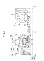
- the automatic transmission includes a torque converter 1 and a multiple stage transmission gear mechanism 10 for establishing selectively a shift gear stage among plural stages of different speed ratios.
- the torque converter 1 is provided with a pump 4 on a case 4 connected with an engine output shaft 2, a turbine 5 disposed facing the pump 4 and driven by the pump 4 through a hydraulic fluid and a stator 6 disposed between the pump 4 and the turbine 5 and supported by a transmission casing 11 through one-way clutch 7 for making a torque amplifying operation. Rotation of the turbine 5 is transmitted to the gear mechanism 10 through a turbine shaft 8.
- the torque converter 1 is further provided with a lock-up clutch 30 for engaging directly an input member with an output member of the torque converter 1. With the engine output shaft 2 is connected a shaft 9 passing through the turbine shaft 8. The shaft 9 drives an oil pump 90 disposed at a rear end portion of the transmission.
- the gear mechanism 10 includes a Ravigneaux-type planetary gear mechanism 12 having a small sun gear 13 movably mounted on the turbine shaft 8, a large sun gear 14 disposed rearward of the small sun gear 13 and movably mounted on the turbine shaft 8, a plurality of short pinion gears 15 meshed with the small sun gear 13, a long pinion gear 16 meshed with the short pinion gears 15 at a front portion and with the large sun gear 14 at a rear end portion thereof, a carrier 17 rotatably carrying the short and long pinion gears 15 and 15, and a ring gear 18 meshed with the long pinion gear 15.
- a forward clutch 20 for controlling a torque transmission to the small sun gear 13 through a first one-way clutch 22 and a coast clutch 21 for controlling the torque transmission between the turbine shaft 8 and the small sun gear 13 in a juxtaposed relationship.
- a 2-4 brake 23 having a brake drum 23a connected with the large sun gear 14 and a brake band 23b engaged with the brake drum 23a is disposed radially outward of the coast clutch 21. When the 2-4 brake is engaged, the large sun gear 14 is fixed.
- a reverse clutch 24 for making a reverse running is disposed adjacent to the 2-4 brake to control the torque transmission between the large sun gear 14 and the turbine shaft 8 through the brake drum 23a .
- a second one-way clutch 26 and a low & reverse brake 25 for engaging and disengaging the carrier 14 and the transmission casing 11 in a juxtaposed relationship.
- a 3-4 clutch for controlling the torque transmission between the carrier 17 and the turbine shaft 8.
- the gear mechanism 10 is provided with four shift gear stages in the forward direction and one shift gear stage in the reverse direction and selectively establishes one of the shift gear stages through operations of the clutches 20, 21, 24, 27 and brakes 23 and 25.
- Table 1 shows a relationship between the respective gear stages and operations of the frictional elements 20-27.
- (0) means that the corresponding element transmits the torque when it is used as a driving element.
- the lock-up clutch 30 of the torque converter 1 is provided with a torsion damper 31 and a damper piston 32 disposed between the turbine 5 and a converter cover 36 connected with the engine output shaft 2 for rotating integrally with the turbine shaft 8 and a frictional plate (not shown) provided on the converter cover 36 facing the damper piston 32.
- the damper piston 32 divides a space formed in the converter cover 36 into a R-chamber 33 adjacent to the turbine 5 and a F-chamber 34 adjacent to the converter cover 36.
- a hydraulic pressure Pr introduced into the R-chamber 33 as an engaging pressure urges the damper piston 32 toward the frictional plate of the converter cover 36 to engage the lock-up clutch 30.
- an engaging force of the lock-up clutch 30 is determined based on a pressure difference of the hydraulic pressure between the R-chamber and F-chamber.
- the torque converter 1 selectively takes a converter condition in which the engine torque is transmitted hydraulically to the gear mechanism 10 through only the torque converter 1, a lock-up condition in which the engine torque is transmitted mechanically to the gear mechanism 10 through only the lock-up clutch 30, and a slip condition in which the engine torque is transmitted hydraulically and mechanically through both the torque converter 1 and the lock-up clutch 30.
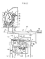
- a hydraulic control circuit 40 for the lock-up clutch 30 is provided with a lock-up shift valve 50 takes three different positions corresponding to the converter, lock-up and slip condition, adjusting valve 60 for controlling the hydraulic pressure Pf introduced into the F-chamber through the shift valve 50, an on-off solenoid valve 71 for making on-off operation of introduction of a first pilot pressure Ps for the shift valve 50, and a duty solenoid valve 72 for making a duty control to change a second pilot pressure Pd for the shift valve 50 and the adjusting valve 60.
- the hydraulic circuit 40 is formed with a torque converter line L1 into which a hydraulic pressure produced in an oil pump 90 is introduced as a line pressure after being regulated by a pressure regulator (not shown), a first pilot line L2 for supplying the first pilot pressure Ps, a second pilot line L3 for supplying the second pilot pressure Pd, a line L4 for supplying a predetermined hydraulic pressure Pc(for instance 4 kg/cm2 ), a line LR communicating a port 51R of the shift valve 50 with the R-chamber 33, a line LF communicating a port 51F of the shift valve 50 with the F-chamber 34.
- the line L1 is divided into a line L11 communicating with a port 52R of the shift valve 50 and a line L12 communicating with a port 62F of the adjusting valve 60.
- a port 61F of the adjusting valve 60 is communicated with a port 52F of the shift valve 50 through a line L13.
- a line L5 communicates a port 53 of the shift valve 50 with an oil cooler 75.
- the first pilot line L2 is divided into a line L21 communicating with a port 57 of the shift valve 50 and a line L22 communicating with a port 68 of the adjusting valve 60.
- the on-off solenoid valve 71 is disposed on a drain line L23 of the line L2 so that the drain line L23 is closed at off condition of the solenoid valve 71.
- the solenoid valve 71 is turned on, the line L23 is opened to drain hydraulic fluid in the line L2.
- the second pilot line L3 is divided into a line L31 communicating with a port 58 of the shift valve 50 and a line L32 communicating with a port 65 of the adjusting valve 60.
- the duty solenoid valve 72 is disposed on a drain line L33 of the second pilot line L3.
- the drain line L33 is closed.
- the solenoid valve 72 is on or when the duty ratio therefor is a value other than zero, the hydraulic fluid in the line L3 is drained.
- the second pilot pressure Pd is reduced as the duty ratio is increased.
- a line LC introduces the hydraulic fluid into the oil cooler 75 through a check valve 76 which is opened when a hydraulic pressure is increased beyond a predetermined value.
- the shift valve 50 is provided with a first spool 54 (right) and a second spool 55 (left) disposed in series in a sleeve thereof.
- a spring 56 is disposed leftward of the spool 55 and another spring 56a is disposed between the spools 54 and 55.
- the first pilot pressure Ps acts on a right end of the first spool 54 through the first pilot line L2, line L21 and the port 57.
- the second pilot pressure Pd acts on a left end of the second spool 55 through the second pilot line L3, the line L31 and the port 58.
- the right end of the first spool 54 is enlarged to provide a greater pressure area than the left end of the second spool 55.
- the predetermined pressure Pc is introduced between the first and second spools 54 and 55 through a port 59 and the line L4.
- the first pilot pressure Ps is high so that the shift valve 50 takes a first position wherein the first and second spools 54 and 55 are offset together toward leftside of the sleeve of the shift valve as shown in Figure 3.
- the port 51R is communicated with the port 53 and the port 51F is communicated with the port 52F.
- the first pilot pressure Ps is low whereas the second pilot pressure Pd takes a relatively high value so that the shift valve 50 takes a second position in which the first and second spools 54 and 55 are offset at the right end of the sleeve of the shift valve 50 as shown in Figure 4.
- the port 51R is communicated with the port 52R and the port 51F is communicated with a drain port.
- the second pilot pressure Pd is relatively small so that the spool 54 and the spool 55 are moved away from each other and offset toward the opposite ends of the sleeve of the shift valve 50 by virtue of the hydraulic pressure Pc introduced into the port 59. That is, the first spool 54 is positioned at right end and the second spool 55 is positioned at left end to establish a third position as shown in Figure 5. With, the third position, the port 51R is communicated with the port 52R and the port 51F is communicated with the port 52F.
- the adjusting valve 60 is provided with a spool 63 in a sleeve thereof.
- the spool 63 is urged rightward by a spring 64 as illustrated in the drawings.
- the hydraulic pressure Pd acts on a right end of the spool 63a as a pilot pressure through the second pilot line L3, line L32 and port 65.
- the spool 63 is formed with an intermediate land portion of which right stepped portion 63b is subjected to a hydraulic pressure in the Line L13 through a line L15 with an orifice and a port 66.
- the spool 63 is also formed with a left land portion of which left stepped portion 63c is subjected to the torque converter pressure of the line L12 through a line L16 with an orifice and port 67. Left end surface of the spool 63 is subjected to the first pilot pressure Ps in the first pilot line L2 through a line L22 and port 68.
- the spool 63 When the solenoid 71 is off, the spool 63 is positioned at a right end of the sleeve of the adjusting valve 60 by virtue of the first pilot pressure Ps acting on the left end surface thereof so that the port 61F is communicated with the port 62F.
- the solenoid 71 When the solenoid 71 is on, that is , when the first pilot pressure Ps is zero, the spool 63 is moved to a position where the second pilot pressure Pd acting on the right end surface and the hydraulic pressure acting on the stepped portion 63b leftwardly are balanced with the hydraulic pressure acting one the stepped portion 63c and a resilient force of the spring 64 rightwardly.
- the spool 63 When the second pilot pressure Pd is increased, the spool 63 is moved leftwardly to increase the communication between the port 61F to the line 13 and the drain port. On the other hand, when the second pilot pressure Pd is reduced, the spool 63 is moved rightwardly to increase the communication between the port 61F and the port 62F to thereby increase the releasing pressure Pf. It will be understood that the releasing pressure Pf is reduced as the second pilot pressure Pd is increased.
- What is selected among the converter condition, lock-up condition and slip conditions is determined in accordance with a driving condition, such as throttle opening, vehicle speed in light of a map (not shown) by means of a control unit (not shown).
- a driving condition such as throttle opening, vehicle speed in light of a map (not shown) by means of a control unit (not shown).
- control unit After determination of the condition to be established, the control unit produces the on-off signal to the solenoid valve 71 and the duty ratio signal to the solenoid valve 72 to operate the shift valve 50 and the adjusting valve 60 to establish a desired condition of the torque converter 1.
- the shift valve 50 takes the first position as shown in Figure 3 wherein the port 51R is communicated with the port 53 so that the hydraulic fluid in the R-chamber 33 is introduced into the oil cooler 75 through the lines LR and L5.
- the port 51F is communicated with the port 52F so that the hydraulic fluid is introduced into the F-chamber 34 through the converter line L1 and the adjusting valve 60, and the line L13.
- the lock-up clutch 30 is disengaged because the engaging pressure Pr in the R-chamber 33 is much smaller than the releasing pressure Pf so that the converter condition is established.
- the port 61F is freely communicated with the port 62F of the adjusting valve 60 so that the adjusting valve 60 allows a hydraulic pressure corresponding to a line pressure of a constant value, such as 6.5 kg/cm2, to be introduced into the F-chamber 34.
- the pressure difference dP as an engaging pressure between the pressures Pr and Pf is maintained at a constant negative value as shown in Figure 6 so as to establish the converter condition.
- the solenoid valve 71 When the lock-up condition is required, the solenoid valve 71 is turned on whereas the duty ratio of the solenoid valve 72 is maintained at the constant value (0%). Thus, the shift valve takes the second position as shown in Figure 4 so that the port 51R is communicated with the port 52R. As a result, the hydraulic fluid is introduced into the R-chamber 33 through the lines L11 and LR from the line L1. Concurrently the port 51F is communicated with the drain port so that the hydraulic fluid in the F-chamber 34 is drained. Thus, the pressure difference dP between the R-chamber and F-chamber is a constant value corresponding to the line pressure so that the lock-up clutch 30 is fully engaged to established the lock-up condition.
- the solenoid valve 71 When the lock-up condition is changed to the slip condition, the solenoid valve 71 is kept on while the duty ratio of the solenoid valve 72 is increased to a value more than 20%.
- the shift valve 50 takes the third position as shown in Figure 5 so that the port 51R is communicated with the port 52R to allow the hydraulic pressure Pr to be introduced into the R-chamber 33 and the port 51F is communicated with the port 52F to allow the hydraulic pressure Pf to be introduced into the F-chamber 34.
- the value of the hydraulic pressure Pf is controlled by means of the adjusting valve 60 which is controlled in accordance with the duty ratio of the solenoid valve 72.
- the releasing pressure Pf is relatively low. Thereafter, the pressure Pf is gradually increased as the duty ratio is increased.
- the pressure difference dP between the R-chamber 33 and the F-chamber 34 is controlled through the duty control for the solenoid valve 72 to change the engaging force of the lock-up clutch 30 in the illustrated slip control.
- the releasing pressure Pf' is increased as shown by a phantom line in Figure 8 .
- the hydraulic pressure Pf in the line L13 is reduced as the second pilot pressure Pd is increased shown by a real line in Figure 8.
- the releasing pressure Pf' is increased as the duty ratio is reduced.
- the second spool 55 is moved rightwardly in Figure 5 because of the increase of the second pilot pressure Pd so that the shift valve 50 is shifted to take the second position as shown in Figure 4. Therefore, the hydraulic pressure in the F-chamber would be abruptly changed around the duty ratio 20%. This would cause an abrupt change in the engaging force of the lock-up clutch 30.
- the hydraulic pressure Pf in the line L13 is controlled to be decreased as the second pilot pressure Pd is increased.
- the hydraulic pressure Pf in the F-chamber 34 is changed in accordance with the duty ratio as shown by the real line in Figure 8.
- the releasing pressure Pf does not make an abrupt change around the duty ratio 20% irrespective of the switching operation from the third position to the second position in the shift valve 50 and thus changes continuously.
- the pressure difference dP changes continuously in accordance with the change of the duty ratio which causes a mode change between the slip condition and the lock-up condition to accomplish a smooth change in the engaging force of the lock-up clutch 30. This prevents an abrupt raising in engine speed at the time of the mode change.
- the mode change between the converter condition and the lock-up condition may be made though the slip condition to suppress an abrupt change in the engaging force of the lock-up clutch 30 for thereby obviating a torque shock taking advantage of the above duty control as shown by the real lines in Figures 8 and 9.
- the hydraulic pressure produced in the oil pump is introduced into the port 52R of the shift valve 50 through the line L1 and a port 69 of and the port 62F of the adjusting valve 60 through a line L17 and a line L18 as the line pressure after being regulated by a pressure regulator R.
- the hydraulic pressure produced in the oil pump 90 is introduced into the shift valve 50 through a line L6 and a port 58a, though the lines L2, L3 and the port 59 and through the lines L2, L21 and the port 57, and into the adjusting valve 60 through the lines L2, L3, L32 and the port 65 as a control pressure after being regulated by a regulator C which makes a substantially constant pressure.
- the first pilot pressure Ps acting on the right end surface of the first spool 54 of the shift valve 50 is introduced into the port 57 through the line 21 and can be controlled by the solenoid valve 71.
- the second pilot pressure Pd is introduced directly into the port 58a through the line L6 separated from the line L2 just downstream of the regulator C and acting on the left end surface of the second spool 55 of the shift valve 50.
- the third pilot pressure Pc acting between the first and second spools 54 and 55 is introduced into the port 59 through the line L3 separated from the line L2 and can be controlled by the duty solenoid valve 72.
- the port 65 of the adjusting valve 60 is communicated with the line L3 through the line L32 so that the third pilot pressure Pc also acts on the right end surface 63a of the spool 63 of the adjusting valve 60.
- the line pressure introduced into the port 63 through the line L17 acts on a stepped portion 63d of the spool 63 in opposition to the third pilot pressure Pc.
- the line pressure from the regulator valve R is introduced into the F-chamber 34 through the line L1, line L18, port 62F, port 66, line L13, port 52F, port 51F and line LF as the releasing pressure Pf and can be changed by controlling the communication between the port 62F and the port 66 of the adjusting valve 60.
- the line pressure is introduced into the R-chamber 33 as the engaging pressure Pr through the line L1, port 52R, port 51R and the line LR.
- the solenoid valve 71 In operation, in the converter condition, the solenoid valve 71 is off to be closed and the solenoid valve 72 receives a duty ratio smaller than 20% to be substantially closed as well so that the control pressure regulated by the regulator C is introduced into the port 57 through the line L21 as the first pilot pressure Ps with a relatively high value. Concurrently, the control pressure is introduced into the port 59 of the shift valve 50 as the third pilot pressure Pc through the line L3 and into the port 65 of the adjusting valve 60. The control pressure is also normally introduced into the port 58a of the shift valve 50 through the line L6 as the second pilot pressure Pd.
- the spools 54 and 55 are positioned at the left end of the sleeve of the shift valve 50 in opposition to the resilient force of the spring 56 and reacting rightward forces acting on the spools 54 and 55 by virtue of the hydraulic pressure as shown by the real line in Figure 10 to establish the first position of the shift valve 50.
- the port 52F is communicated with the port 51F so that the line pressure is introduced into the F-chamber 34 as the releasing pressure Pf.
- the port 53 is communicated with the port 51R so that the hydraulic pressure in the R-chamber is reduced through the line L5.
- the control pressure introduced into the port 65 to act on the right end surface 63a of the spool 63 causes the spool 63 to be offset at the left end of the sleeve in opposition to the resilient force of the spring 64 and the line pressure acting on the stepped portion 63d as shown by the real line in Figure 10.
- the port 62F is fully communicated with the port 66 so that the line pressure is introduced into the F-chamber 34 without producing significant pressure drop.
- the pressure difference dP between the F-chamber (Pf) and the R-chamber (Pr) is increased to establish the converter condition.
- the solenoid valve 71 In the slip condition, the solenoid valve 71 is on to be opened and the duty solenoid valve 72 receives a duty signal ranged from about 20% to 80% so that the first pilot pressure Ps acting on the right end surface of the spool 54 is reduced through the port 57 and the hydraulic pressure introduced to the port 59 of the shift valve 50 and to the port 65 of the adjusting valve 60 is also reduced in proportion to increase of the duty ratio.
- the second spool is maintained at the same position as the converter condition whereas the first spool 54 is moved to the right end of the sleeve of the shift valve 50 as shown by a phantom line in Figure 10 away from the second spool 55 to establish the third position of the shift valve 50 because of the serious reduction of the first pilot pressure Ps.
- the port 52F remains communicated with the port 51F
- the port 51R is switched to be communicated with the port 52R from the communication with the port 53.
- the spool 63 is moved rightwardly in accordance with a balance of a rightward force by virtue of the sum of the resilient force of the spring 64 and the hydraulic pressure acting on the stepped portion through the port 69 and a leftward force by virtue of the hydraulic pressure acting on the right end surface of the spool 63 through the port 65 so as to reduce the communication between the port 62F and the port 66. Therefore, the releasing pressure Pf into the F-chamber 34 is reduced as increase of the duty ratio for the solenoid valve 72 whereas the engaging pressure Pr is increased because of the switching action of the communication of the port 51R from the port 53 to the port 52R.
- the lock-up clutch 30 establishes the slip condition wherein the slip rate or speed difference between the input member and output member is controlled to a target value in accordance with the duty ratio for the solenoid valve 72.
- the solenoid valve 71 In the lock-up condition, the solenoid valve 71 is maintained opened and the solenoid valve 72 receives a duty ratio more than about 80% to be substantially opened so that the hydraulic pressure Ps introduced into the port 57 of the shift valve 50 is low and the hydraulic pressure Pc introduced into the port 59 of the shift valve 54 and into the port 65 of the adjusting valve 60 is also low.
- the first and second spools 54 and 55 are offset at the right end of the sleeve of the shift valve 50 as shown by the phantom lines in Figure 10 because of the second pilot pressure Pd through the line L6 and the port 58a and the resilient force of the spring 56.
- the port 52R remains communicated with the port 51R whereas the communication between the port 52F and the port 51F is interrupted.
- the spool 63 is moved rightward to be positioned at the right end of the sleeve of the adjusting valve 60 as shown by the phantom line in Figure 10 because of the resilient force of the spring 64 so that the communication between the port 62F and the port 66 is entirely interrupted. With this position, the line pressure adjusted by the regulator R is introduced into the R-chamber 33 without producing a substantial pressure drop through the line L1, port 52R, port 51R and line LR.
- the port 51F is switched to be communicated with the drain port from the communication with the port 52F so that the hydraulic fluid in the F-chamber 34 is drained.
- the engaging pressure Pr in the R-chamber is much greater than the releasing pressure Pf in the F-chamber 34 enough to establish the lock-up condition.
- the pressure difference dP is increased as the increase of the duty ratio for the solenoid valve 72.
- the duty ratio takes a value more than d2 (for example 80%)
- the lock-up condition is established.
- the duty ratio takes a value less than d1 (for example 20%)
- the converter condition is established.
- the slip condition is established wherein the slip ratio is decreased as the duty ratio is increased.
- the switching action of the hydraulic fluid to and from the F-chamber is carried out in the shift valve 50 to change the mode between the lock-up condition and the slip condition when the releasing pressure Pf is low because of the limited communication between the port 62F and the port 66 of the adjusting valve 60. Therefore, the mode change can be smoothly made with suppressing the abrupt change in the releasing pressure Pf in the F-chamber. Thus, the abrupt change in the engaging force of the lock-up clutch 30 is also prevented.
- the shift valve 50 and the adjusting valve 60 are controlled by an electronic control unit (not shown) through the solenoid valves 71 and 72 virtually.
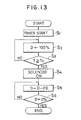
- step S1 the control unit starts a timer (step S1), sets a duty ratio signal D at a value 100% for the duty solenoid valve 72 (step S2) and repeats the steps S1 and S2.
- step S2 the duty solenoid value 72 drains the second pilot line L3 entirely.
- the control unit judges whether or not a counting value T of the timer reaches a predetermined value T0.
- step S4 is carried out to turn on the solenoid valve 71 (step S4).
- the control unit changes the duty ratio D by subtracting a predetermined value dD until the value D reaches zero % (steps S5, S6).
- the solenoid 71 is turned on when the predetermined value T0 has passed and thereafter the duty ratio starts to be decreased from the value 100% as shown Figure 14.
- the shift valve 50 takes the third position in which the slip condition is established.
- the actuation of the solenoid valve 71 is deferred by the predetermined value T0 after the duty ratio of 100 % is provided for the solenoid valve 72.
- the pilot line L3 is drained entirely prior to draining the line L2 because of the time lag T0. Therefore, it is prevented that the lock-up condition is undesirably established temporarily by virtue of the remaining pressure in the pilot line 3 to produce a temporary soaring of the engaging force when the mode is changed from the converter condition to the slip condition as shown in Figure 15.
- the duty ratio is decreased from 100%, the engaging force of the lock-up clutch 30 is gradually increased and eventually the lock-up condition is accomplished when the duty ratio is zero.
Landscapes
- Engineering & Computer Science (AREA)
- General Engineering & Computer Science (AREA)
- Mechanical Engineering (AREA)
- Control Of Fluid Gearings (AREA)
Applications Claiming Priority (6)
| Application Number | Priority Date | Filing Date | Title |
|---|---|---|---|
| JP103995/90 | 1990-04-18 | ||
| JP2103995A JP2874952B2 (ja) | 1990-04-18 | 1990-04-18 | 流体継手の締結力制御装置 |
| JP104216/90 | 1990-04-19 | ||
| JP10421690A JP2878384B2 (ja) | 1990-04-19 | 1990-04-19 | 流体継手の締結力制御装置 |
| JP26139690A JPH04140569A (ja) | 1990-09-28 | 1990-09-28 | 流体継手のロックアップ制御装置 |
| JP261396/90 | 1990-09-28 |
Publications (3)
| Publication Number | Publication Date |
|---|---|
| EP0452887A2 true EP0452887A2 (de) | 1991-10-23 |
| EP0452887A3 EP0452887A3 (en) | 1992-01-29 |
| EP0452887B1 EP0452887B1 (de) | 1995-08-16 |
Family
ID=27310124
Family Applications (1)
| Application Number | Title | Priority Date | Filing Date |
|---|---|---|---|
| EP91106063A Expired - Lifetime EP0452887B1 (de) | 1990-04-18 | 1991-04-16 | Steuerungssystem für ein Momentwandler |
Country Status (4)
| Country | Link |
|---|---|
| US (1) | US5339935A (de) |
| EP (1) | EP0452887B1 (de) |
| KR (1) | KR940006116B1 (de) |
| DE (1) | DE69112109T2 (de) |
Cited By (7)
| Publication number | Priority date | Publication date | Assignee | Title |
|---|---|---|---|---|
| EP0707165A3 (de) * | 1994-10-14 | 1997-09-03 | Ford Motor Co | Automatisches Mehrganggetriebe mit Drehmomentwandler |
| EP0707162A3 (de) * | 1994-10-14 | 1997-11-19 | Ford Motor Company Limited | Automatisches Mehrganggetriebe und Steuersystem dafür |
| US5701982A (en) * | 1994-07-11 | 1997-12-30 | Nippondenso Co., Ltd. | Lockup control system for automatic transmission |
| EP0754890A3 (de) * | 1995-07-17 | 1998-04-01 | Toyota Jidosha Kabushiki Kaisha | System zur Regelung des Schlupfes einer Ueberbrückungskupplung |
| EP0791768A3 (de) * | 1996-02-20 | 1998-06-24 | Ford Motor Company | Drehmomentwandler- Regeler und Überbrückungs-Kupplungssperrsystem für ein Kraftfahrzeug |
| EP0814285A3 (de) * | 1996-06-07 | 1999-12-08 | Ford Motor Company Limited | Automatisches Mehrganggetriebe und Drehmomentwandler mit Überbrückungskupplung |
| US8052577B2 (en) | 2004-08-20 | 2011-11-08 | Nt Consulting International Pty Ltd | Torque converter |
Families Citing this family (14)
| Publication number | Priority date | Publication date | Assignee | Title |
|---|---|---|---|---|
| US5518091A (en) * | 1992-12-03 | 1996-05-21 | Volkswagen Ag | Slide valve for controlling a bridging clutch in an automatic transmission |
| JP3218839B2 (ja) * | 1994-03-03 | 2001-10-15 | 日産自動車株式会社 | 自動変速機の作動流体冷却装置 |
| JPH09133158A (ja) * | 1995-11-10 | 1997-05-20 | Toyota Motor Corp | 湿式摩擦係合装置 |
| JP3791716B2 (ja) * | 1996-06-06 | 2006-06-28 | 株式会社デンソー | 自動変速機用油圧制御装置 |
| JP3787921B2 (ja) * | 1996-10-24 | 2006-06-21 | アイシン精機株式会社 | トルクコンバータのロックアップ油圧制御装置 |
| JP3496410B2 (ja) * | 1996-10-30 | 2004-02-09 | 日産自動車株式会社 | 自動変速機のロックアップ時ライン圧制御装置 |
| JP3635190B2 (ja) * | 1997-07-09 | 2005-04-06 | 日産自動車株式会社 | 自動変速機の油圧制御装置 |
| US6990996B2 (en) * | 2002-04-29 | 2006-01-31 | Sonnax Industries, Inc. | Torque converter clutch regulator valve assembly and method of installation |
| US7104273B1 (en) | 2003-04-28 | 2006-09-12 | Sonnax Industries, Inc. | Torque converter clutch regulator valve assembly and method of installation |
| US8061463B2 (en) * | 2004-11-25 | 2011-11-22 | Honda Motor Co., Ltd. | Control system for hybrid vehicle |
| JP4238916B2 (ja) * | 2007-01-12 | 2009-03-18 | トヨタ自動車株式会社 | ロックアップクラッチの油圧供給装置 |
| US9234583B2 (en) * | 2007-07-17 | 2016-01-12 | Ford Global Technologies, Llc | Hydraulic supply system for torque converter impeller clutch |
| JP5177026B2 (ja) * | 2009-03-12 | 2013-04-03 | アイシン・エィ・ダブリュ株式会社 | 自動変速機の油圧制御装置 |
| JP2011021696A (ja) * | 2009-07-16 | 2011-02-03 | Aisin Seiki Co Ltd | 流体伝動装置の油圧制御装置 |
Family Cites Families (6)
| Publication number | Priority date | Publication date | Assignee | Title |
|---|---|---|---|---|
| US2728427A (en) * | 1951-11-28 | 1955-12-27 | Studebaker Packard Corp | Transmissions |
| JPS6084464A (ja) * | 1983-10-14 | 1985-05-13 | Nissan Motor Co Ltd | 自動変速機の油圧制御装置 |
| JPS62297567A (ja) * | 1986-06-16 | 1987-12-24 | Honda Motor Co Ltd | 車両用変速機における流体トルクコンバ−タ用クラツチの作動制御方法 |
| US4880090A (en) * | 1987-06-11 | 1989-11-14 | Aisin-Warner Kabushiki Kaisha | Hydraulic controlling system for lockup clutches |
| JPH0745906B2 (ja) * | 1988-10-31 | 1995-05-17 | マツダ株式会社 | 流体継手のスリップ制御装置 |
| JPH02225875A (ja) * | 1988-11-04 | 1990-09-07 | Mazda Motor Corp | トルクコンバータのスリップ制御装置 |
-
1991
- 1991-04-16 DE DE69112109T patent/DE69112109T2/de not_active Expired - Fee Related
- 1991-04-16 EP EP91106063A patent/EP0452887B1/de not_active Expired - Lifetime
- 1991-04-18 KR KR1019910006183A patent/KR940006116B1/ko not_active Expired - Fee Related
-
1992
- 1992-08-13 US US07/928,165 patent/US5339935A/en not_active Expired - Lifetime
Cited By (8)
| Publication number | Priority date | Publication date | Assignee | Title |
|---|---|---|---|---|
| US5701982A (en) * | 1994-07-11 | 1997-12-30 | Nippondenso Co., Ltd. | Lockup control system for automatic transmission |
| EP0692656B1 (de) * | 1994-07-11 | 1998-06-10 | Denso Corporation | Steuerungssysteme für die Überbrückungskupplung eines Momentwandlers |
| EP0707165A3 (de) * | 1994-10-14 | 1997-09-03 | Ford Motor Co | Automatisches Mehrganggetriebe mit Drehmomentwandler |
| EP0707162A3 (de) * | 1994-10-14 | 1997-11-19 | Ford Motor Company Limited | Automatisches Mehrganggetriebe und Steuersystem dafür |
| EP0754890A3 (de) * | 1995-07-17 | 1998-04-01 | Toyota Jidosha Kabushiki Kaisha | System zur Regelung des Schlupfes einer Ueberbrückungskupplung |
| EP0791768A3 (de) * | 1996-02-20 | 1998-06-24 | Ford Motor Company | Drehmomentwandler- Regeler und Überbrückungs-Kupplungssperrsystem für ein Kraftfahrzeug |
| EP0814285A3 (de) * | 1996-06-07 | 1999-12-08 | Ford Motor Company Limited | Automatisches Mehrganggetriebe und Drehmomentwandler mit Überbrückungskupplung |
| US8052577B2 (en) | 2004-08-20 | 2011-11-08 | Nt Consulting International Pty Ltd | Torque converter |
Also Published As
| Publication number | Publication date |
|---|---|
| EP0452887A3 (en) | 1992-01-29 |
| DE69112109T2 (de) | 1996-04-18 |
| US5339935A (en) | 1994-08-23 |
| KR910018703A (ko) | 1991-11-30 |
| EP0452887B1 (de) | 1995-08-16 |
| DE69112109D1 (de) | 1995-09-21 |
| KR940006116B1 (ko) | 1994-07-06 |
Similar Documents
| Publication | Publication Date | Title |
|---|---|---|
| US5339935A (en) | Control system for torque converter | |
| US4989702A (en) | Control system for torque converter of automatic transmission | |
| US4513639A (en) | Creeping preventing apparatus in automatic transmission for vehicle | |
| US5439427A (en) | Multiple stage automatic transmission | |
| US4369865A (en) | Lock-up control system for a torque converter | |
| US3890856A (en) | Creep preventing hydraulic control circuit for vehicle automatic transmission | |
| EP0059425A2 (de) | Schaltvorrichtung bei einer hydraulischen Steuereinrichtung eines automatischen Getriebes | |
| US4709596A (en) | Control of a vehicle automatic transmission | |
| US4633739A (en) | System for controlling automatic transmission having communication control valve means | |
| US4462280A (en) | Manual valve for hydraulic control system for automatic transmission | |
| JP3478438B2 (ja) | 自動変速機の油圧制御装置 | |
| US5435211A (en) | Control system for torque converter | |
| EP0725239B1 (de) | Steuerung für ein hydraulisch betätigtes Kraftfahrzeuggetriebe | |
| US5109734A (en) | Hydraulic control system for an automatic transmission | |
| US5224399A (en) | Control system for automatic transmission | |
| US5176046A (en) | Control system for an automatic transmission | |
| JP3342167B2 (ja) | 自動変速機の油圧制御装置 | |
| US4691596A (en) | Automatic transmission with anti creep device | |
| EP0195295B1 (de) | Steuersystem für ein mehrgängiges Getriebe mit sperrbarem Drehmomentwandler | |
| JPH0621651B2 (ja) | 車両自動変速機の制御装置 | |
| JPS6148026B2 (de) | ||
| JP2874952B2 (ja) | 流体継手の締結力制御装置 | |
| US5634864A (en) | Hydraulic control apparatus for hydraulically operated vehicular transmission | |
| JPH09177959A (ja) | 自動変速機の制御装置 | |
| JP2847742B2 (ja) | 自動変速機の制御装置 |
Legal Events
| Date | Code | Title | Description |
|---|---|---|---|
| PUAI | Public reference made under article 153(3) epc to a published international application that has entered the european phase |
Free format text: ORIGINAL CODE: 0009012 |
|
| AK | Designated contracting states |
Kind code of ref document: A2 Designated state(s): DE FR GB |
|
| PUAL | Search report despatched |
Free format text: ORIGINAL CODE: 0009013 |
|
| AK | Designated contracting states |
Kind code of ref document: A3 Designated state(s): DE FR GB |
|
| 17P | Request for examination filed |
Effective date: 19920323 |
|
| 17Q | First examination report despatched |
Effective date: 19930719 |
|
| GRAA | (expected) grant |
Free format text: ORIGINAL CODE: 0009210 |
|
| AK | Designated contracting states |
Kind code of ref document: B1 Designated state(s): DE FR GB |
|
| REF | Corresponds to: |
Ref document number: 69112109 Country of ref document: DE Date of ref document: 19950921 |
|
| ET | Fr: translation filed | ||
| PGFP | Annual fee paid to national office [announced via postgrant information from national office to epo] |
Ref country code: GB Payment date: 19960409 Year of fee payment: 6 |
|
| PGFP | Annual fee paid to national office [announced via postgrant information from national office to epo] |
Ref country code: FR Payment date: 19960410 Year of fee payment: 6 |
|
| PLBE | No opposition filed within time limit |
Free format text: ORIGINAL CODE: 0009261 |
|
| STAA | Information on the status of an ep patent application or granted ep patent |
Free format text: STATUS: NO OPPOSITION FILED WITHIN TIME LIMIT |
|
| 26N | No opposition filed | ||
| PG25 | Lapsed in a contracting state [announced via postgrant information from national office to epo] |
Ref country code: GB Effective date: 19970416 |
|
| GBPC | Gb: european patent ceased through non-payment of renewal fee |
Effective date: 19970416 |
|
| PG25 | Lapsed in a contracting state [announced via postgrant information from national office to epo] |
Ref country code: FR Free format text: LAPSE BECAUSE OF NON-PAYMENT OF DUE FEES Effective date: 19971231 |
|
| REG | Reference to a national code |
Ref country code: FR Ref legal event code: ST |
|
| PGFP | Annual fee paid to national office [announced via postgrant information from national office to epo] |
Ref country code: DE Payment date: 20090409 Year of fee payment: 19 |
|
| PG25 | Lapsed in a contracting state [announced via postgrant information from national office to epo] |
Ref country code: DE Free format text: LAPSE BECAUSE OF NON-PAYMENT OF DUE FEES Effective date: 20101103 |