EP0453017B1 - Insassen-Rückhaltesystem - Google Patents
Insassen-Rückhaltesystem Download PDFInfo
- Publication number
- EP0453017B1 EP0453017B1 EP91200745A EP91200745A EP0453017B1 EP 0453017 B1 EP0453017 B1 EP 0453017B1 EP 91200745 A EP91200745 A EP 91200745A EP 91200745 A EP91200745 A EP 91200745A EP 0453017 B1 EP0453017 B1 EP 0453017B1
- Authority
- EP
- European Patent Office
- Prior art keywords
- wall portion
- cushion
- support
- upper wall
- pressure fluid
- Prior art date
- Legal status (The legal status is an assumption and is not a legal conclusion. Google has not performed a legal analysis and makes no representation as to the accuracy of the status listed.)
- Expired - Lifetime
Links
- 239000012530 fluid Substances 0.000 claims description 29
- 230000000903 blocking effect Effects 0.000 claims 1
- 238000007789 sealing Methods 0.000 claims 1
- 239000007789 gas Substances 0.000 description 6
- 239000000463 material Substances 0.000 description 4
- 229920003023 plastic Polymers 0.000 description 3
- 239000004033 plastic Substances 0.000 description 3
- 230000003111 delayed effect Effects 0.000 description 2
- 230000001133 acceleration Effects 0.000 description 1
- 239000002184 metal Substances 0.000 description 1
Images
Classifications
-
- B—PERFORMING OPERATIONS; TRANSPORTING
- B60—VEHICLES IN GENERAL
- B60R—VEHICLES, VEHICLE FITTINGS, OR VEHICLE PARTS, NOT OTHERWISE PROVIDED FOR
- B60R21/00—Arrangements or fittings on vehicles for protecting or preventing injuries to occupants or pedestrians in case of accidents or other traffic risks
- B60R21/02—Occupant safety arrangements or fittings, e.g. crash pads
- B60R21/16—Inflatable occupant restraints or confinements designed to inflate upon impact or impending impact, e.g. air bags
- B60R21/20—Arrangements for storing inflatable members in their non-use or deflated condition; Arrangement or mounting of air bag modules or components
- B60R21/203—Arrangements for storing inflatable members in their non-use or deflated condition; Arrangement or mounting of air bag modules or components in steering wheels or steering columns
- B60R21/2035—Arrangements for storing inflatable members in their non-use or deflated condition; Arrangement or mounting of air bag modules or components in steering wheels or steering columns using modules containing inflator, bag and cover attachable to the steering wheel as a complete sub-unit
-
- B—PERFORMING OPERATIONS; TRANSPORTING
- B60—VEHICLES IN GENERAL
- B60R—VEHICLES, VEHICLE FITTINGS, OR VEHICLE PARTS, NOT OTHERWISE PROVIDED FOR
- B60R21/00—Arrangements or fittings on vehicles for protecting or preventing injuries to occupants or pedestrians in case of accidents or other traffic risks
- B60R21/02—Occupant safety arrangements or fittings, e.g. crash pads
- B60R21/16—Inflatable occupant restraints or confinements designed to inflate upon impact or impending impact, e.g. air bags
- B60R21/26—Inflatable occupant restraints or confinements designed to inflate upon impact or impending impact, e.g. air bags characterised by the inflation fluid source or means to control inflation fluid flow
-
- B—PERFORMING OPERATIONS; TRANSPORTING
- B60—VEHICLES IN GENERAL
- B60R—VEHICLES, VEHICLE FITTINGS, OR VEHICLE PARTS, NOT OTHERWISE PROVIDED FOR
- B60R21/00—Arrangements or fittings on vehicles for protecting or preventing injuries to occupants or pedestrians in case of accidents or other traffic risks
- B60R21/02—Occupant safety arrangements or fittings, e.g. crash pads
- B60R21/16—Inflatable occupant restraints or confinements designed to inflate upon impact or impending impact, e.g. air bags
- B60R21/26—Inflatable occupant restraints or confinements designed to inflate upon impact or impending impact, e.g. air bags characterised by the inflation fluid source or means to control inflation fluid flow
- B60R21/261—Inflatable occupant restraints or confinements designed to inflate upon impact or impending impact, e.g. air bags characterised by the inflation fluid source or means to control inflation fluid flow with means other than bag structure to diffuse or guide inflation fluid
Definitions
- This invention relates to an inflatable occupant restraint system as specified in the preamble of claim 1, for example as disclosed in US-A-4,902,036. More particularly, this invention concerns an inflatable occupant restraint system which releasably secures the inflatable cushion against initial deployment normal to, i.e., towards, the occupant and directs such initial deployment laterally of, i.e., planar to, the occupant.
- An occupant restraint system according to the present invention is characterised by the features specified in the characterising portion of claim 1.
- the restraint system of this invention avoids engagement of the cushion and occupant during the initial deployment stage by releasably securing the cushion against initial deployment normal to, i.e., towards, the occupant and directing such initial deployment laterally of, i.e., planar to, the occupant. After initial deployment of the cushion has occurred, the securement is released and the cushion deploys normal to, i.e., towards, the occupant.
- the restraint system includes a known restraint module having a support, an enclosure mounted on the support, a folded occupant restraint cushion mounted on the support and located within the enclosure, and a gas generator or source of pressure fluid mounted on the support within the enclosure and communicating with the interior of the folded cushion.
- the cushion is folded to provide a substantially planar upper wall portion of substantially rectangular shape, a lower wall portion, fan-folded longer side wall portions, and pleat-folded end wall portions which are turned under the fan-folded side wall portions.
- the side wall and end wall portions connect the upper and lower wall portions.
- the restraint system of this invention additionally includes a planar reaction member of the general size of the upper wall portion of the cushion and located within the folded cushion between the upper wall portion and the first, distal, inwardly-directed folds of the fan-folded side wall portions.
- the reaction member is mounted to the support.
- a clamping securement member clamps the first, distal folds of the fan-folded side wall portions to the lower side of the reaction member.
- the reaction member blocks impingement of the pressure fluid from the gas generator on the upper wall portion of the cushion.
- the clamping of the first, distal folds of the fan-folded side wall portions of the cushion to the lower side of the reaction member blocks the pressure fluid from flowing between said folds and around the sides of the reaction member to the upper side thereof and underneath the upper wall portion of the cushion.
- the pleat-folded end wall portions provide a tortuous path and effectively block the pressure fluid from flowing around the ends of the reaction member to the upper side thereof. Thus, no pressure fluid can impinge on the upper wall portion and the upper wall portion remains stationary during the initial stage of deployment of the cushion.
- the first, distal folds of the cushion are pulled outwardly and away from the lower side of the reaction member to permit the pressure fluid to impinge on the upper wall portion of the cushion around the reaction member as the distal folds unfold relative to the side and upper wall portions.
- the impingement of the pressure fluid on the upper wall portion initiates deployment of the cushion through outwardly-opening separable flaps in the upper wall of the enclosure as the pleat-folded end wall portions unfold, to provide the upper, outer wall of the cushion which moves normal to, i.e., towards, the occupant.
- the subsequent engagement of the occupant and said upper, outer wall during such movement provides the occupant restraint.
- the primary feature of this invention is that it provides an occupant restraint system which releasably secures an inflatable occupant restraint cushion against movement normal to, i.e., towards, an occupant during the initial stage of deployment of the cushion.
- the cushion is deployed in directions laterally of, i.e., planar to, the occupant during the initial deployment stage.
- the wall of the cushion engageable by the occupant is releasably secured against movement normal to, i.e., towards, the occupant during the initial deployment stage.
- said wall of the cushion is released when the volume and pressure of the inflating pressure fluid build up to a predetermined level.
- the cushion is folded to provide an upper wall portion, fan-folded side wall portions and pleat-folded end wall portions, with the distal folds of the fan-folded side wall portions being releasably clamped to a reaction member.
- the reaction member is planar, of the general size of the upper wall portion of the folded cushion, and has its upper side engaging said upper wall portion and its lower side clamped to the distal folds of the fan-folded side wall portions.
- the reaction member is mounted to the support for the cushion.
- the clamping force is provided by a clamping member mounted to the lower side of the reaction member.
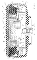
- an occupant restraint system 20 is shown mounted in a conventional manner to a hub portion 22 of a vehicle steering wheel 24.
- the hub portion includes a splined bushing 26 which receives an upper splined end of a vehicle steering shaft 28 and is bolted thereto at 30 to secure the steering wheel to the vehicle steering system.
- a substantially rectangularly-shaped support plate 32 has a central, circular opening 34.
- a flange 36 of a conventional inflator 38 seats against a lower side of the plate 32 and is secured thereto in a conventional manner.
- An upper outlet portion 40 of the inflator projects through the plate 32 and into the interior of a folded inflatable driver restraint cushion 42.
- the cushion 42 includes upper and lower circular members 44 and 46 which are secured together at their circular edge portions.
- the upper cushion member 44 provides the impact surface of the cushion for the driver when the cushion is inflated, and the lower cushion member 46 has a central opening 48 which receives the upper outlet portion 40 of the gas generator therethrough.
- a ring 50 is fastened at 52 to the plate 32 around the opening 34 therein to clamp the cushion member 46 to the plate 32 around the opening 48 therethrough.
- the inflator 38 is a gas generator which is electrically actuated from a conventional electrical power source when acceleration or velocity or other type sensors sense the impact of the vehicle with an obstacle or the possibility or probability of such an impact.
- sensors and the circuits connecting the sensors to a power source are well-known in the art.
- inflators of the gas-generating type are also well-known in the art.
- a container 54 for the cushion 42 is formed of plastics material and has a substantially box-like, rectangular shape.
- the container 54 houses the folded cushion 42 and has a flange 56 which underlies the plate 32 and has lateral flange segments 58 therealong.
- An outer decorative cover 60 of plastics material is of the same general shape as the container 54.
- the cover 60 has a flange 62 which overlies the flange 56 of the container.
- a retainer 64 overlies the flanges 56 and 62 and is fastened at 66 to the support plate 32 to secure the container 54 and cover 60 to the support plate 32.
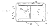
- the cover 60 is provided with a moulded-in line 68 in its upper wall which also extends along the longer side walls of the cover 60 to provide the upper wall with oppositely-opening separable flaps 69 and provide the longer side walls with oppositely-opening separable flaps 70.
- the container 54 is provided with lines of perforations which provide like flaps in the upper and longer side walls thereof. The details of the container 54 and the cover 60, and the manner in which each separates into flaps during deployment of the cushion 42 are disclosed in the aforenoted European application EP-A-0 370 613. Such disclosure is incorporated herein by reference.
- the plate 32 thus mounts the inflator 38, the cushion 42, the container 54, and the cover 60 to provide the modular restraint system 20.
- the folds 74 as a unit are then tucked under or folded under respective ends of a last, proximal fold 76 of folds 72 rather than extending from the folds 72 as shown in the aforenoted European application EP-A-0 370 613.
- the folded cushion thus has fan-folded side wall portions and pleat-folded end wall portions.
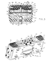
- a reaction plate member 80 of the general size of an upper wall portion 82 of the folded cushion is located between said upper wall portion and the first, distal folds 84 of the folds 72 of the fan-folded side wall portions.
- the reaction member 80 is generally planar and formed of metal or other material which will withstand the temperature and pressure of the gases generated by the inflator 38.
- the reaction member 80 is located within the folded cushion by a pair of pin struts 86 which have their lower ends secured to the ring 50 and their upper ends secured to the reaction member 80.
- a clamping member 88 of plastics material is fastened at 90 to the underside of the reaction member 80 along the longitudinal centre-line of both members.
- the clamping member is of a smaller size than the reaction member and has its unsecured longitudinal portions underlying and clamping the first, distal folds 84 to the underside of the reaction member 80 with a predetermined force.
- the reaction member 80, the clamping member 88, the struts 86 and the ring 50 are assembled as a unit and then inserted into the interior of the folded cushion through the opening 48 in the lower cushion member 46.
- the ring 50 is then attached around the opening 48 to the plate 32 co-axial with the plate opening 34, and then the inflator 38 is fixed within the plate opening 34 to provide the assembly shown in Figure 4.
- This assembly is then housed within the container 54 and the cover 60 with the fan-folded side wall portions opposite the longer side walls and the pleat-folded end portions opposite the shorter side walls of the container 54 and the cover 60.
- the completed occupant restraint system is assembled in overlying relationship to the hub portion 22 by fasteners, not shown, which extend upwardly through openings in the hub portion and into tapped struts 92 which are secured to embossments 94 of the plate 32.
- the inflator When the inflator receives an appropriate signal, the inflator generates gas or pressure fluid which is fed into the interior of the folded cushion 42 through the upper outlet portion 40 of the inflator.
- the pressure fluid initiates unfolding of the folds 72 of the fan-folded side wall portions of the cushion 42 to initiate deployment of the cushion through the separable flaps 70 in the longer side walls of the container 54 and cover 60.
- the upper wall portion 82 of the cushion 42 remains stationary since the clamping of the first, distal folds 84 to the reaction member 80 by the clamping member 88 prevents the pressure fluid from flowing around the sides of the reaction member 80 and impinging on said upper wall portion 82.
- the tortuous paths provided by the folds 74 of the pleat-folded end wall portions prevent the pressure fluid from flowing around the ends of the reaction member 80 and impinging on the upper wall portion 82 of the cushion.
- the upper wall portion 82 of the cushion remains stationary and the cushion is initially deployed laterally of the occupant through the longer side walls of the container 54 and cover 60 through the separable flaps 70.
- the first, distal folds 84 are pulled outwardly from between the clamping member 88 and the reaction member 80 and begin to unfold into continuations of the other folds 72 and the upper wall portion 82 of the cushion as the pressure fluid impinges on the folds 84 and the upper wall portion 82.
- the unfolding of the folds 84 and the impingement of the pressure fluid on the upper wall portion 82 initiate deployment of the cushion normal to the occupant through the upper walls of the container and cover as the separable flaps 69 separate and open outwardly and oppositely of each other.
- the deployment of the cushion normal to, i.e., towards, the occupant is delayed and occurs subsequent to the deployment of the cushion laterally of, i.e., planar to, the occupant.
- the engagement of the cushion and occupant as the cushion deploys normal to, i.e., towards, the occupant provides the occupant restraint.
- the securing force of the clamping member 88 can be varied as desired in order to predetermine the delay in deployment of the cushion normal to, i.e., towards, the occupant.
- the aforenoted European application EP-A-0 370 613 shows various embodiments of separable flaps in the upper and longer side walls of the container and cover. The restraint system of this invention can be used with each of these embodiments.
- this invention provides an inflatable occupant restraint system which releasably secures an inflatable occupant restraint cushion against deployment normal to, i.e., towards, the occupant and directs such initial deployment laterally of, i.e., planar to, the occupant.
- the securement of the cushion is released at a predetermined time to permit deployment of the cushion normal to, i.e., towards, the occupant, so as to delay the engagement of the occupant and cushion until after initial deployment of the cushion.
Landscapes
- Engineering & Computer Science (AREA)
- Mechanical Engineering (AREA)
- Physics & Mathematics (AREA)
- Fluid Mechanics (AREA)
- Air Bags (AREA)
Claims (7)
- Ein Insassenrückhaltesystem (20) das umfaßt: einen Träger (32), ein Insassenrückhaltekissen (42), das einen unteren Wandteil (46) beinhaltet, der an dem Träger (32) angebracht ist, einen oberen Wandteil (44), der vom Träger (32) beabstandet ist, und gefaltete Seitenwandteile (72), die die oberen und unteren Wandteile (44, 46) miteinander verbinden, eine auf dem Träger (32) angebrachte und sich zum Inneren des Kissens durch den unteren Wandteil (46) öffnende Quelle von Druckfluid, um das Kissen (42) zu entfalten, und ein Druckfluidreaktionsmittel (80), das einen direkten Aufprall des Druckfluids gegen eine innere Oberfläche des Kissens (42) verhindert,
dadurch gekennzeichnet,
daß das Druckfluidreaktionsmittel (80) den oberen Wandteil (44) abdeckt, um den Aufprall von Druckfluid dort dagegen zu verhindern; wobei es ein Trägermittel (86) gibt, das das Reaktionsmittel (80) auf dem Träger (32) in überlagernd beabstandeter Beziehung zu der Quelle (38) des Druckfluids haltert; und wobei es ein Festhalte-Mittel (72, 88) gibt, welches lösbar den Raum zwischen dem Reaktionsmittel (80) und dem oberen Wandteil (44) des Kissens (42) gegen Eintritt des Druckfluids während der anfänglichen Entfaltung des Kissens abdichtet, so daß eine solche anfängliche Entfaltung auf eine Entfaltung lateral zu dem Reaktionsmittel (80) durch die Entfaltung von deren gefalteten Seitenwandteile (72) und Endwandteile (74) beschränkt ist, während das obere Wandteil (44) im wesentlichen ortsfest erhalten bleibt. - Ein Insassenrückhaltesystem (20) nach Anspruch 1, in welchem das Reaktionsmittel ein im wesentlichen ebenes Glied (80) im wesentlichen von derselben Größe wie der obere Wandteil (44) ist.
- Ein Insassenrückhaltesystem (20) nach Anspruch 1 oder 2, in welchem die Quelle für das Druckfluid eine auf dem Träger (32) angebrachte Aufblasvorrichtung (38) ist und das Trägermittel Streben (86) umfasst, die sich zwischen dem Reaktionsmittel (80) und dem Träger (32) benachbart der Aufblasvorrichtung (38) erstrecken.
- Ein Insassenrückhaltesystem (20) nach Anspruch 1, in welchem das Reaktionsmittel ein ebenes Glied (80) im wesentlichen derselben Größe wie der obere Randteil (44) beinhaltet, welches zwischen dem oberen Wandteil (44) und den distalen Teilen (84) des gefalteten Seitenwandteils (72) und des Endwandteils (74) des Kissens (42) angeordnet ist.
- Ein Insassenrückhaltesystem (20) nach Anspruch 1, in welchem das Rückhaltemittel ein ebenes Glied (80) beinhaltet, dessen Kantenteile an den oberen Wandteil (44) durch das Festhalte-Mittel (72, 88) abgedichtet sind.
- Ein Insassenrückhaltesystem (20) nach Anspruch 1, in welchem der Träger (32) eine Öffnung (34) hat; die Quelle (38) des Druckfluids sich durch die Trägeröffnung (34) erstreckt; der untere Wandteil (46) auf dem Träger (32) benachbart der Öffnung (34) angebracht ist; die Seitenwandteile fächer-gefaltete Seitenwandteile (72) sind, die die oberen und unteren Wandteile (44, 46) verbinden und eine Anzahl von Fächerfalten beinhalten; das Reaktionsmittel eine zwischen dem oberen Wandteil (44) und den distalen Falten (84) der Seitenwandteile angeordnete Reaktionsplatte (80) ist; das Trägermittel (86) sich zwischen der Platte (80) und dem Träger (32) erstreckt; und das zur Festhalte-Mittel ein an der Platte (80) angebrachtes Klammer-Glied (88) beinhaltet, welches die distalen Falten (84) der Seitenwandteile an die Platte (80) klammert, um den Fluß von Druckfluid um die Reaktionsplatte (80) herum zu dem oberen Wandteil (44) des Kissens (42) zu blockieren, und den oberen Wandteil (44) während der anfänglichen Entfaltung des Kissens (42) ortsfest hält.
- Ein Insassenrückhaltesystem nach Anspruch 6, in welchem der Endwandteil falten-gefaltete Endwandteile (74) umfasst, welche unter das Oberwandteil (44) als eine Einheit gefaltet sind; die Reaktionsplatte (80) im wesentlichen von derselben Größe wie das obere Wandteil (44) ist und zwischen dem oberen Wandteil (44), den falten-gefalteten Endwandteilen (74) und den distalen Falten (84) der Seitenwandteile angeordnet ist; und die falten-gefalteten Endwandteile (74) verschlungene Wege schaffen, die den Fluß des Druckfluids um die Enden der Reaktionsplatte (80) blockieren, so daß das obere Wandteil (44) während der anfänglichen Entfaltung des Kissens (42) ortsfest bleibt.
Applications Claiming Priority (2)
| Application Number | Priority Date | Filing Date | Title |
|---|---|---|---|
| US07/511,363 US5009452A (en) | 1990-04-19 | 1990-04-19 | Occupant restraint system |
| US511363 | 1990-04-19 |
Publications (2)
| Publication Number | Publication Date |
|---|---|
| EP0453017A1 EP0453017A1 (de) | 1991-10-23 |
| EP0453017B1 true EP0453017B1 (de) | 1993-10-13 |
Family
ID=24034570
Family Applications (1)
| Application Number | Title | Priority Date | Filing Date |
|---|---|---|---|
| EP91200745A Expired - Lifetime EP0453017B1 (de) | 1990-04-19 | 1991-03-29 | Insassen-Rückhaltesystem |
Country Status (5)
| Country | Link |
|---|---|
| US (1) | US5009452A (de) |
| EP (1) | EP0453017B1 (de) |
| JP (1) | JP2527502B2 (de) |
| CA (1) | CA2038140A1 (de) |
| DE (1) | DE69100495T2 (de) |
Families Citing this family (20)
| Publication number | Priority date | Publication date | Assignee | Title |
|---|---|---|---|---|
| US5180187A (en) * | 1989-02-18 | 1993-01-19 | Daimler-Benz Ag | Cover for an airbag unit and the process for producing it |
| JP3003182B2 (ja) * | 1990-08-20 | 2000-01-24 | タカタ株式会社 | 助手席用エアバッグの畳み込み方法 |
| US5154444A (en) * | 1991-04-05 | 1992-10-13 | Davidson Textron Inc. | Air bag retainer with cutting flaps |
| US5178407A (en) * | 1991-07-08 | 1993-01-12 | Trw Vehicle Safety System Inc. | Folded air bag |
| US5172934A (en) * | 1991-08-29 | 1992-12-22 | General Motors Corporation | Occupant restraint system |
| US5174601A (en) * | 1991-08-29 | 1992-12-29 | General Motors Corporation | Inflation gas flow directing member for air bag system |
| US5211422A (en) * | 1991-08-29 | 1993-05-18 | General Motors Corporation | Occupant restraint system |
| US5180188A (en) * | 1991-08-29 | 1993-01-19 | General Motors Corporation | Inflation gas flow directing member for air bag system |
| US5346248A (en) * | 1992-06-02 | 1994-09-13 | Trw Vehicle Safety Systems Inc. | Airbag assembly |
| DE4227559C2 (de) * | 1992-08-20 | 1998-01-15 | Daimler Benz Ag | Insassenrückhaltesystem für Kraftfahrzeuge mit einem Gassack (Airbag) |
| US5335935A (en) * | 1992-08-31 | 1994-08-09 | Plastic Mold Technology Incorporated | Air bag cover/molded article with integral cover layer of leather |
| US5306040A (en) * | 1993-03-17 | 1994-04-26 | Morton International, Inc. | Cover for airbag |
| DE69612785T2 (de) * | 1995-04-28 | 2001-11-15 | Toyoda Gosei Co., Ltd. | Lenkrad mit einer Airbagvorrichtung |
| US5590900A (en) * | 1995-07-21 | 1997-01-07 | Avibank Mfg., Inc. | Air bag mounting system |
| DE19536603A1 (de) * | 1995-09-30 | 1997-04-03 | Bayerische Motoren Werke Ag | Rückhalteeinrichtung mit einem Luftsack |
| US5823567A (en) * | 1996-07-03 | 1998-10-20 | Precision Fabrics Group, Inc. | Folded inflatable protective device and method for making same |
| US6076854A (en) * | 1998-12-16 | 2000-06-20 | General Motors Corporation | Air bag assembly with selectively variable volume |
| US6547272B1 (en) * | 2000-05-15 | 2003-04-15 | Trw Vehicle Safety Systems Inc. | Air bag module with cover and reaction structure for withstanding lateral force of bag inflation |
| US6874810B2 (en) * | 2002-04-03 | 2005-04-05 | Autoliv Asp. Inc. | Airbag cover deployment flaps |
| DE102014006454A1 (de) * | 2014-05-06 | 2015-11-12 | Autoliv Development Ab | Gassackmodul |
Family Cites Families (11)
| Publication number | Priority date | Publication date | Assignee | Title |
|---|---|---|---|---|
| DE2120173A1 (de) * | 1971-04-24 | 1972-11-09 | Volkswagenwerk Ag, 3180 Wolfsburg | Sicherheitsvorrichtung für Fahrzeuge |
| JPS572200B2 (de) * | 1972-06-12 | 1982-01-14 | ||
| DE2330745A1 (de) * | 1973-06-16 | 1975-01-30 | Reimar Prof Dr Phil Pohlman | Vorrichtung zur verringerung der wirkung von kraftfahrzeugkollisionen |
| US4178017A (en) * | 1974-11-20 | 1979-12-11 | Nissan Motor Company, Limited | Safety bag inflation apparatus with extendible guard member against contact of bag with heated gas generator |
| JPS54103567A (en) * | 1978-02-02 | 1979-08-15 | Furukawa Circuit Foil | Copper foil for printed circuit and method of producing same |
| DE3630685C2 (de) * | 1986-07-22 | 1994-03-10 | Trw Repa Gmbh | Gaskissen-Aufprallschutzvorrichtung für einen Kraftfahrzeuginsassen |
| DE3707370A1 (de) * | 1987-03-07 | 1988-09-15 | Kolbenschmidt Ag | Sicherheitslenkrad |
| US4902036A (en) * | 1988-01-19 | 1990-02-20 | Talley Automotive Products, Inc. | Deflector ring for use with inflators with passive restraint devices |
| US4842300A (en) * | 1988-04-01 | 1989-06-27 | Trw Vehicle Safety Systems Inc. | Vehicle air bag module with internal reinforcing structure |
| US4903986A (en) | 1988-11-14 | 1990-02-27 | General Motors Corporation | Modular occupant restraint system |
| US4913461A (en) * | 1988-12-27 | 1990-04-03 | Talley Automotive Products, Inc. | Airbag module and method of making same |
-
1990
- 1990-04-19 US US07/511,363 patent/US5009452A/en not_active Expired - Fee Related
-
1991
- 1991-03-13 CA CA002038140A patent/CA2038140A1/en not_active Abandoned
- 1991-03-29 EP EP91200745A patent/EP0453017B1/de not_active Expired - Lifetime
- 1991-03-29 DE DE91200745T patent/DE69100495T2/de not_active Expired - Fee Related
- 1991-04-19 JP JP3088208A patent/JP2527502B2/ja not_active Expired - Lifetime
Also Published As
| Publication number | Publication date |
|---|---|
| EP0453017A1 (de) | 1991-10-23 |
| US5009452A (en) | 1991-04-23 |
| DE69100495T2 (de) | 1994-02-17 |
| CA2038140A1 (en) | 1991-10-20 |
| DE69100495D1 (de) | 1993-11-18 |
| JPH06247248A (ja) | 1994-09-06 |
| JP2527502B2 (ja) | 1996-08-28 |
Similar Documents
| Publication | Publication Date | Title |
|---|---|---|
| EP0453017A1 (de) | Insassen-Rückhaltesystem | |
| EP0370613B1 (de) | Modulares Fahrzeuginsassenrückhaltesystem | |
| US5004266A (en) | Occupant restraint system | |
| EP0459545B1 (de) | Insassen-Rückhaltesystem | |
| US5398968A (en) | Air bag module including folded air bag | |
| EP1660355B1 (de) | Gasströmungsablenkvorrichtung und -verfahren für airbagsysteme | |
| EP0590845B1 (de) | Seitenaufprallairbag | |
| EP0061828B1 (de) | Niedrig angebrachter und leicht montierbarer Luftsack als passives Rückhaltesystem | |
| EP0761507B1 (de) | Baueinheit aus Lenkrad und Airbagmodul | |
| US6409213B2 (en) | Adaptive inflation mechanism | |
| EP1279565B1 (de) | Luftsackvorrichtung mit einem Knieluftsack | |
| EP0941897B1 (de) | Luftsack und Luftsackvorrichtung | |
| US5207450A (en) | Aspirated air cushion restraint system | |
| US5332259A (en) | Vent control device for air bag housing | |
| EP1479571B1 (de) | Beinschützer für einen Fahrzeuginsassen | |
| JPH05155301A (ja) | 車両用エアバッグ装置 | |
| US6336659B1 (en) | Air bag module with inflator shield | |
| US6918868B2 (en) | Inflatable restraint system for an air bag | |
| US5180188A (en) | Inflation gas flow directing member for air bag system | |
| US5211422A (en) | Occupant restraint system | |
| US20040256840A1 (en) | Airbag module for motor vehicles | |
| US5174601A (en) | Inflation gas flow directing member for air bag system | |
| US5172934A (en) | Occupant restraint system | |
| US6386584B1 (en) | Air bag fold indicator |
Legal Events
| Date | Code | Title | Description |
|---|---|---|---|
| PUAI | Public reference made under article 153(3) epc to a published international application that has entered the european phase |
Free format text: ORIGINAL CODE: 0009012 |
|
| AK | Designated contracting states |
Kind code of ref document: A1 Designated state(s): DE FR GB |
|
| 17P | Request for examination filed |
Effective date: 19911106 |
|
| 17Q | First examination report despatched |
Effective date: 19930128 |
|
| GRAA | (expected) grant |
Free format text: ORIGINAL CODE: 0009210 |
|
| AK | Designated contracting states |
Kind code of ref document: B1 Designated state(s): DE FR GB |
|
| REF | Corresponds to: |
Ref document number: 69100495 Country of ref document: DE Date of ref document: 19931118 |
|
| ET | Fr: translation filed | ||
| PLBE | No opposition filed within time limit |
Free format text: ORIGINAL CODE: 0009261 |
|
| STAA | Information on the status of an ep patent application or granted ep patent |
Free format text: STATUS: NO OPPOSITION FILED WITHIN TIME LIMIT |
|
| 26N | No opposition filed | ||
| PGFP | Annual fee paid to national office [announced via postgrant information from national office to epo] |
Ref country code: GB Payment date: 19980220 Year of fee payment: 8 |
|
| PGFP | Annual fee paid to national office [announced via postgrant information from national office to epo] |
Ref country code: FR Payment date: 19980327 Year of fee payment: 8 |
|
| PGFP | Annual fee paid to national office [announced via postgrant information from national office to epo] |
Ref country code: DE Payment date: 19980518 Year of fee payment: 8 |
|
| PG25 | Lapsed in a contracting state [announced via postgrant information from national office to epo] |
Ref country code: GB Free format text: LAPSE BECAUSE OF NON-PAYMENT OF DUE FEES Effective date: 19990329 |
|
| GBPC | Gb: european patent ceased through non-payment of renewal fee |
Effective date: 19990329 |
|
| PG25 | Lapsed in a contracting state [announced via postgrant information from national office to epo] |
Ref country code: FR Free format text: LAPSE BECAUSE OF NON-PAYMENT OF DUE FEES Effective date: 19991130 |
|
| REG | Reference to a national code |
Ref country code: FR Ref legal event code: ST |
|
| PG25 | Lapsed in a contracting state [announced via postgrant information from national office to epo] |
Ref country code: DE Free format text: LAPSE BECAUSE OF NON-PAYMENT OF DUE FEES Effective date: 20000101 |