EP0453323A2 - Optische Abtastvorrichtung - Google Patents
Optische Abtastvorrichtung Download PDFInfo
- Publication number
- EP0453323A2 EP0453323A2 EP91303579A EP91303579A EP0453323A2 EP 0453323 A2 EP0453323 A2 EP 0453323A2 EP 91303579 A EP91303579 A EP 91303579A EP 91303579 A EP91303579 A EP 91303579A EP 0453323 A2 EP0453323 A2 EP 0453323A2
- Authority
- EP
- European Patent Office
- Prior art keywords
- light
- diffraction
- photodetecting
- intensity distribution
- reference direction
- Prior art date
- Legal status (The legal status is an assumption and is not a legal conclusion. Google has not performed a legal analysis and makes no representation as to the accuracy of the status listed.)
- Granted
Links
- 230000003287 optical effect Effects 0.000 title claims abstract description 73
- 238000007493 shaping process Methods 0.000 claims abstract description 39
- 238000001514 detection method Methods 0.000 claims description 16
- 239000004065 semiconductor Substances 0.000 description 9
- 238000006073 displacement reaction Methods 0.000 description 6
- 238000009434 installation Methods 0.000 description 6
- 238000000034 method Methods 0.000 description 5
- 230000002411 adverse Effects 0.000 description 3
- 201000009310 astigmatism Diseases 0.000 description 3
- 230000000694 effects Effects 0.000 description 2
- 230000009471 action Effects 0.000 description 1
- 230000008859 change Effects 0.000 description 1
- 238000005516 engineering process Methods 0.000 description 1
- 230000004044 response Effects 0.000 description 1
Images


Classifications
-
- G—PHYSICS
- G02—OPTICS
- G02B—OPTICAL ELEMENTS, SYSTEMS OR APPARATUS
- G02B27/00—Optical systems or apparatus not provided for by any of the groups G02B1/00 - G02B26/00, G02B30/00
- G02B27/09—Beam shaping, e.g. changing the cross-sectional area, not otherwise provided for
- G02B27/0938—Using specific optical elements
- G02B27/095—Refractive optical elements
- G02B27/0972—Prisms
-
- G—PHYSICS
- G11—INFORMATION STORAGE
- G11B—INFORMATION STORAGE BASED ON RELATIVE MOVEMENT BETWEEN RECORD CARRIER AND TRANSDUCER
- G11B7/00—Recording or reproducing by optical means, e.g. recording using a thermal beam of optical radiation by modifying optical properties or the physical structure, reproducing using an optical beam at lower power by sensing optical properties; Record carriers therefor
- G11B7/12—Heads, e.g. forming of the optical beam spot or modulation of the optical beam
- G11B7/135—Means for guiding the beam from the source to the record carrier or from the record carrier to the detector
- G11B7/1353—Diffractive elements, e.g. holograms or gratings
-
- G—PHYSICS
- G02—OPTICS
- G02B—OPTICAL ELEMENTS, SYSTEMS OR APPARATUS
- G02B13/00—Optical objectives specially designed for the purposes specified below
- G02B13/08—Anamorphotic objectives
- G02B13/10—Anamorphotic objectives involving prisms
-
- G—PHYSICS
- G02—OPTICS
- G02B—OPTICAL ELEMENTS, SYSTEMS OR APPARATUS
- G02B19/00—Condensers, e.g. light collectors or similar non-imaging optics
- G02B19/0004—Condensers, e.g. light collectors or similar non-imaging optics characterised by the optical means employed
- G02B19/0028—Condensers, e.g. light collectors or similar non-imaging optics characterised by the optical means employed refractive and reflective surfaces, e.g. non-imaging catadioptric systems
-
- G—PHYSICS
- G02—OPTICS
- G02B—OPTICAL ELEMENTS, SYSTEMS OR APPARATUS
- G02B19/00—Condensers, e.g. light collectors or similar non-imaging optics
- G02B19/0033—Condensers, e.g. light collectors or similar non-imaging optics characterised by the use
- G02B19/0047—Condensers, e.g. light collectors or similar non-imaging optics characterised by the use for use with a light source
- G02B19/0052—Condensers, e.g. light collectors or similar non-imaging optics characterised by the use for use with a light source the light source comprising a laser diode
-
- G—PHYSICS
- G02—OPTICS
- G02B—OPTICAL ELEMENTS, SYSTEMS OR APPARATUS
- G02B19/00—Condensers, e.g. light collectors or similar non-imaging optics
- G02B19/0033—Condensers, e.g. light collectors or similar non-imaging optics characterised by the use
- G02B19/0085—Condensers, e.g. light collectors or similar non-imaging optics characterised by the use for use with both a detector and a source
-
- G—PHYSICS
- G02—OPTICS
- G02B—OPTICAL ELEMENTS, SYSTEMS OR APPARATUS
- G02B27/00—Optical systems or apparatus not provided for by any of the groups G02B1/00 - G02B26/00, G02B30/00
- G02B27/09—Beam shaping, e.g. changing the cross-sectional area, not otherwise provided for
-
- G—PHYSICS
- G11—INFORMATION STORAGE
- G11B—INFORMATION STORAGE BASED ON RELATIVE MOVEMENT BETWEEN RECORD CARRIER AND TRANSDUCER
- G11B7/00—Recording or reproducing by optical means, e.g. recording using a thermal beam of optical radiation by modifying optical properties or the physical structure, reproducing using an optical beam at lower power by sensing optical properties; Record carriers therefor
- G11B7/08—Disposition or mounting of heads or light sources relatively to record carriers
- G11B7/09—Disposition or mounting of heads or light sources relatively to record carriers with provision for moving the light beam or focus plane for the purpose of maintaining alignment of the light beam relative to the record carrier during transducing operation, e.g. to compensate for surface irregularities of the latter or for track following
- G11B7/0908—Disposition or mounting of heads or light sources relatively to record carriers with provision for moving the light beam or focus plane for the purpose of maintaining alignment of the light beam relative to the record carrier during transducing operation, e.g. to compensate for surface irregularities of the latter or for track following for focusing only
- G11B7/0916—Foucault or knife-edge methods
-
- G—PHYSICS
- G11—INFORMATION STORAGE
- G11B—INFORMATION STORAGE BASED ON RELATIVE MOVEMENT BETWEEN RECORD CARRIER AND TRANSDUCER
- G11B7/00—Recording or reproducing by optical means, e.g. recording using a thermal beam of optical radiation by modifying optical properties or the physical structure, reproducing using an optical beam at lower power by sensing optical properties; Record carriers therefor
- G11B7/08—Disposition or mounting of heads or light sources relatively to record carriers
- G11B7/09—Disposition or mounting of heads or light sources relatively to record carriers with provision for moving the light beam or focus plane for the purpose of maintaining alignment of the light beam relative to the record carrier during transducing operation, e.g. to compensate for surface irregularities of the latter or for track following
- G11B7/094—Methods and circuits for servo offset compensation
-
- G—PHYSICS
- G11—INFORMATION STORAGE
- G11B—INFORMATION STORAGE BASED ON RELATIVE MOVEMENT BETWEEN RECORD CARRIER AND TRANSDUCER
- G11B7/00—Recording or reproducing by optical means, e.g. recording using a thermal beam of optical radiation by modifying optical properties or the physical structure, reproducing using an optical beam at lower power by sensing optical properties; Record carriers therefor
- G11B7/12—Heads, e.g. forming of the optical beam spot or modulation of the optical beam
- G11B7/135—Means for guiding the beam from the source to the record carrier or from the record carrier to the detector
- G11B7/1359—Single prisms
-
- G—PHYSICS
- G11—INFORMATION STORAGE
- G11B—INFORMATION STORAGE BASED ON RELATIVE MOVEMENT BETWEEN RECORD CARRIER AND TRANSDUCER
- G11B7/00—Recording or reproducing by optical means, e.g. recording using a thermal beam of optical radiation by modifying optical properties or the physical structure, reproducing using an optical beam at lower power by sensing optical properties; Record carriers therefor
- G11B7/12—Heads, e.g. forming of the optical beam spot or modulation of the optical beam
- G11B7/135—Means for guiding the beam from the source to the record carrier or from the record carrier to the detector
- G11B7/1398—Means for shaping the cross-section of the beam, e.g. into circular or elliptical cross-section
Definitions
- the present invention relates to an optical pickup device for use in optical recording-reproduction apparatuses.
- Optical pickup devices are well known to the art, which records and reproduces information by applying light beams to a recording medium such as an optical disk.
- a commonly used optical pickup device light beams projected from a semiconductor laser as a light source are passed through a diffracting element, and form a parallel pencil of light beams through a collimating lens.
- An intensity distribution of the parallel pencil of light beams shows an elliptical shape in its cross section orthogonal to the optical axis, according to the intensity distribution of the light beams projected from the semiconductor laser.
- an intensity distribution of light related to a cross section orthogonal to the optical axis is hereinafter referred to simply as the intensity distribution.
- the elliptical intensity distribution is shaped into a substantially circular shape by a shaping prism in order to improve the efficiency of light utilization in the optical pickup device.
- the light beams having their intensity distribution shaped into the substantially circular shape are focused on the recording medium by an object lens.
- the light beams reflected from the recording medium (hereinafter referred to simply as the reflected beams) follow a light path in a reversed manner to the above-mentioned, and have their intensity distribution restored to be elliptical by passing through the shaping prism. Thereafter, the reflected beams are directed to a diffracting element via the collimating lens, and diffracted by the diffracting element so as to be focused on a photodetector.
- each of the diffracting element and the photodetector is divided into a plurality of regions by a plurality of division lines so as to obtain a focus error signal or a tracking error signal by adopting the knife-edge method or push-pull method.
- a focus error signal can be obtained by finding a difference of detecting signals released from two detecting regions adjacent to each other in the photodetector.
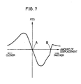
- Fig. 7 is one example of the FES curve showing the relationship between the intensity of the focus error signal thus obtained and the amount of the displacement of the optical disk based on the focal point of the object lens taken as a reference.
- a reference point A represents a case without a focus error.
- a converging point of the reflected beams diffracted toward the photodetector by the diffracting element varies in its position in front of or behind the photodetector in response to fluctuations of the recording medium.
- the value of the focus error signal is reversed from positive to negative in accordance with the amount of the displacement of the recording medium.
- an undesired zero-cross point B appears on the FES curve at a position other than the reference point A.
- an undesired zero-cross point may appear within a dynamic range of focusing control, depending on what arrangement is selected with respect to the optical system. This is related to the fact that the fluctuation of the recording medium causes the shaping prism to have astigmatism.
- the zero-cross point in the FES curve provides a drive target for the object lens in focus servo control, and if a zero-cross point B appears at a position other than the reference point A as described above, the following problems arise.
- focusing control is performed so as to move the object lens from a farther position toward a closer position with respect to the optical disk, for example, in the case of occurrence of an excessive focus error due to an external cause or an initial state of the device, the object lens might be moved to focus on the undesired zero-cross point B. As a result, normal information recording or reproduction might not be performed.
- the optical pickup device of the present invention is characterized in comprising at least the following means:
- the light generation means projects light whose intensity distribution has an elliptical shape with its minor axis parallel to the reference direction, and at least one of the division lines of the diffraction means is set to be parallel to the reference direction.
- the reflected light directed to the diffraction means forms an elliptical bright portion whose major axis is orthogonal to the division line of the diffraction means.
- the function of the diffraction means for diffracting the reflected light so as to converge it on the photodetecting means is little adversely affected. Therefore, in the optical pick-up device in accordance with the present invention, tolerances in the installation position of the diffracting element are alleviated, and the installation work for the diffracting element is simplified.
- the diffracted light can be directed to the photodetecting means. Therefore, a state where the value of the focus error signal shows zero, always indicates the fact that there is no focus error. As a result of this arrangement, accurate focusing control is always performed.
- the light generation means projects light whose major axis of the elliptical shape is parallel to the reference direction
- the intensity distribution shaping means is designed to have the intensity distribution of the elliptical shape condensed with respect to the major axis direction.
- the intensity distribution shaping means does not have an action to further condense the focal distance of the reflected light with respect to the direction of the minor axis.
- the recording medium moves too far away from the position where there is no focus error, for example, as far as several millimeters therefrom, it is avoided that the reflected light forms a bright portion having a line-like shape on the diffraction means.
- the displacement of the recording medium in the order of several millimeters is virtually negligible in actual focusing control. Consequently, since occurrence of an zero-cross point undesirable for the focus error signal for use in the focusing control is avoided, focusing control is always performed accurately.
- the optical pickup device of the present invention makes it possible to always perform a stable recording or reproducing operation.
- Figs. 1, 2 and 3 show one embodiment of the present invention.
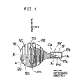
- Fig. 1 is a schematic plan view of a diffracting element and a photodetector of Fig. 2, which are seen in the direction as indicated by arrows I-I.
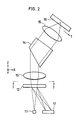
- Fig. 2 is a schematic front view of an optical pickup device.
- Fig. 3 is a schematic plan view of the photodetector.
- Fig. 4 is a schematic plan view showing a diffracting element and a photodetector of another embodiment in accordance with the present invention.
- Figs. 5 and 6 show the other embodiment of the present invention.
- Fig. 5 is a schematic front view of an optical pickup device.
- Fig. 6 is a schematic plan view of a diffracting element and a photodetector of Fig. 5, which are seen in the direction as indicated by arrows VI-VI.
- Fig. 7 is a graph showing the relationship between the amount of displacement of the recording medium based on a focal point of a object lens as a reference and the variation of intensity of a focus error signal.
- X, Y and Z three axis rectangular coordinates are determined using X, Y and Z, as follows.
- the Z-axis is determined to be parallel to an optical axis of light beams projected from a semiconductor laser 11.
- the X-axis is determined to be orthogonal to the Z-axis and further parallel to a hypothetical line extending through a projecting point of the semiconductor laser 11 and the center of a light-receiving face of a photodetector 17, while the Y-axis is determined to be orthogonal to both the X and Z-axes.
- the direction parallel to the X-axis is hereinafter referred to as a reference direction.
- an optical disk 16 is provided with recording tracks preformed thereon, for example, in the form of grooves, and a tangent direction T of a recording track at an illuminating point by the light beams in a recording or reproducing operation is set to be located within an X-Z plane, and further is orthogonal to the optical axis of an object lens 15 as is shown in Fig. 2.
- the semiconductor laser 11 projects light beams whose intensity distribution show an elliptical shape in their cross section (X-Y plane) orthogonal to the optical axis (Z-axis).
- the minor axis of the elliptical shape is parallel to the X-axis, that is, the reference direction, while the major axis is parallel to the Y-axis (Additionally, such intensity distribution of light, related to a cross section orthogonal to the optical axis, is hereinafter referred to simply as the intensity distribution.)
- the light beams having passed through a diffracting element 12 as diffraction means enter to a collimating lens 13 to form a parallel pencil of light beams.
- the intensity distribution of the light beams is shaped from its elliptical shape into a substantially circular shape by a shaping prism 14 as intensity distribution shaping means. That is, the shaping prism 14 diffuses the intensity distribution in its minor axis direction of the elliptical shape.
- the light beams having been thus shaped are converged on the optical disk 16 by the object lens 15.
- any type thereof is selectable among read-only type, direct-read-after-write type, rewritable type, and so on, according to each purpose.
- the light beams reflected from the optical disk 16 (hereinafter, referred to as the reflected beams) trace the light paths from the diffracting element 12 to the optical disk 16 in a reverse order. Therefore, the shaping prism 14 allows the intensity distribution of the reflected beams to change in its shape from the substantially circular shape to the original elliptical shape.
- the reflected beams enter to the diffracting element 12, where they are diffracted so as to be focused on a light-receiving face of the photodetector 17.
- Fig. 1 shows the diffracting element 12, semiconductor laser 11 and photodetector 17 when they are seen from the positive side toward the negative side along the Z-axis as is indicated by arrows I-I in Fig. 2.
- the diffracting element 12 On the diffracting element 12, there is an elliptical bright portion formed by the reflected beams directed thereto.
- the diffracting element 12 is divided into two regions 12a and 12b by a division line l1 parallel to the X-axis.
- the minor axis of the elliptical bright portion is parallel to the division line l1, that is, the reference direction.
- the pitch of grating 12c formed in the region 12a is set to be greater than that of grating 12d formed in the region 12b.
- an angle of diffraction with respect to a reflected beam Pb directed to the region 12b is greater than an angle of diffraction with respect to another reflected beam Pa directed to the region 12a.
- Fig. 3 shows a plan view of the photodetector 17.
- the photodetector 17 is divided into three photodetecting regions 17a, 17b and 17c by a division line l2 parallel to the Y-axis and a division line l3 which is extended from a middle point of the division line l2 in the positive direction of the X-axis.
- the reflected beam Pa diffracted by the region 12a of the diffracting element 12 is focused on a substantial center of the photodetecting region 17a to form a light spot Pa′.
- the reflected beam Pb diffracted by the region 12b is focused on a substantial middle point of the division line l3 separating the photodetecting regions 17b and 17c to form a light spot Pb′.
- detection signals released from the photodetecting regions 17a, 17b and 17c are represented respectively as Sa, Sb and Sc.
- the object lens 15 is controlled through a focus driving system and a radial driving system (not shown) so that each of the values of FES and RES may equal "0".
- the optical pickup device which is arranged so that the minor axis of an elliptical bright portion formed on the diffracting element 12 by reflected beams may coincide with the division line l1, as described above, has the following advantages. For example, in the case where the optical disk 16 is fluctuated to move away from a focal point of the object lens 15, there is formed a line-like bright portion on the diffracting element 12 due to the astigmatism of the shaping prism 14 (shown by a heavy line P in Fig. 1).
- the line-like bright portion P is formed so as to be orthogonal to the division line l1
- the division line l1 slightly tilts with respect to the X-axis, or slightly deviates from the optical axis, those factors have little adverse effects on the requirement that the bright portion P should be evenly allotted onto the regions 12a and 12b. Therefore, even if a bright portion P having a line-like shape is formed on the diffracting element 12, an appropriate focus error signal FES can be obtained.
- a light spot Pb′ is first formed either on the photodetecting region 17b or on 17c, and then formed on the other region in an inverted shape as the optical disk 16 further moves away from the focal point of the object lens 15.
- the focus error signal FES is little adversely affected by the fluctuation of the optical disk 16.
- a zero-cross point of the FES curve (which shows the variation of intensity of the focus error signal FES with the amount of displacement of the optical disk 16) appears only in a state where the optical disk 16 is positioned at the focal point of the object lens 15 (which state is hereinafter referred to as the just-in-focus state), thereby permitting focus error control to be appropriately performed.
- the just-in-focus state which state is hereinafter referred to as the just-in-focus state
- a diffracting element 18 is divided into two regions 18a and 18b by a division line l4 parallel to the X-axis.
- gratings 18c and 18d formed in the respective regions 18a and 18b are not orthogonal to the division line l4 but slightly tilted with respect thereto.
- Each of the gratings 18c and 18d makes the same obtuse angle ⁇ with respect to the X-axis in the positive direction.
- the minor axis of an elliptical bright portion formed on the diffracting element 18 is set to be parallel to the X-axis, that is, the reference direction.
- a photodetector 19 is divided into four photodetecting regions 19a, 19b, 19c and 19d by three division lines l5, l6 and l7, each of which is substantially parallel to the division line l4 (e.g., see pages 162 and 163 together with Fig. 6 of "CD Optical Pickup using a Computer Generated Holographic Optical element" in Optical Storage and Scanning Technology, TonyWilson, Editor, Proc.
- the installation position of the photodetector 19 is determined as follows:
- the arrangement is the same as that of the first embodiment except the diffracting element 18 and the photodetector 19.
- the semiconductor laser 11 of Fig. 5 projects light beams whose intensity distribution has an elliptical shape with its major axis parallel to the X-axis, that is, the reference direction, and its minor axis parallel to the Y-axis, having a reversed disposition to the above two embodiments.
- a shaping prism 20 is designed to cause the intensity distribution of the elliptical shape to be condensed with respect to the major axis direction, that is, the reference direction. With the arrangement, the intensity distribution of the light beams is changed in its shape from the elliptical one to a substantially circular one.
- the intensity distribution of the reflected beams is changed from its substantially circular shape to a substantially elliptical shape. Consequently, as shown in Fig. 6, a bright portion which is formed by the reflected beams illuminating the diffracting element 12 in the just-in-focus state, has an elliptical shape whose major axis is parallel to the X-axis, that is, the reference direction, and coincides with the division line l1.
- the diffracting element 12 and the photodetector 17 have the same configurations as those of the first embodiment. Therefore, a reflected beam Pa diffracted by the region 12a of the diffracting element 12 in the just-in-focus state forms a light spot Pa′ in a substantial center of the photodetector 17a. On the other hand, a reflected beam Pb diffracted by the region 12b forms a light spot Pb′ at a substantial middle point of the division line l3.
- the shaping prism 20 of the third embodiment has a shaping function on the intensity distribution of the light beams from the semiconductor laser 11 and the reflected beams from the optical disk 16 in the direction of the major axis, but has no effects on the intensity distribution in the direction of the minor axis. Therefore, in the case where the optical disk 16 is fluctuated to move away from a focal point of the object lens 15, the shaping prism 20 has no bearing on the focal distances of the reflected beams with respect to the minor-axis direction, although it has bearing on that the focal distances are extended with respect to the major-axis direction.
- the reflected beams form a substantially line-like bright portion such as shown by a heavy line P on the diffracting element 12 only in the case where the optical disk 16 is fluctuated to move away from the focal point to a great extent.
- the displacement of the optical disk 16 reaches, for example, substantial several millimeters, and becomes too great to be included within a control range of focus errors.
- an optical pickup device of the third embodiment provides stable focusing control, and makes it possible to perform a preferable recording or reproducing operation.
- the third embodiment shows the arrangement wherein the major axis of the elliptical bright portion formed on the diffracting element 12 coincides with the division line l1; yet, another arrangement may be adopted, wherein the minor axis thereof coincides with the division line l1. In either case, it is important to adopt the arrangement wherein the shaping prism 20 functions to shape the intensity distribution with respect to the major axis direction.
- the optical pickup device of the present invention includes diffraction means whose diffraction face is divided by division lines parallel to the reference direction and photodetecting means whose light-receiving face is divided by division lines substantially parallel to the reference direction.
- the reflected beams from the recording medium form on the diffraction face an elliptical bright portion whose major axis is orthogonal to the reference direction.
- the optical pickup device of the present invention may include intensity distribution shaping means which condenses the intensity distribution of light whose intensity distribution has an substantially elliptical shape, with respect to the direction of the major axis.
- intensity distribution shaping means which condenses the intensity distribution of light whose intensity distribution has an substantially elliptical shape, with respect to the direction of the major axis.
- reflected beams from the recording medium are arranged to form on the diffraction face an elliptical bright portion with its minor axis orthogonal to the reference direction.
Landscapes
- Physics & Mathematics (AREA)
- Optics & Photonics (AREA)
- General Physics & Mathematics (AREA)
- Optical Recording Or Reproduction (AREA)
- Optical Head (AREA)
- Automatic Focus Adjustment (AREA)
Applications Claiming Priority (2)
| Application Number | Priority Date | Filing Date | Title |
|---|---|---|---|
| JP2105937A JPH0721869B2 (ja) | 1990-04-20 | 1990-04-20 | 光ピックアップ装置 |
| JP105937/90 | 1990-04-20 |
Publications (3)
| Publication Number | Publication Date |
|---|---|
| EP0453323A2 true EP0453323A2 (de) | 1991-10-23 |
| EP0453323A3 EP0453323A3 (en) | 1992-06-03 |
| EP0453323B1 EP0453323B1 (de) | 1995-12-13 |
Family
ID=14420765
Family Applications (1)
| Application Number | Title | Priority Date | Filing Date |
|---|---|---|---|
| EP91303579A Expired - Lifetime EP0453323B1 (de) | 1990-04-20 | 1991-04-22 | Optische Abtastvorrichtung |
Country Status (6)
| Country | Link |
|---|---|
| US (1) | US5173890A (de) |
| EP (1) | EP0453323B1 (de) |
| JP (1) | JPH0721869B2 (de) |
| KR (1) | KR970008230B1 (de) |
| CA (1) | CA2040787C (de) |
| DE (1) | DE69115336T2 (de) |
Cited By (2)
| Publication number | Priority date | Publication date | Assignee | Title |
|---|---|---|---|---|
| EP0459764B1 (de) * | 1990-05-29 | 1996-12-11 | Sharp Kabushiki Kaisha | Anordnung eines optischen Kopfes |
| CN110634372A (zh) * | 2019-09-29 | 2019-12-31 | 中国科学院长春光学精密机械与物理研究所 | 一种光学系统装调策略验证系统 |
Families Citing this family (6)
| Publication number | Priority date | Publication date | Assignee | Title |
|---|---|---|---|---|
| JP3112735B2 (ja) * | 1992-02-28 | 2000-11-27 | パイオニア株式会社 | 光ピックアップ装置 |
| US5453962A (en) * | 1992-08-20 | 1995-09-26 | Mitsubishi Denki Kabushiki Kaisha | Focus error detecting device |
| JP3058386B2 (ja) * | 1992-09-10 | 2000-07-04 | 株式会社東芝 | 光学ヘッド装置及びこれを用いた光ディスク装置 |
| US5615200A (en) * | 1992-09-10 | 1997-03-25 | Kabushiki Kaisha Toshiba | Light beam shaping device to change an anisotropic beam to an isotropic beam for reducing the size of an optical head |
| JP3645319B2 (ja) * | 1995-07-31 | 2005-05-11 | 株式会社東芝 | 情報処理装置 |
| JPH1064104A (ja) * | 1996-08-21 | 1998-03-06 | Pioneer Electron Corp | 非点収差フォーカスエラー信号生成方法及び光ピックアップ装置 |
Family Cites Families (11)
| Publication number | Priority date | Publication date | Assignee | Title |
|---|---|---|---|---|
| JPS62248139A (ja) * | 1986-04-21 | 1987-10-29 | Sharp Corp | 焦点検出装置 |
| US4789977A (en) * | 1986-11-06 | 1988-12-06 | Laser Magnetic Storage International Company | Optical data recording device |
| NL8701749A (nl) * | 1987-07-24 | 1989-02-16 | Philips Nv | Inrichting voor het met optische straling aftasten van een informatievlak. |
| JPH01151022A (ja) * | 1987-12-09 | 1989-06-13 | Sharp Corp | 光ピックアップ装置 |
| JPH01258240A (ja) * | 1988-04-07 | 1989-10-16 | Sharp Corp | 光学的情報読取り装置 |
| JPH0770065B2 (ja) * | 1988-04-20 | 1995-07-31 | シャープ株式会社 | 光ピックアップ装置 |
| JPH01311428A (ja) * | 1988-06-09 | 1989-12-15 | Matsushita Electric Ind Co Ltd | 光ヘッド装置及びこれを用いた光情報装置 |
| US5066138A (en) * | 1988-06-16 | 1991-11-19 | Mitsubishi Denki Kabushiki Kaisha | Optical head apparatus |
| US4983017A (en) * | 1988-08-02 | 1991-01-08 | Sharp Kabushiki Kaisha | Optical head device for reading information stored in a recording medium |
| JPH0758559B2 (ja) * | 1988-09-02 | 1995-06-21 | シャープ株式会社 | 光ピックアップ装置 |
| JP2975395B2 (ja) * | 1990-05-15 | 1999-11-10 | シャープ株式会社 | 光ピックアップ装置 |
-
1990
- 1990-04-20 JP JP2105937A patent/JPH0721869B2/ja not_active Expired - Lifetime
-
1991
- 1991-04-17 KR KR1019910006168A patent/KR970008230B1/ko not_active Expired - Fee Related
- 1991-04-18 CA CA002040787A patent/CA2040787C/en not_active Expired - Fee Related
- 1991-04-18 US US07/687,478 patent/US5173890A/en not_active Expired - Lifetime
- 1991-04-22 EP EP91303579A patent/EP0453323B1/de not_active Expired - Lifetime
- 1991-04-22 DE DE69115336T patent/DE69115336T2/de not_active Expired - Lifetime
Cited By (2)
| Publication number | Priority date | Publication date | Assignee | Title |
|---|---|---|---|---|
| EP0459764B1 (de) * | 1990-05-29 | 1996-12-11 | Sharp Kabushiki Kaisha | Anordnung eines optischen Kopfes |
| CN110634372A (zh) * | 2019-09-29 | 2019-12-31 | 中国科学院长春光学精密机械与物理研究所 | 一种光学系统装调策略验证系统 |
Also Published As
| Publication number | Publication date |
|---|---|
| US5173890A (en) | 1992-12-22 |
| CA2040787A1 (en) | 1991-10-21 |
| JPH0721869B2 (ja) | 1995-03-08 |
| KR910018996A (ko) | 1991-11-30 |
| DE69115336T2 (de) | 1996-06-05 |
| CA2040787C (en) | 1993-10-12 |
| EP0453323A3 (en) | 1992-06-03 |
| KR970008230B1 (ko) | 1997-05-22 |
| DE69115336D1 (de) | 1996-01-25 |
| EP0453323B1 (de) | 1995-12-13 |
| JPH043336A (ja) | 1992-01-08 |
Similar Documents
| Publication | Publication Date | Title |
|---|---|---|
| US4731772A (en) | Optical head using hologram lens for both beam splitting and focus error detection functions | |
| EP0305169A2 (de) | Optische Abtastvorrichtung und optische Gitteranordnung dazu | |
| US4767921A (en) | Optical pickup device wherein the astigmatic converged beam spot is aligned along the dividing lines of the four-division photo-detector | |
| US5608695A (en) | Optical pick-up apparatus with tracking error detection by detection of amount of light in fan field | |
| US4716283A (en) | Optical head for focusing a light beam on an optical disk | |
| US7072270B2 (en) | Method and device for detecting optical data and reading-writing apparatus for optical data | |
| US5173890A (en) | Optical pickup device including diffraction grating | |
| US5737295A (en) | Dual-focus optical pickup for different thicknesses of recording medium | |
| US7064900B2 (en) | Optical pickup device and optical disk device and optical device and composite optical element | |
| EP0457573B1 (de) | Optischer Kopf | |
| CA2043387C (en) | Optical head device | |
| US5202869A (en) | Optical head device including diffraction grating | |
| EP0311463A2 (de) | Optisches Informationswiedergabegerät | |
| US5144131A (en) | Device for optically scanning an information plane detecting border portions of light beam | |
| EP0814466A2 (de) | Optischer Kopf | |
| US20050162995A1 (en) | Optical pickup device, optical disk drive, optical device and composite optical element | |
| EP0336737A2 (de) | Optisches Informationswiedergabegerät | |
| US5691970A (en) | Optical pickup for high-density recording/reproducing | |
| JPH07105059B2 (ja) | 光学式ピックアップ装置 | |
| US5317557A (en) | Optical head for recording and reproducing information on and/or from optical record medium | |
| JP3115761B2 (ja) | 光学ヘッド | |
| JP2886353B2 (ja) | 光情報記録再生装置 | |
| JPH0554411A (ja) | 光学式情報記録再生装置 | |
| US6538976B1 (en) | Optical spot generation device for recording medium | |
| EP0628955B1 (de) | Optischer Kopf |
Legal Events
| Date | Code | Title | Description |
|---|---|---|---|
| PUAI | Public reference made under article 153(3) epc to a published international application that has entered the european phase |
Free format text: ORIGINAL CODE: 0009012 |
|
| AK | Designated contracting states |
Kind code of ref document: A2 Designated state(s): DE FR GB IT NL |
|
| PUAL | Search report despatched |
Free format text: ORIGINAL CODE: 0009013 |
|
| AK | Designated contracting states |
Kind code of ref document: A3 Designated state(s): DE FR GB IT NL |
|
| 17P | Request for examination filed |
Effective date: 19921110 |
|
| 17Q | First examination report despatched |
Effective date: 19940816 |
|
| GRAA | (expected) grant |
Free format text: ORIGINAL CODE: 0009210 |
|
| AK | Designated contracting states |
Kind code of ref document: B1 Designated state(s): DE FR GB IT NL |
|
| REF | Corresponds to: |
Ref document number: 69115336 Country of ref document: DE Date of ref document: 19960125 |
|
| ITF | It: translation for a ep patent filed | ||
| ET | Fr: translation filed | ||
| PLBE | No opposition filed within time limit |
Free format text: ORIGINAL CODE: 0009261 |
|
| STAA | Information on the status of an ep patent application or granted ep patent |
Free format text: STATUS: NO OPPOSITION FILED WITHIN TIME LIMIT |
|
| 26N | No opposition filed | ||
| REG | Reference to a national code |
Ref country code: GB Ref legal event code: IF02 |
|
| PGFP | Annual fee paid to national office [announced via postgrant information from national office to epo] |
Ref country code: NL Payment date: 20050403 Year of fee payment: 15 |
|
| PGFP | Annual fee paid to national office [announced via postgrant information from national office to epo] |
Ref country code: GB Payment date: 20050420 Year of fee payment: 15 |
|
| PG25 | Lapsed in a contracting state [announced via postgrant information from national office to epo] |
Ref country code: GB Free format text: LAPSE BECAUSE OF NON-PAYMENT OF DUE FEES Effective date: 20060422 |
|
| PGFP | Annual fee paid to national office [announced via postgrant information from national office to epo] |
Ref country code: IT Payment date: 20060430 Year of fee payment: 16 |
|
| PG25 | Lapsed in a contracting state [announced via postgrant information from national office to epo] |
Ref country code: NL Free format text: LAPSE BECAUSE OF NON-PAYMENT OF DUE FEES Effective date: 20061101 |
|
| GBPC | Gb: european patent ceased through non-payment of renewal fee |
Effective date: 20060422 |
|
| NLV4 | Nl: lapsed or anulled due to non-payment of the annual fee |
Effective date: 20061101 |
|
| PG25 | Lapsed in a contracting state [announced via postgrant information from national office to epo] |
Ref country code: IT Free format text: LAPSE BECAUSE OF NON-PAYMENT OF DUE FEES Effective date: 20070422 |
|
| PGFP | Annual fee paid to national office [announced via postgrant information from national office to epo] |
Ref country code: FR Payment date: 20100521 Year of fee payment: 20 |
|
| PGFP | Annual fee paid to national office [announced via postgrant information from national office to epo] |
Ref country code: DE Payment date: 20100430 Year of fee payment: 20 |
|
| REG | Reference to a national code |
Ref country code: DE Ref legal event code: R071 Ref document number: 69115336 Country of ref document: DE |
|
| PG25 | Lapsed in a contracting state [announced via postgrant information from national office to epo] |
Ref country code: DE Free format text: LAPSE BECAUSE OF EXPIRATION OF PROTECTION Effective date: 20110422 |