EP0453570A1 - Procede de preparation de programmes de commande numerique pour unite de commande numerique interactive ou appareil de programmation automatique - Google Patents
Procede de preparation de programmes de commande numerique pour unite de commande numerique interactive ou appareil de programmation automatique Download PDFInfo
- Publication number
- EP0453570A1 EP0453570A1 EP90915814A EP90915814A EP0453570A1 EP 0453570 A1 EP0453570 A1 EP 0453570A1 EP 90915814 A EP90915814 A EP 90915814A EP 90915814 A EP90915814 A EP 90915814A EP 0453570 A1 EP0453570 A1 EP 0453570A1
- Authority
- EP
- European Patent Office
- Prior art keywords
- machining
- primary
- program
- shape
- secondary machining
- Prior art date
- Legal status (The legal status is an assumption and is not a legal conclusion. Google has not performed a legal analysis and makes no representation as to the accuracy of the status listed.)
- Withdrawn
Links
Images




Classifications
-
- G—PHYSICS
- G05—CONTROLLING; REGULATING
- G05B—CONTROL OR REGULATING SYSTEMS IN GENERAL; FUNCTIONAL ELEMENTS OF SUCH SYSTEMS; MONITORING OR TESTING ARRANGEMENTS FOR SUCH SYSTEMS OR ELEMENTS
- G05B19/00—Program-control systems
- G05B19/02—Program-control systems electric
- G05B19/18—Numerical control [NC], i.e. automatically operating machines, in particular machine tools, e.g. in a manufacturing environment, so as to execute positioning, movement or co-ordinated operations by means of program data in numerical form
- G05B19/4093—Numerical control [NC], i.e. automatically operating machines, in particular machine tools, e.g. in a manufacturing environment, so as to execute positioning, movement or co-ordinated operations by means of program data in numerical form characterised by part programming, e.g. entry of geometrical information as taken from a technical drawing, combining this with machining and material information to obtain control information, named part program, for the NC machine
- G05B19/40931—Numerical control [NC], i.e. automatically operating machines, in particular machine tools, e.g. in a manufacturing environment, so as to execute positioning, movement or co-ordinated operations by means of program data in numerical form characterised by part programming, e.g. entry of geometrical information as taken from a technical drawing, combining this with machining and material information to obtain control information, named part program, for the NC machine concerning programming of geometry
- G05B19/40932—Shape input
-
- G—PHYSICS
- G05—CONTROLLING; REGULATING
- G05B—CONTROL OR REGULATING SYSTEMS IN GENERAL; FUNCTIONAL ELEMENTS OF SUCH SYSTEMS; MONITORING OR TESTING ARRANGEMENTS FOR SUCH SYSTEMS OR ELEMENTS
- G05B2219/00—Program-control systems
- G05B2219/30—Nc systems
- G05B2219/36—Nc in input of data, input key till input tape
- G05B2219/36338—Create program for parallel, simultaneous operated slides, timing
-
- G—PHYSICS
- G05—CONTROLLING; REGULATING
- G05B—CONTROL OR REGULATING SYSTEMS IN GENERAL; FUNCTIONAL ELEMENTS OF SUCH SYSTEMS; MONITORING OR TESTING ARRANGEMENTS FOR SUCH SYSTEMS OR ELEMENTS
- G05B2219/00—Program-control systems
- G05B2219/30—Nc systems
- G05B2219/36—Nc in input of data, input key till input tape
- G05B2219/36339—Time necessary for one slide equals time for second slide
-
- G—PHYSICS
- G05—CONTROLLING; REGULATING
- G05B—CONTROL OR REGULATING SYSTEMS IN GENERAL; FUNCTIONAL ELEMENTS OF SUCH SYSTEMS; MONITORING OR TESTING ARRANGEMENTS FOR SUCH SYSTEMS OR ELEMENTS
- G05B2219/00—Program-control systems
- G05B2219/30—Nc systems
- G05B2219/45—Nc applications
- G05B2219/45125—Four axis, spindle lathe
-
- Y—GENERAL TAGGING OF NEW TECHNOLOGICAL DEVELOPMENTS; GENERAL TAGGING OF CROSS-SECTIONAL TECHNOLOGIES SPANNING OVER SEVERAL SECTIONS OF THE IPC; TECHNICAL SUBJECTS COVERED BY FORMER USPC CROSS-REFERENCE ART COLLECTIONS [XRACs] AND DIGESTS
- Y02—TECHNOLOGIES OR APPLICATIONS FOR MITIGATION OR ADAPTATION AGAINST CLIMATE CHANGE
- Y02P—CLIMATE CHANGE MITIGATION TECHNOLOGIES IN THE PRODUCTION OR PROCESSING OF GOODS
- Y02P90/00—Enabling technologies with a potential contribution to greenhouse gas [GHG] emissions mitigation
- Y02P90/02—Total factory control, e.g. smart factories, flexible manufacturing systems [FMS] or integrated manufacturing systems [IMS]
Definitions
- the present invention relates to an interactive numerical control device or an automatic programming device, and more particularly, to a method of preparing an NC program for an interactive numerical control device or an automatic programming device used for preparing an NC program for a four-axis lathe with two spindles and two turrets.
- An interactive numerical control device or an automatic programming device is widely used for the control of various machine tools, since an NC program can be easily prepared even if an operator is not familiar with the language codes or NC tape formats, etc. of an automatic programming.
- a four-axis lathe with two spindles and two turrets has been used as a CNC lathe having a plurality of heads, to improve the machining efficiency.
- This type of four-axis lathe carries out a primary machining with one head, and then carries out a secondary machining (sometimes referred to as back machining) with the other head.
- Figure 6 is a diagram for explaining the outline of a machining with a four-axis lathe with two spindles and two turrets.
- a workpiece 42a held by a chuck 41a is machined to a desired contour with a tool 44a mounted on a turret 43a.
- This machining at the first head is referred to as a primary machining.
- the workpiece 42a is moved from the chuck 41a to a chuck 41b, and a workpiece 42b caught by the chuck 41b is machined to a desired contour with a tool 44b mounted on a turret 43b.
- This machining at the second head is referred to as a secondary machining.
- the time required for the primary machining and the time required for the secondary machining are made the same. Namely, the overall machining time can be reduced and machining efficiency can be improved by making the machining time for the primary and the secondary machining the same when a workpiece is machined while continuously changing the position in which it is held.
- a zone for the primary machining (primary machining zone) and a zone for the secondary machining (secondary machining zone) must be set such that machining times for the primary and the secondary machining become the same.
- the interactive numerical control device or the automatic programming device employs a method of inputting a part shape by inputting shape components using symbolic keys. This is used to prepare a machining program by inputting a part shape using symbolic keys by which shape components such as a horizontal line, vertical line, oblique line, partial arc, etc. can be input.
- This method has an advantage in that an NC program can be easily and efficiently prepared because a shape of a part can be easily input.
- the primary machining zone and the secondary machining zone must be set, and at this time, a problem arises in that the machining zones cannot be set such that the machining times for the primary and the secondary machining become the same since a part shape is composed of several shape components.
- Figure 6 is a diagram showing a material shape, and a part shape input through the symbolic keys. In this figure, only a display screen 1 is shown and the input keys, etc. are omitted.
- the display screen 1 shows a material shape 2 defined by a rectangle and a part shape 3 surrounded by a line segment (shape components) from a point A to a point J, within this material shape 2.
- the shaded section in the figure is a machining cutting zone 4 to be cut with a tool.
- X refers to the X-axis direction and Z to the Z-axis direction of a four-axis lathe.
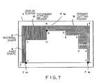
- Figures 7 and 8 are diagrams showing the display at display screens when the cutting zones of the primary and the secondary machining are set. Namely, after the material shape 2 and the part shape 3 are defined as in Fig. 6, the primary machining zone is set, and therefore, first a cursor 7a is moved to the point A on the part shape 3, and a starting point for a splitting is set by pushing a right arrow key. Next, a cursor 7b is moved to a point G, and an end point of a splitting is set by pushing an upper arrow key. By this operation, a zone surrounded by points A - B - C - D - E - F - G - Q - X (lateral line section) is set as a primary machining cutting zone 5.
- a cursor 7c is moved to the point J, and a zone surrounded by points Q - G - H - I - J - Z (longitudinal line section) is set as a secondary machining cutting zone 6, by pushing a left arrow key.
- Figure 8 shows a case where in the point F is set as a splitting point by the same operation, and the primary machining cutting zone 5 is surrounded by the points A - B - C - D - E - F - Q - X (lateral line section) and the secondary machining cutting zone 6 is surrounded by the points Q - F - G - H - I - J - Z (longitudinal line section).
- the primary machining cutting zone 5 is made about 15% larger than the secondary machining cutting zone 6, and in the case of the splitting as shown in Fig. 8, the primary machining cutting zone 5 is made about 20% smaller than the secondary machining cutting zone 6.
- the present invention has been made in view of the aforesaid drawbacks, and an object of the present invention is to provide a method of preparing an NC program for an interactive numerical control device or an automatic programming device by which the times required for a primary machining and a secondary machining can be made the same.
- the method of preparing an NC program for an interactive numerical control device or an automatic programming device being characterized in that a splitting point between the primary machining and the secondary machining is determined based on data of the material shape and the part shape consisting of shape components input by the interactive numerical control device or the automatic programming device, and the NC program for the primary machining and the secondary machining is prepared such that times required for the primary machining and the secondary machining are almost the same, taking the above splitting point as the basis.
- the material shape and the part shape are input to the interactive numerical control device or the automatic programming device using symbolic keys representing the shape components, and the entire machining zone to be machined in the primary machining and the secondary machining can be calculated from data of these material and part shapes. Namely, when an area of the part shape is subtracted from an area of the material shape, the remaining section is the area of the entire machining zone. Also, the length of the shape components, etc. constituting the part shape can be calculated based on the data of the material and the part shapes, and therefore, the splitting point between the primary machining and the secondary machining is determined by the area of the entire machining zone, the area of the part shape or the length, etc.
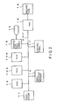
- FIG. 2 is a schematic diagram of a constitution of an interactive numerical control device as an embodiment of the present invention, wherein a processor 11 controls the operation of the whole interactive numerical control device according to a system program stored in a ROM 12, which is an EPROM or EEPROM.
- a ROM 12 which is an EPROM or EEPROM.
- a DRAM or the like is used for a RAM 13, and various data or input/output signals are stored therein.
- a CMOS backed up by a battery is used for a nonvolatile memory 14, and parameters, pitch error correction amounts, tool correction amounts, etc., which must be held after the power supply is cut off, are stored therein.
- a graphic control circuit 15 converts a digital signal to a display a signal and supplies it to a display unit 16.
- a CRT or a liquid crystal display unit is used for the display unit 16, and a material shape, part shape, machining definition screen, and positional indications of respective axes, parameters, etc. are displayed thereat.
- a control panel 17 is constituted by a keyboard, etc. and is used for inputting various data or for an operation of a machine tool 19.
- a PMC (programmable machine controller) 18 receives an output signal via a bus 20, processes the output signal by a sequence program, and controls the machine tool 19 accordingly, and further, receives an input signal from a machine, processes the input signal by a sequence program, and transfers the processed input signal to the processor 11 via the bus 20.
- bus 20 Those components are interconnected by the bus 20.
- a multiprocessor system components such as an axis control circuit, servo amplifier, servo motor, spindle amplifier, spindle motor, etc. have been omitted in Fig. 2, and further, a plurality of processors may be used to thus constitute a multiprocessor system.
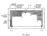
- Figure 3 is a diagram showing an example of a display screen of an interactive numerical control device as an embodiment of the present invention.
- Fig. 3 the same symbols are given to the same components shown in Fig. 7, and thus an explanation thereof will be omitted.
- a splitting point can be set at an arbitrary point on the shape components.
- the splitting point could be set only at the intersections A, B... J of the shape components in the conventional art, but in this embodiment, a cursor can be moved to an arbitrary point P between the points F and G of the shape components, and thus a point such that areas of a primary machining cutting zone 5 and a secondary machining cutting zone 6 are made equal to each other can be set as the splitting point. If a cursor can be moved to an arbitrary point on the entire shape components, the positions of all those points must be stored, and therefore in this embodiment, the cursor is arbitrarily moved only on the shape components at which the splitting point exists.
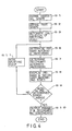
- Figure 1 shows a flow chart of the process of this embodiment.
- numerical values following the letter S show the number of the Step.
- the operator determines whether or not the machining times are appropriate by checking the displayed machining times, but whether or not the machining times are appropriate may be determined in the interactive numerical control device or the automatic programming device.
- FIG. 4 is another flow chart showing the operation of this embodiment.
- Fig. 4 as the same symbols are given to the same Steps of Fig. 3, an explanation thereof will be omitted.
- the determination is made of whether or not the difference between the time required for the primary machining and the time required for the secondary machining is within a predetermined error range of ! ⁇ 5%, but it can be determined whether or not the difference between the time required for the primary machining and the time required for the secondary machining is within a predetermined time (e.g., one to three minutes), and such an error range or time range is set as a parameter.
- a predetermined time e.g., one to three minutes
- the splitting point is changed and moved by a predetermined amount so that the machining zone of the machining needing a longer machining time is made smaller.
- a predetermined amount of change and movement is determined according to the size of the difference between the time required for the primary machining and the time required for the secondary machining obtained in S9. For example, when the machining time for the primary machining is longer than that of the secondary machining, by about 10%, the change and movement is made such that the area of the primary machining cutting zone 5 is made smaller by about 10%. Accordingly, the difference between the time required for the primary machining and the time required for the secondary machining is brought within the above error range or time range.
- the splitting point is automatically calculated so that the machining time is the same for the primary and the secondary machining, and the NC sentence is output based on the calculated splitting point.
- the material shape and the part shape are both observed as cross sectional areas at the display screen, the entire machining area to be machined is calculated from the data of the material shape and the part shape, and a point is made the splitting point such that both of these areas become almost equal when the area of the entire machining zone is split with a line segment perpendicular to the Z-axis of the four-axis lathe.
- splitting point also can be calculated by the following method.
- a point such that both areas are equal to each other when the area of the part shape 3 is split with the line segment perpendicular to the Z-axis of the four-axis lathe can be made the splitting point.
- a point such that the lengths of the shape components A - B - C - D - E - F - G - H - I - J constituting the part shape 3 are equal to each other can be made the splitting point.
- the middle point of the shape component F - G having a distance in the radial X direction that is the longest among the shape components A - B - C - D - E - F - G - H - I - J constituting the part shape 3, can be made the splitting point.
- a point at about half the length in the Z-axis direction of the material shape 2 or the part shape 3 can be made the splitting point.
- a number of points can be set as the splitting point, and any one of those splitting points can be set as a parameter, or after calculating the machining time for all of those splitting points, a point such that the time required for the primary machining and the time required for the secondary machining are substantially the same can be made the splitting point.
- a primary machining program and a secondary machining program of an NC program for a four-axis lathe having two spindles and two turrets are produced at the same time, and the primary machining time and the secondary machining time can be made the same, to thereby significantly improve the machining efficiency.
Landscapes
- Physics & Mathematics (AREA)
- Engineering & Computer Science (AREA)
- Geometry (AREA)
- Human Computer Interaction (AREA)
- Manufacturing & Machinery (AREA)
- General Physics & Mathematics (AREA)
- Automation & Control Theory (AREA)
- Numerical Control (AREA)
Abstract
Procédé de préparation d'un programme d'unité de commande numérique interactive pour un tour à deux broches, deux tourelles revolver et quatre axes en fonction des formes d'une pièce à usiner ainsi produite, subissant un usinage principal et un usinage secondaire. Le point entre les processus d'usinage principal et secondaire est déterminé (S1, S2, S3) en fonction des données relatives aux éléments constitutifs de la forme de la pièce à usiner introduits. Ce point dans le programme de commande numérique est sélectionné (S4 - S10) de sorte que le temps nécessaire pour l'usinage principal et l'usinage secondaire soit sensiblement égal. On peut ainsi préparer un programme très efficient pour la commande numérique d'un tour à quatre axes.
Applications Claiming Priority (2)
| Application Number | Priority Date | Filing Date | Title |
|---|---|---|---|
| JP1295277A JPH03156506A (ja) | 1989-11-14 | 1989-11-14 | 対話型数値制御装置又は自動プログラミング装置のncプログラム作成方法 |
| JP295277/89 | 1989-11-14 |
Publications (1)
| Publication Number | Publication Date |
|---|---|
| EP0453570A1 true EP0453570A1 (fr) | 1991-10-30 |
Family
ID=17818520
Family Applications (1)
| Application Number | Title | Priority Date | Filing Date |
|---|---|---|---|
| EP90915814A Withdrawn EP0453570A1 (fr) | 1989-11-14 | 1990-10-24 | Procede de preparation de programmes de commande numerique pour unite de commande numerique interactive ou appareil de programmation automatique |
Country Status (3)
| Country | Link |
|---|---|
| EP (1) | EP0453570A1 (fr) |
| JP (1) | JPH03156506A (fr) |
| WO (1) | WO1991007707A1 (fr) |
Cited By (2)
| Publication number | Priority date | Publication date | Assignee | Title |
|---|---|---|---|---|
| WO2005002792A1 (fr) | 2003-07-04 | 2005-01-13 | Mitsubishi Denki Kabushiki Kaisha | Procédé et dispositif de programmation automatique |
| EP1677169A3 (fr) * | 2004-12-28 | 2009-09-30 | Yamazaki Mazak Corporation | Méthode et dispositif pour la division automatique d'un procédé d'usinage dans un dispositif de programmation automatique |
Families Citing this family (1)
| Publication number | Priority date | Publication date | Assignee | Title |
|---|---|---|---|---|
| JPH05177504A (ja) * | 1991-12-27 | 1993-07-20 | Mori Seiki Co Ltd | Nc文作成装置 |
Family Cites Families (2)
| Publication number | Priority date | Publication date | Assignee | Title |
|---|---|---|---|---|
| JPS62251044A (ja) * | 1986-04-23 | 1987-10-31 | Fanuc Ltd | 4軸旋盤のncプログラム作成方法 |
| JP2673960B2 (ja) * | 1988-08-30 | 1997-11-05 | ヤマザキマザック株式会社 | 2スピンドル工作機械における加工制御方法及び制御装置 |
-
1989
- 1989-11-14 JP JP1295277A patent/JPH03156506A/ja active Pending
-
1990
- 1990-10-24 EP EP90915814A patent/EP0453570A1/fr not_active Withdrawn
- 1990-10-24 WO PCT/JP1990/001376 patent/WO1991007707A1/fr not_active Ceased
Non-Patent Citations (1)
| Title |
|---|
| See references of WO9107707A1 * |
Cited By (4)
| Publication number | Priority date | Publication date | Assignee | Title |
|---|---|---|---|---|
| WO2005002792A1 (fr) | 2003-07-04 | 2005-01-13 | Mitsubishi Denki Kabushiki Kaisha | Procédé et dispositif de programmation automatique |
| EP1642675A4 (fr) * | 2003-07-04 | 2009-05-13 | Mitsubishi Electric Corp | Procede et dispositif de programmation automatique |
| US7620473B2 (en) | 2003-07-04 | 2009-11-17 | Mitsubishi Denki Kabushiki Kaisha | Automatic programming method and automatic programming device for controlling numeric control unit based on the division of the machining area |
| EP1677169A3 (fr) * | 2004-12-28 | 2009-09-30 | Yamazaki Mazak Corporation | Méthode et dispositif pour la division automatique d'un procédé d'usinage dans un dispositif de programmation automatique |
Also Published As
| Publication number | Publication date |
|---|---|
| JPH03156506A (ja) | 1991-07-04 |
| WO1991007707A1 (fr) | 1991-05-30 |
Similar Documents
| Publication | Publication Date | Title |
|---|---|---|
| KR930007256B1 (ko) | 4축선반용 nc프로그램편집 방법 | |
| EP0265525B1 (fr) | Procede de preparation d'un programme de commande numerique pour un tour a quatre broches | |
| US5453674A (en) | Numerical control apparatus | |
| US5383110A (en) | Method of programming primary and secondary machining operations using an interactive numerical control apparatus | |
| US5327350A (en) | Interactive type numerical control apparatus and method thereof | |
| EP0510204A1 (fr) | Procede d'evaluation de la precision du fonctionnement d'une machine a commande numerique | |
| EP0640900A1 (fr) | Appareil et procede de commande numerique | |
| US5099432A (en) | Method for determining machining process in numerical control information generating function | |
| EP0229848A1 (fr) | Systeme automatique de dessin du profil d'outils | |
| US5126646A (en) | Nc program drawing method | |
| US5808434A (en) | Numerical control apparatus | |
| US5029068A (en) | NC data creation method | |
| JPH06202721A (ja) | 数値制御情報作成装置 | |
| EP0604661A1 (fr) | Appareil interactif de commande numerique | |
| JPH03156506A (ja) | 対話型数値制御装置又は自動プログラミング装置のncプログラム作成方法 | |
| US5043645A (en) | NC statement preparing system | |
| EP0509102A1 (fr) | Procede de simulation d'un travail d'usinage | |
| EP0519077A1 (fr) | Dispositif de commande numerique du type interactif | |
| JPH05297925A (ja) | 対話形数値制御装置 | |
| EP0419672A1 (fr) | Procede de tra age de la forme d'un outil | |
| US5270940A (en) | Contour configuration machining method | |
| JPH0857744A (ja) | 対話型数値制御装置の入力データ表示方法 | |
| EP0454855A1 (fr) | Procede d'usinage a l'aide d'une unite de commande numerique | |
| EP0441977B1 (fr) | Systeme d'affichage pour appareil de commande numerique | |
| EP0397884B1 (fr) | Systeme d'usinage de formes profilees |
Legal Events
| Date | Code | Title | Description |
|---|---|---|---|
| PUAI | Public reference made under article 153(3) epc to a published international application that has entered the european phase |
Free format text: ORIGINAL CODE: 0009012 |
|
| 17P | Request for examination filed |
Effective date: 19910802 |
|
| AK | Designated contracting states |
Kind code of ref document: A1 Designated state(s): DE FR GB |
|
| STAA | Information on the status of an ep patent application or granted ep patent |
Free format text: STATUS: THE APPLICATION HAS BEEN WITHDRAWN |
|
| 18W | Application withdrawn |
Withdrawal date: 19921201 |
|
| R18W | Application withdrawn (corrected) |
Effective date: 19921201 |
|
| R18W | Application withdrawn (corrected) |
Effective date: 19921201 |