EP0453797B1 - Infrarotfeuchtigkeitsmessgerät - Google Patents
Infrarotfeuchtigkeitsmessgerät Download PDFInfo
- Publication number
- EP0453797B1 EP0453797B1 EP91104799A EP91104799A EP0453797B1 EP 0453797 B1 EP0453797 B1 EP 0453797B1 EP 91104799 A EP91104799 A EP 91104799A EP 91104799 A EP91104799 A EP 91104799A EP 0453797 B1 EP0453797 B1 EP 0453797B1
- Authority
- EP
- European Patent Office
- Prior art keywords
- paper
- reflector
- light
- moisture
- rays
- Prior art date
- Legal status (The legal status is an assumption and is not a legal conclusion. Google has not performed a legal analysis and makes no representation as to the accuracy of the status listed.)
- Expired - Lifetime
Links
Images


Classifications
-
- G—PHYSICS
- G01—MEASURING; TESTING
- G01N—INVESTIGATING OR ANALYSING MATERIALS BY DETERMINING THEIR CHEMICAL OR PHYSICAL PROPERTIES
- G01N33/00—Investigating or analysing materials by specific methods not covered by groups G01N1/00 - G01N31/00
- G01N33/34—Paper
- G01N33/346—Paper sheets
-
- G—PHYSICS
- G01—MEASURING; TESTING
- G01N—INVESTIGATING OR ANALYSING MATERIALS BY DETERMINING THEIR CHEMICAL OR PHYSICAL PROPERTIES
- G01N21/00—Investigating or analysing materials by the use of optical means, i.e. using sub-millimetre waves, infrared, visible or ultraviolet light
- G01N21/17—Systems in which incident light is modified in accordance with the properties of the material investigated
- G01N21/25—Colour; Spectral properties, i.e. comparison of effect of material on the light at two or more different wavelengths or wavelength bands
- G01N21/31—Investigating relative effect of material at wavelengths characteristic of specific elements or molecules, e.g. atomic absorption spectrometry
- G01N21/35—Investigating relative effect of material at wavelengths characteristic of specific elements or molecules, e.g. atomic absorption spectrometry using infrared light
- G01N21/3554—Investigating relative effect of material at wavelengths characteristic of specific elements or molecules, e.g. atomic absorption spectrometry using infrared light for determining moisture content
- G01N21/3559—Investigating relative effect of material at wavelengths characteristic of specific elements or molecules, e.g. atomic absorption spectrometry using infrared light for determining moisture content in sheets, e.g. in paper
-
- G—PHYSICS
- G01—MEASURING; TESTING
- G01N—INVESTIGATING OR ANALYSING MATERIALS BY DETERMINING THEIR CHEMICAL OR PHYSICAL PROPERTIES
- G01N21/00—Investigating or analysing materials by the use of optical means, i.e. using sub-millimetre waves, infrared, visible or ultraviolet light
- G01N21/84—Systems specially adapted for particular applications
- G01N21/86—Investigating moving sheets
- G01N2021/8609—Optical head specially adapted
- G01N2021/8627—Optical head specially adapted with an illuminator over the whole width
- G01N2021/8636—Detecting arrangement therefore, e.g. collimators, screens
-
- G—PHYSICS
- G01—MEASURING; TESTING
- G01N—INVESTIGATING OR ANALYSING MATERIALS BY DETERMINING THEIR CHEMICAL OR PHYSICAL PROPERTIES
- G01N21/00—Investigating or analysing materials by the use of optical means, i.e. using sub-millimetre waves, infrared, visible or ultraviolet light
- G01N21/84—Systems specially adapted for particular applications
- G01N21/86—Investigating moving sheets
- G01N2021/8663—Paper, e.g. gloss, moisture content
Definitions
- the present invention relates to a device for measuring characteristics of paper as defined by the features of the preamble of claim 1 and to an infrared ray moisture meter.
- Figs. 1 through 3 show conventional moisture meters which measure moisture of paper in a paper machine, etc.
- a light emitting portion 1 and a light detecting portion 2 are disposed so as to face each other with paper 3, which is an object to be measured, sandwiched between them.
- rays from a light source 6 are made to be parallel rays by a lens 7, are further made to be intermittent rays by a chopper wheel 8, and are applied to the paper 3 through an irradiation window 4.
- the chopper wheel 8 is provided with a filter 9 which transmits rays the wavelength of which rays is 1.94 ⁇ m and which rays are absorbed by moisture (M rays) and a filter 10 which transmits rays the wavelength of which rays is 1.8 ⁇ m and which rays are not absorbed by moisture (R rays). According to rotation of the chopper wheel 8, the chopper wheel 8 applies to the paper 3 the M rays and the R rays by turns.
- the rays which penetrate the paper 3 are introduced from an incidence window 5, focused by a lens 11, and focused on a light detector 12.
- the M rays and the R rays are detected in time sequence and given to a computing unit 13. Then, computing of V R /V M is conducted and the result is outputted.
- a conventional moisture meter known from JP62-189269 which is shown in Fig. 2, at the light emitting portion 1, rays from the light source 6 are made to be parallel rays by the lens 7, are made to be intermittent rays by a chopper wheel 8', and are applied to the paper 3 through the irradiation window 4. Filters such as mounted on the conventional moisture meter which is shown in Fig. 1 are not mounted on the chopper wheel 8' and the chopper wheel 8' is used solely for the purpose of getting rid of the influence of stray light.
- White light which is applied from the irradiation window 4 is under multiple reflection at irregular reflection surfaces 16 and 17 which are provided on the surface of the light emitting portion 1 and on the surface of the light detecting portion 2, respectively, which face each other with the paper 3 sandwiched between them. Then, the white light is introduced in the light detecting portion 2 from the incidence window 5 which incidence window 5 is provided so as to be misaligned with respect to the irradiation window 4.
- the introduced light is divided in two by a beam splitter 18.
- One group of the divided light is introduced to the light detector 12 through the filter 9 which transmits the M rays and through the lens 11.
- the other group of the divided light is introduced to a light detector 12' through the filter 10 which transmits the R rays and through a lens 11'.
- the M rays which are detected by the light detector 12 and the R rays which are detected by the light detector 12' are given to the computing unit 13 at the same time. Then, computing of V R /V M is conducted and the result is outputted.
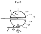
- Fig. 3 shows still another conventional moisture meter.
- Spherical mirrors 20 and 21 are disposed with the openings covered by dustproof glass 22 and 23 and with the paper 3 sandwiched between them.
- rays which are applied by the light source 6 and which are made to be intermittent rays by the chopper wheel 8 having the two kinds of filters that are referred to above are applied to the paper 3 through an irradiation window 5.
- the rays which penetrate the paper 3 or which are scattered by the paper 3 reach the light detector 12 after penetrating the paper 3 a plurality of times by being reflected at the inner surface of the sphere and by being applied to the paper 3 again.
- the computing of V R /V M is conducted in the same way as in the examples which are shown in Figs. 1 and 2 by a computing unit (not shown) using the detected rays and an electric signal which is related to the moisture of the paper 3 is outputted.
- V R /V M the ratio of the output V R of the R rays which penetrate the paper to the output V M of the M rays which penetrate the paper, that is, V R /V M is computed and an electric signal which is related to the moisture weight of the paper is obtained.
- the number of calibration curves which can be inputted to the computer is limited (for example, eight) and all objects to be measured can not be covered.
- the gap between the calibration curves is big.
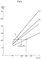
- Fig. 4 shows calibration curves which are obtained using three kinds of samples in the conventional moisture meter which is shown in Fig. 2.
- the vertical axis designates the output of the moisture meter which is given by K ⁇ (V R /V M ) (K: constant).
- the horizontal axis designates the moisture weight [g/m 2 ] of the paper.
- C 1 is a calibration curve when the basis weight of the paper is small
- C 2 is a calibration curve when the basis weight of the paper is medium
- C 3 is a calibration curve when the basis weight of the paper is large.
- the output of the moisture meter according to the calibration curve C 1 is the smallest and the output of the moisture meter according to the calibration curve C 3 is the largest.
- the reason that the output according to the calibration curve C 3 is larger even the moisture weight is the same is supposed to be that, when the basis weight is large, the number of times of the reflection and scattering within the paper increases, the optical path length becomes substantially longer, the M rays are absorbed by moisture more, and the value of the output V M becomes smaller.
- the moisture weight is 25 [g/m 2 ]
- the output of the moisture meter according to the calibration curve C 1 is regarded as the standard, there is a gap D 1 between the calibration curve C 1 and the calibration curve C 3 which gap D 1 is 12.5[g/m 2 ] if converted into moisture weight.
- the gap is large, a gap d 1 between an object to be measured which is shown by a broken line and the calibration curve C 2 which is selected as the calibration curve, the characteristics of which are the nearest to that of the object, is large, which causes error of measurement.
- the output according to the conventional system is shown as moisture weight, but generally, as a value according to which the quality of paper is to be controlled, moisture percentage is more convenient. Therefore, in addition to moisture weight, the basis weight of the paper is obtained to calculate moisture percentage.
- the one which is shown in Fig. 1 has advantages that the arrangement is simple and the attenuation of the quantity of rays is small, but on the other hand, as the object to be measured is only one point of the paper, there is a problem that, if the paper is thin, the moisture meter can not be sensitive.
- the moisture meter which is shown in Fig. 2 as the optical axis of the light emitting portion and the optical axis of the light detecting portion are misaligned, the number of times of meeting of the rays with the paper is large.
- the range of the rays which are scattered at the paper is 180° at the widest, and rays which meets with the paper only once are included. Therefore, the sensitivity of the moisture meter is not satisfactory. Further, there is a problem that if the optical axis of the light emitting portion is shifted more from the optical axis of the light detecting portion in order to decrease the influence of rays which penetrate the paper only once, the quantity of rays is decreased (The conventional moisture meter is designed so that the optical axes of the light emitting portion and of the light detecting portion may be shifted from each other by about 60mm, and the distance between the upper reflector and the lower reflector may be about 6-8mm).
- the present invention is made to solve the problems of conventional moisture meters which are referred to above, and the object of the present invention is to provide a device for measuring characteristics of paper and an infrared ray moisture meter in which transmission and scattering by paper is done enough independent of whether the paper is thin or thick, the sensitivity of which is high, and in which attenuation of rays is small and error of measurement with respect to misalignment in a horizontal plane is small, and to provide an infrared ray moisture meter in which the influence of the quality of paper is lowered, the shift of calibration curves is small, and moisture percentage is directly output.
- a device device for measuring characteristics of paper comprising a first reflector, a second reflector being disposed opposite said first reflector with a space therebetween for paper to be examined to be movable therethrough, means for allowing light to enter the space between the reflectors so as to pass through the paper to be examined, and detecting means for detecting light passed through the paper to be examined for measuring physical characteristics of the paper according to a signal from the detecting means, characterized in that said first reflector has a first return portion provided at a periphery thereof for returning light, said second reflector has a second return portion provided at a periphery thereof for returning light, a shielding plate is disposed between one of said reflectors and the paper, said shielding plate having two mirror finished sides and comprising means for guiding light that has passed through the paper to be examined to the detecting means, wherein said first and second return portions of the first and second reflectors reflecting the light within the space reaching the periphery of the reflectors to return towards the shield
- an infrared ray moisture meter for measuring a moisture content of paper, characterized by comprising such a device for measuring characteristics of paper according to the invention, means for applying to said means for allowing light to enter the space between the reflectors so as to pass through the paper to be examined infrared light of a first wavelength which is absorbed by moisture, infrared light of a second wavelength which is absorbed by cellulose, and infrared light of a third wavelength which is absorbed by neither moisture nor cellulose, said detecting means for detecting light passed through the paper to be examined is adapted to detect the light of the above wavelengths and to generate output signals corresponding thereto, respectively, and calculating means for calculating the moisture content of the paper from the output signals of the detecting means.
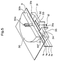
- Fig. 5 is a partial sectional perspective view which shows an embodiment of the invention of a device for measuring characteristics of paper to be used in an infrared ray moisture meter of the present invention.
- Fig. 5 the side which faces paper 3 of an upper or first reflector 30 is mirror finished.
- a light emitting hole 30a is formed at the center of the upper reflector 30.
- a return ring 30b is formed at the peripheral portion of the upper reflector 30. The return ring 30b is convex and the section of its inner circumference face meets at about 60° to the perpendicular of the mirror finished face.
- the side which faces the paper 3 of a lower or second reflector 31 is also mirror finished.
- a light detecting hole 31a is formed at the center of the lower reflector 31.
- a return ring 31b is formed at the peripheral portion of the lower reflector 31. The return ring 31b is convex and the section of its inner circumference face meets at about 60° to the perpendicular of the mirror finished face.
- Both of the sides of a shielding plate 32 are mirror finished.
- a conical protrusion (a conical mirror) 33 the surface of which is mirror finished is provided at the center of one of the sides of the shielding plate 32.
- the shielding plate 32 is fixed by a plurality of supporting poles (not shown) in the space between the lower reflector 31 and the paper 3 so as to be as high as the upper portion of the return ring 31b of the lower reflector 31.
- the conical mirror 33 is disposed on the side of the light detecting hole 31a.
- the center of the shielding plate 32 is preferably aligned with the axis of the upper reflector 30 and the axis of the lower reflector 31.
- the upper and lower reflectors 30 and 31 sandwich the paper 3 the moisture contained in which is to be measured.
- the upper and lower reflectors 30 and 31 are disposed so as to be as adjacent as possible to each other taking necessary allowable range into consideration and form light emitting space 34 and light detecting space 35.
- a light source is disposed over the light emitting hole 30a which light source applies M rays the wavelength of which is 1.94 ⁇ m and which is absorbed by moisture and R rays the wavelength of which is 1.8 ⁇ m and which is not absorbed by moisture.
- Elements such as a calculating portion which conducts calculation of moisture based on output of a light detector 12 which are necessary for a moisture meter are provided at the subsequent stage of the light detector 12.
- the applicant of the present invention has conducted an experiment under the condition that the outer diameter of the upper and the lower reflectors is 60mm, the height h1 of the upper return ring 30b is 2.5mm, the height h2 of the lower return ring 31b is 5.0mm, the distance h3 from the upper return ring 30b to the paper and the distance h4 from the lower return ring 31b to the paper are 2.0mm, the diameter of the shielding plate 32 is 30mm, the distance from the surface of the shielding plate to the paper is 2.0mm, the diameter of the light emitting hole 30a is 3mm, the diameter of the light detecting hole 31a is 18mm, and all other conditions are the same as that of a conventional moisture meter.
- Figs. 6 and 7 show calibration curves of the conventional moisture meter which is shown in Fig. 2 and the moisture meter of the present invention which is referred to above when, with respect to six kinds of paper, MW (moisture weight per unit area) is found based on a signal of measurement (V R /V M ) and the moisture percentage of the paper (MW/BW ⁇ 100% ... BW; paper weight per unit area) is calculated based on the above value so that measurement may be conducted within an accuracy of ⁇ 0.1% (an accuracy of ⁇ 0.1% shall mean, for example, when the moisture percentage is 5%, the error of measurement is within the range of 4.9% - 5.1%).
- V R /V M signal of measurement
- BW paper weight per unit area
- rays which come from the light emitting hole first penetrate or are scattered by the paper. These rays are reflected between the shielding plate and the upper reflector and meet with the paper a plurality of times. After the rays reach the periphery of the shielding plate, a part of the rays repeat diffraction between the lower reflector and the rear surface of the shielding plate and then reach the light detector. On the other hand, rays which repeat meeting with the paper further toward the periphery of the reflectors are returned by the return rings and again reach the periphery of the shielding plate, and a part of the rays are diffracted toward the rear surface of the shielding plate, repeat penetration and scattering, and reach the light detector. As a result, rays which are low in sensitivity of moisture detection, for example, rays which penetrate the paper only once, do not reach the light detector, which leads to an improvement of sensitivity.
- the moisture meter is arranged to return rays to the side of the light detector (in the direction of the center) by the return rings, the confining effect is made to be high, the quantity of rays of detection is made to be large, and the same optical system can measure moisture of both paper of low basis weight (for example, about 30g/m 2 ) and paper of high basis weight (for example, about 150g/m 2 ).
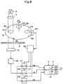
- Fig. 8 is a theoretical block diagram of an infrared ray moisture meter with which the influence of the quality of paper is lowered, the shift of the calibration curves is made to be small, and moisture percentage can directly be outputted.
- a numeral 6 designates a lamp and a numeral 7 designates a condenser lens.
- Filters 41, 42, and 43 each of which selectively transmits infrared rays of a predetermined wavelength range are disposed on a filter wheel 8 so as to be disposed on a concentric circle of the filter wheel 8.
- Four cut-outs 8a, 8b, 8c, and 8d for generating a synchronisation signal are provided at the periphery of the filter wheel 8.
- a photo interruptor 44 in which an LED and a phototransistor are disposed so as to face each other and so as to sandwich the peripheral portion of the filter wheel 8 generates a synchronisation pulse every time the cut-out 8a, 8b, 8c, or 8d passes the photo interruptor 44.
- a synchronisation signal circuit 45 generates a synchronisation signal based on a synchronisation pulse from the photo interruptor 44.
- a numeral 3 designates paper to be measured
- a numeral 12 designates a light detector
- a numeral 46 designates an amplifier.
- Sample-and-hold circuits 47, 48, and 49 convert an alternating current signal which is given by the light detector 12 to a direct current signal according to a synchronisation signal from the synchronisation signal circuit 45.
- An arithmetic circuit 13 calculates signals which are given by the sample-and-hold circuits 47, 48, and 49 and generates moisture meter output V o .
- infrared rays the wavelength of which is 1.94 ⁇ m and whichpass the filter 41, infrared rays the wavelength of which is 2.1 ⁇ m and which pass the filter 42, and infrared rays the wavelength of which is 1.8 ⁇ m and which pass the filter 43 are applied by turns to the paper 3. Penetrating rays and scattered rays based on these three kinds of infrared rays are detected by the light detector 12.
- detection output V M with respect to the infrared rays the wavelength of which is 1.94 ⁇ m, detection output V C with respect to the infrared rays the wavelength of which is 2.1 ⁇ m, and detection output V R with respect to the infrared rays the wavelength of which is 1.8 ⁇ m are given in a form of an alternating current signal to the sample-and-hold circuits 47, 48, and 49.
- a synchronisation signal which is given to the circuits 47, 48, and 49 by the synchronisation signal circuit 45, the alternating current signal is converted to a direct current signal.
- the output V M , V C , and V R is outputted from the sample-and-hold circuits 47, 48, and 49, respectively.
- V o ⁇ ln(a ⁇ V M /V R ) ⁇ / ⁇ ln(b ⁇ V C /V R )
- V o becomes a function of only the moisture weight (MW) and the cellulose weight (CW) (MW/CW), and one calibration curve is made independent of whether the basis weight is large or small and what kind of pulp the paper is made of.
- Fig. 9 shows calibration curves of seven specimens of newsprint using a system of the present invention (as some of the calibration curves lie on another, five calibration curves are shown).
- the vertical axis shows V o as referred to above, and the horizontal axis shows MW/CW [%].
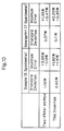
- Fig. 10 shows comparison between calibration curves of a moisture meter as an embodiment of the present invention which uses rays of three different wavelength range and calibration curves of a conventional moisture meter of two-filter method.
- the standard deviation of error of moisture percentage is lowered from 1.00 to 0.62 [%].
- the standard deviation of error of moisture percentage is lowered from 0.37 to 0.11 [%].
- the maximum error of moisture percentage with respect to the five specimens of sample, it is lowered from +3.65, -1.13 to +1.82, -1.12 [%].
- the maximum error of moisture percentage is lowered from +1.35, -0.47 to +0.20, -0.35 [%].
- the standard deviation means standard deviation of one calibration curve which is obtained from calibration curves of each sample so that the error of moisture percentage may be the minimum (a moisture percentage error minimum calibration curve) and calibration curves of the sample (the range of moisture percentage is from 2% to 12%).
- the maximum error is the maximum value of plus and minus of error of moisture percentage between the moisture percentage error minimum calibration curve and the calibration curves of the sample within the range of 2% and 12%.
- the infrared rays the wavelength of which is 1.94 ⁇ m, the infrared rays the wavelength of which is 2.1 ⁇ m, and the infrared rays the wavelength of which is 1.8 ⁇ m are separated by the filter wheel 8 and then applied to the paper 3.
- white light may be applied to the paper 3 and infrared rays of each wavelength may be separated from the light after penetrating or being scattered by the paper 3.
- ln is used as the functions, but a function such as l og or X- ⁇ (X-1) 2 / 2 ⁇ -1 of polynomial expansion may be used as long as the function outputs an approximate value of logarithm.
- an infrared ray moisture meter with which moisture of paper is measured with the influence of the quality of the paper lowered, with shift of the calibration curve small, and which can directly output moisture percentage can be materialized.
- a light emitting portion and a light detecting portion are disposed on two arms, respectively, which arms are parallel to each other, paper moves between the arms, and further, in order to measure the whole area of the width of the paper, the light emitting portion and the light detecting portion move orthogonally with respect to the machine direction along the arms. Accordingly, the position of the upper reflector 30 disposed on the light emitting side and the position of the lower reflector 31 disposed on the light detecting side (see Fig. 1) are not always aligned with each other and misalignment, for example, in a horizontal direction or the vertical -direction is caused.
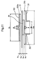
- Fig. 11 is a partial sectional view of an embodiment with which error caused by misalignment of the light emitting portion and the light detecting portion is prevented from happening.
- an improvement in the horizontal misalignment as referred to above is made.
- the outer diameter of the upper reflector 30 is made to be smaller than the outer diameter of the lower reflector 31.
- the lower reflector 31 is necessary for increasing the quantity of rays of detection.
- the range of measuring moisture is the area where the upper reflector 30 exists.
- the sensitivity of moisture detection and the quantity of rays are maintained at a predetermined level.
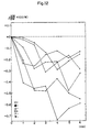
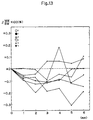
- Figs. 12 and 13 show an example of an experiment using six kinds of paper of the relationship of the misalignment and error of moisture percentage in case the outer diameter of the upper reflector 30 is formed to be the same size as the outer diameter of the lower reflector 31 (Fig. 12) and in case the outer diameter of the upper reflector 30 is formed to be smaller than the outer diameter of the lower reflector 31 (Fig. 13) of the moisture meter using the rays of three different wavelength ranges of the present invention which is shown in Fig. 8.
- the results are the errors of moisture percentage from a standard moisture percentage when there is no alignment (the upper reflector 30 is coaxial with the lower reflector 31) of moisture percentage (MW/BWX100%) found by signals which are obtained by moving the upper head by every 1mm from the center with the lower head fixed.
- the movement characteristics can be greatly improved (generally, the quantity of misalignment between the upper and the lower heads is about ⁇ 1.5mm, but in Fig. 12, with respect to tracing paper-1 and tracing paper-2, the error as to the misalignment of 2mm is over 0.2%. On the other hand, in Fig. 13, when the misalignment is 2mm, the error is within 0.2% with respect to every kind of paper, and the error of moisture percentage is improved).
- a moisture meter in which the outer diameters D 1 and D 2 of the upper and the lower reflectors 30 and 31 are both 40mm and a moisture meter in which the outer diameter D 1 of the upper reflector 30 is 40mm and the outer diameter D 2 of the lower reflector 31 is 50mm are used.
- the diameter d 1 of the light emitting hole, the diameter d 2 of the light detecting hole, and the diameter d 3 of the shielding plate are commonly 3mm, 18mm, and 22mm, respectively.
- the height h 1 of the return ring 30a is 2.5mm
- the height h 2 of the return ring 30b is 5.0mm
- the distances h 3 and h 4 from the return rings 30a and 30b to the paper are both 2.0mm.
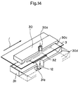
- Fig. 14 is a sectional perspective view which shows an embodiment of the present invention in which the measurement width is made to be smaller without lowering the sensitivity of detection.
- Like reference characters in Figs. 5 and 14 designate like elements and duplicated description is omitted.
- the upper and the lower reflectors 30 and 31 are formed to be rectangular.
- the longer side of the upper reflector 30 is 140mm
- the shorter side of the upper reflector 30 is 40mm
- the longer side of the lower reflector 31 is 150mm
- the shorter side of the lower reflector 31 is 50mm.
- the height h 1 and h 2 of the return rings 30b and 31b is 9.6mm from the reflection face.
- the diameter of the light emitting hole 30a is 3mm and the diameter of the light detecting hole 31a is 18mm.
- the shielding plate 32 is square-like one side of which square is about 40mm, both of which sides in the longitudinal direction of the lower reflector 31 are bent so as to be broadened toward the ends, the bent portions being in contact with the lower reflector and being fixed around the center of the lower reflector so that opened portions are located in the machine direction.
- This device is fixed to a mounting head with its longitudinal direction being along the machine direction.
- the penetrating and scattered rays do not come from the cross direction and only rays which penetrate and are scattered along the openings in the machine direction are detected.
- the measurement width in the cross direction is more important than the measurement width in the machine direction.
- This arrangement is short in the cross direction and long in the machine direction, and therefore, the measurement width can be shortened without lowering the sensitivity of detection.
- the upper and lower reflectors are rectangular, but they may be formed to be ellipse-like the longer sides of which are straight and the shorter sides of which are semicircular.
Landscapes
- Physics & Mathematics (AREA)
- Health & Medical Sciences (AREA)
- Life Sciences & Earth Sciences (AREA)
- Chemical & Material Sciences (AREA)
- Immunology (AREA)
- Biochemistry (AREA)
- General Health & Medical Sciences (AREA)
- General Physics & Mathematics (AREA)
- Analytical Chemistry (AREA)
- Pathology (AREA)
- Spectroscopy & Molecular Physics (AREA)
- Engineering & Computer Science (AREA)
- Food Science & Technology (AREA)
- Medicinal Chemistry (AREA)
- Investigating Or Analysing Materials By Optical Means (AREA)
- Analysing Materials By The Use Of Radiation (AREA)
Claims (9)
- Vorrichtung zum Messen oder Bestimmen der Eigenschaften von Papier, umfassend:einen ersten Reflektor (30),einen zweiten Reflektor (31), der dem ersten Reflektor (30) mit einem dazwischen gebildeten Zwischenraum (34) für Hindurchbewegung des zu untersuchenden Papiers (3) gegenüberstehend angeordnet ist,ein Mittel (30a) zur Ermöglichung eines Eintritts von Licht in den Zwischenraum (34) zwischen den Reflektoren (30, 31), um das Licht das zu untersuchende Papier (3) durchdringen zu lassen, undein Detektionsmittel (12) zum Detektieren bzw. Erfassen des durch das zu untersuchende Papier (3) hindurchgedrungenen Lichts zwecks Messung physikalischer Eigenschaften des Papiers (3) entsprechend einem Signal vom Detektionsmittel (12),dadurch gekennzeichnet, daßder erste Reflektor (30) einen an seinem Umfang vorgesehenen ersten Rückstrahlabschnitt (return portion) (30b, 30c) zum Rückstrahlen oder Zurückleiten von Licht aufweist,der zweite Reflektor (31) einen an seinem Umfang vorgesehenen zweiten Rückstrahlabschnitt (31b, 30d) zum Rückstrahlen von Licht aufweist, (und)zwischen einem der Reflektoren (30, 31) und dem Papier (3) eine Abschirmplatte (32) angeordnet ist, die zwei Spiegelschliff-Seiten und ein Mittel (33) zum Leiten von Licht, welches das zu untersuchende Papier (3) durchdrungen hat, zum Detektionsmittel (12) aufweist,wobei die ersten und zweiten Rückstrahlabschnitte (30b, 30c, 31b, 30d) der ersten und zweiten Reflektoren (30, 31) das im Zwischenraum (34) den Umfang der Reflektoren (30, 31) erreichende Licht reflektieren, um es zur Abschirmplatte (32) zurückzuwerfen.
- Vorrichtung nach Anspuch 1, dadurch gekennzeichnet, daß erster und zweiter Reflektor (30, 31) scheibenförmig sind und praktisch gleiche Außendurchmesser besitzen.
- Vorrichtung nach Anspruch 1, dadurch gekennzeichnet, daß erster und zweiter Reflektor (30, 31) scheibenförmig sind und unterschiedliche Außendurchmesser besitzen.
- Vorrichtung nach Anspruch 3, dadurch gekennzeichnet, daß der Außendurchmesser des ersten Reflektors (30) kleiner ist als der Außendurchmesser des zweiten Reflektors (31).
- Vorrichtung nach Anspruch 1, dadurch gekennzeichnet, daß erster und zweiter Reflektor (30, 31) jeweils rechteckig geformt sind, wobei die längeren Abmessungen der jeweiligen Reflektoren voneinander verschieden sind.
- Vorrichtung nach Anspruch 5, dadurch gekennzeichnet, daß die längeren Seiten von erstem und zweiten Reflektor (30, 31) in der Bewegungsrichtung des Papiers angeordnet sind.
- Vorrichtung nach Anspruch 1, dadurch gekennzeichnet, daß erster und zweiter Reflektor (30, 31) elliptisch geformt sind.
- Vorrichtung nach einem der Ansprüche 1 bis 7, dadurch gekennzeichnet, daß die am Umfang der Reflektoren (30, 31) vorgesehenen ersten und zweiten Rückstrahlabschnitte (30b, 30c, 31b, 30d) als konvexe Ringe geformt sind, wobei ein(e) Schnitt(linie) (section) ihrer Innenumfangsfläche unter etwa 60° zu einer senkrecht zu den Oberflächen der Reflektoren (30, 31) stehenden Linie geneigt ist.
- Infrarot-Feuchtigkeitsmeßgerät zum Messen eines Feuchtigkeitsgehalts von Papier, gekennzeichnet durcheine Vorrichtung zum Messen oder Bestimmen der Eigenschaften von Papier nach einem der Ansprüche 1 bis 8,Mittel zum Einstrahlen (applying) von Infrarotlicht einer ersten Wellenlänge, das von Feuchtigkeit absorbiert wird, Infrarotlicht einer zweiten Wellenlänge, das von Zellulose absorbiert wird, und Infrarotlicht einer dritten Wellenlänge, das weder von Feuchtigkeit noch von Zellulose absorbiert wird, in das Mittel (30a) zur Ermöglichung eines Eintritts von Licht in den Zwischenraum (34) zwischen den Reflektoren (30, 31), um das Licht das zu untersuchende Papier (3) durchdringen zu lassen,wobei das Detektionsmittel (12) zum Detektieren des durch das zu untersuchende Papier (3) hindurchgedrungenen Lichts das Licht der oben angegebenen Wellenlängen zu detektieren bzw. zu erfassen und jeweils entsprechende Ausgangssignale (VM, VC, VR) zu erzeugen vermag, undeine Recheneinheit (13) zum Berechnen des Feuchtigkeitsgehalts des Papiers anhand der Ausgangssignale (VM, VC, VR) des Detektionsmittels (12).
Applications Claiming Priority (4)
| Application Number | Priority Date | Filing Date | Title |
|---|---|---|---|
| JP2111539A JPH049644A (ja) | 1990-04-26 | 1990-04-26 | 紙質の影響を低減した赤外線水分計 |
| JP111539/90 | 1990-04-26 | ||
| JP454491 | 1991-01-18 | ||
| JP4544/91 | 1991-01-18 |
Publications (3)
| Publication Number | Publication Date |
|---|---|
| EP0453797A2 EP0453797A2 (de) | 1991-10-30 |
| EP0453797A3 EP0453797A3 (en) | 1992-03-04 |
| EP0453797B1 true EP0453797B1 (de) | 1996-06-26 |
Family
ID=26338351
Family Applications (1)
| Application Number | Title | Priority Date | Filing Date |
|---|---|---|---|
| EP91104799A Expired - Lifetime EP0453797B1 (de) | 1990-04-26 | 1991-03-26 | Infrarotfeuchtigkeitsmessgerät |
Country Status (5)
| Country | Link |
|---|---|
| US (1) | US5087817A (de) |
| EP (1) | EP0453797B1 (de) |
| CA (1) | CA2038704C (de) |
| DE (2) | DE69120462T2 (de) |
| FI (1) | FI911634L (de) |
Families Citing this family (13)
| Publication number | Priority date | Publication date | Assignee | Title |
|---|---|---|---|---|
| BR9406736A (pt) * | 1993-06-02 | 1996-02-06 | Allied Signal Inc | Processo para medição e controle contínuos do grau de cura e do teor de resina de uma folha em movimento de "prepreg" de resina epóxi reforçada com fibra de vidro parcialmente curada |
| US5457319A (en) * | 1993-06-02 | 1995-10-10 | Alliedsignal Inc. | Process for measurement of the degree of cure and percent resin of glass-fiber reinforced epoxy resin prepreg |
| DE4441350C1 (de) * | 1994-11-21 | 1996-06-13 | Bohle L B Pharmatech Gmbh | Infrarotspektroskopische Meßvorrichtung für einen mit einem Rührwerk ausgerüsteten Mischgranulator und Vakuumtrockner zur Messung der Feuchtigkeit des Mischguts |
| IT1275684B1 (it) * | 1994-12-06 | 1997-10-17 | Electronics Systems S P A | Sistema e relativa apparecchiatura per la taratura di un sensore per la misurazione dell'umidita' di materiali in fogli nastri, o film |
| DE19701904C2 (de) * | 1997-01-21 | 2002-02-14 | Michael Tummuscheit | Vorrichtung zur quantitativen Bestimmung der Oberflächenfeuchte mit Hilfe eines kombinierten Verfahrens |
| US6024740A (en) * | 1997-07-08 | 2000-02-15 | The Regents Of The University Of California | Circumferential ablation device assembly |
| US6986279B2 (en) * | 2000-08-22 | 2006-01-17 | Barnstead Thermolyne Corporation | Method and apparatus for determining liquid absorption of aggregate |
| US6486475B1 (en) | 2000-08-22 | 2002-11-26 | Barnstead-Thermolyne Corporation | Method and apparatus for determining liquid absorption of aggregate |
| JP2002245511A (ja) * | 2001-02-15 | 2002-08-30 | Hitachi Ltd | 紙質識別方法 |
| US20050127925A1 (en) * | 2003-12-10 | 2005-06-16 | Staples Peter E. | Moisture sensor |
| US8148690B2 (en) | 2009-09-24 | 2012-04-03 | ABB, Ltd. | Method and apparatus for on-line web property measurement |
| GB2533589A (en) * | 2014-12-22 | 2016-06-29 | Ndc Infrared Eng Ltd | Measurement of porous film |
| US11231363B2 (en) * | 2018-05-31 | 2022-01-25 | Psm International, Inc. | Quality measurement method and quality measurement device for long sheet material |
Family Cites Families (4)
| Publication number | Priority date | Publication date | Assignee | Title |
|---|---|---|---|---|
| US4027161A (en) * | 1976-04-05 | 1977-05-31 | Industrial Nucleonics Corporation | Minimizing wave interference effects on the measurement of thin films having specular surfaces using infrared radiation |
| US4052615A (en) * | 1976-07-30 | 1977-10-04 | Industrial Nucleonics Corporation | Spherical cavity method and apparatus for measuring a sheet material property using infrared radiation |
| DE2910673C2 (de) * | 1979-03-19 | 1985-08-08 | Paul Lippke Gmbh & Co Kg, 5450 Neuwied | Verfahren zum berührungslosen Messen des absoluten Gehaltes eines Stoffes(Beisubstanz) in einer die Form eines dünnen Filmes aufweisenden Mischung(Hauptsubstanz und Beisubstanz) mehrerer Stoffe, insbesondere zum Messen des absoluten Gehaltes von Wasser in Papier |
| CA1319273C (en) * | 1988-03-10 | 1993-06-22 | Steven Perry Sturm | Clay sensor |
-
1991
- 1991-03-20 CA CA002038704A patent/CA2038704C/en not_active Expired - Fee Related
- 1991-03-25 US US07/674,810 patent/US5087817A/en not_active Expired - Fee Related
- 1991-03-26 DE DE69120462T patent/DE69120462T2/de not_active Expired - Fee Related
- 1991-03-26 EP EP91104799A patent/EP0453797B1/de not_active Expired - Lifetime
- 1991-03-26 DE DE199191104799T patent/DE453797T1/de active Pending
- 1991-04-05 FI FI911634A patent/FI911634L/fi not_active Application Discontinuation
Non-Patent Citations (2)
| Title |
|---|
| PATENT ABSTRACTS OF JAPAN, Vol. 13, No. 209 (P-871)(3557), 17 May 1989; & JP-A-1025038 * |
| PATENT ABSTRACTS OF JAPAN, Vol. 13, No. 215, (P.874)(3563), 19 May 1989; & JP-A-1032153 * |
Also Published As
| Publication number | Publication date |
|---|---|
| CA2038704A1 (en) | 1991-10-27 |
| EP0453797A2 (de) | 1991-10-30 |
| DE453797T1 (de) | 1992-02-27 |
| US5087817A (en) | 1992-02-11 |
| FI911634A7 (fi) | 1991-10-27 |
| CA2038704C (en) | 1996-01-30 |
| FI911634A0 (fi) | 1991-04-05 |
| EP0453797A3 (en) | 1992-03-04 |
| DE69120462T2 (de) | 1996-11-28 |
| DE69120462D1 (de) | 1996-08-01 |
| FI911634L (fi) | 1991-10-27 |
Similar Documents
| Publication | Publication Date | Title |
|---|---|---|
| US4859062A (en) | Optoelectrical measuring system and apparatus | |
| US4254337A (en) | Infrared interference type film thickness measuring method and instrument therefor | |
| US3652863A (en) | Detection of faults in transparent material using lasers | |
| US4081215A (en) | Stable two-channel, single-filter spectrometer | |
| EP0453797B1 (de) | Infrarotfeuchtigkeitsmessgerät | |
| US3667846A (en) | Optical surface inspection apparatus | |
| US4429225A (en) | Infrared thickness measuring device | |
| EP0396409A3 (de) | Ellipsometrische Vorrichtung mit hohem Auflösungsvermögen | |
| CA2070330C (en) | High resolution spectroscopy system | |
| JPS5839931A (ja) | 赤外線を使用してプラスチツクフイルムの特性を測定する方法 | |
| US3965356A (en) | Apparatus for measuring a predetermined characteristic of a material using two or more wavelengths of radiation | |
| FI78355B (fi) | Metod foer maetning av glans och apparatur foer tillaempning av metoden. | |
| US4536090A (en) | Optical multi-beam gas measuring apparatus | |
| JPS6017340A (ja) | 紙の光学的な特性を測定する装置 | |
| WO1999014579A1 (en) | Method and apparatus for measuring properties of paper | |
| US4295743A (en) | Apparatus for determining faults in strip material | |
| DE4105509C2 (de) | Streulichtmeßanordnung zur Untersuchung der Oberflächenrauheit | |
| KR840002359B1 (ko) | 적외선 필름 두께 측정기 | |
| US3211051A (en) | Optical measuring device for obtaining a first derivative of intensity with respect to wavelength | |
| JPH02114146A (ja) | 構造部品や試験片における亀裂長さやひずみを測定する方法とその装置 | |
| JP2932783B2 (ja) | シ―ト状物体の特性測定装置 | |
| US5170224A (en) | Laser wavelength measuring device | |
| JP3057270B2 (ja) | シ―ト状物体の特性測定装置 | |
| RU1770850C (ru) | Способ определени спектральных направленно-полусферических коэффициентов отражени образцов | |
| GB2129932A (en) | Position and/or dimensions of objects |
Legal Events
| Date | Code | Title | Description |
|---|---|---|---|
| PUAI | Public reference made under article 153(3) epc to a published international application that has entered the european phase |
Free format text: ORIGINAL CODE: 0009012 |
|
| 17P | Request for examination filed |
Effective date: 19910423 |
|
| AK | Designated contracting states |
Kind code of ref document: A2 Designated state(s): DE GB |
|
| PUAL | Search report despatched |
Free format text: ORIGINAL CODE: 0009013 |
|
| DET | De: translation of patent claims | ||
| AK | Designated contracting states |
Kind code of ref document: A3 Designated state(s): DE GB |
|
| 17Q | First examination report despatched |
Effective date: 19940113 |
|
| GRAH | Despatch of communication of intention to grant a patent |
Free format text: ORIGINAL CODE: EPIDOS IGRA |
|
| GRAA | (expected) grant |
Free format text: ORIGINAL CODE: 0009210 |
|
| AK | Designated contracting states |
Kind code of ref document: B1 Designated state(s): DE GB |
|
| REF | Corresponds to: |
Ref document number: 69120462 Country of ref document: DE Date of ref document: 19960801 |
|
| REG | Reference to a national code |
Ref country code: GB Ref legal event code: 746 Effective date: 19970326 |
|
| PLBE | No opposition filed within time limit |
Free format text: ORIGINAL CODE: 0009261 |
|
| STAA | Information on the status of an ep patent application or granted ep patent |
Free format text: STATUS: NO OPPOSITION FILED WITHIN TIME LIMIT |
|
| 26N | No opposition filed | ||
| PGFP | Annual fee paid to national office [announced via postgrant information from national office to epo] |
Ref country code: GB Payment date: 19990325 Year of fee payment: 9 |
|
| PGFP | Annual fee paid to national office [announced via postgrant information from national office to epo] |
Ref country code: DE Payment date: 19990406 Year of fee payment: 9 |
|
| PG25 | Lapsed in a contracting state [announced via postgrant information from national office to epo] |
Ref country code: GB Free format text: LAPSE BECAUSE OF NON-PAYMENT OF DUE FEES Effective date: 20000326 |
|
| GBPC | Gb: european patent ceased through non-payment of renewal fee |
Effective date: 20000326 |
|
| PG25 | Lapsed in a contracting state [announced via postgrant information from national office to epo] |
Ref country code: DE Free format text: LAPSE BECAUSE OF NON-PAYMENT OF DUE FEES Effective date: 20010103 |