EP0453804A1 - Filtre pour aquarium - Google Patents
Filtre pour aquarium Download PDFInfo
- Publication number
- EP0453804A1 EP0453804A1 EP19910104948 EP91104948A EP0453804A1 EP 0453804 A1 EP0453804 A1 EP 0453804A1 EP 19910104948 EP19910104948 EP 19910104948 EP 91104948 A EP91104948 A EP 91104948A EP 0453804 A1 EP0453804 A1 EP 0453804A1
- Authority
- EP
- European Patent Office
- Prior art keywords
- filter
- filter according
- compartment
- outlet
- inlet
- Prior art date
- Legal status (The legal status is an assumption and is not a legal conclusion. Google has not performed a legal analysis and makes no representation as to the accuracy of the status listed.)
- Granted
Links
Images



Classifications
-
- C—CHEMISTRY; METALLURGY
- C02—TREATMENT OF WATER, WASTE WATER, SEWAGE, OR SLUDGE
- C02F—TREATMENT OF WATER, WASTE WATER, SEWAGE, OR SLUDGE
- C02F3/00—Biological treatment of water, waste water, or sewage
- C02F3/02—Aerobic processes
- C02F3/06—Aerobic processes using submerged filters
-
- A—HUMAN NECESSITIES
- A01—AGRICULTURE; FORESTRY; ANIMAL HUSBANDRY; HUNTING; TRAPPING; FISHING
- A01K—ANIMAL HUSBANDRY; AVICULTURE; APICULTURE; PISCICULTURE; FISHING; REARING OR BREEDING ANIMALS, NOT OTHERWISE PROVIDED FOR; NEW BREEDS OF ANIMALS
- A01K63/00—Receptacles for live fish, e.g. aquaria; Terraria
- A01K63/04—Arrangements for treating water specially adapted to receptacles for live fish
- A01K63/045—Filters for aquaria
-
- B—PERFORMING OPERATIONS; TRANSPORTING
- B01—PHYSICAL OR CHEMICAL PROCESSES OR APPARATUS IN GENERAL
- B01D—SEPARATION
- B01D24/00—Filters comprising loose filtering material, i.e. filtering material without any binder between the individual particles or fibres thereof
- B01D24/007—Filters comprising loose filtering material, i.e. filtering material without any binder between the individual particles or fibres thereof with multiple filtering elements in series connection
-
- B—PERFORMING OPERATIONS; TRANSPORTING
- B01—PHYSICAL OR CHEMICAL PROCESSES OR APPARATUS IN GENERAL
- B01D—SEPARATION
- B01D24/00—Filters comprising loose filtering material, i.e. filtering material without any binder between the individual particles or fibres thereof
- B01D24/02—Filters comprising loose filtering material, i.e. filtering material without any binder between the individual particles or fibres thereof with the filter bed stationary during the filtration
- B01D24/10—Filters comprising loose filtering material, i.e. filtering material without any binder between the individual particles or fibres thereof with the filter bed stationary during the filtration the filtering material being held in a closed container
- B01D24/14—Downward filtration, the container having distribution or collection headers or pervious conduits
-
- B—PERFORMING OPERATIONS; TRANSPORTING
- B01—PHYSICAL OR CHEMICAL PROCESSES OR APPARATUS IN GENERAL
- B01D—SEPARATION
- B01D24/00—Filters comprising loose filtering material, i.e. filtering material without any binder between the individual particles or fibres thereof
- B01D24/38—Feed or discharge devices
- B01D24/40—Feed or discharge devices for feeding
-
- B—PERFORMING OPERATIONS; TRANSPORTING
- B01—PHYSICAL OR CHEMICAL PROCESSES OR APPARATUS IN GENERAL
- B01D—SEPARATION
- B01D24/00—Filters comprising loose filtering material, i.e. filtering material without any binder between the individual particles or fibres thereof
- B01D24/38—Feed or discharge devices
- B01D24/42—Feed or discharge devices for discharging filtrate
-
- B—PERFORMING OPERATIONS; TRANSPORTING
- B01—PHYSICAL OR CHEMICAL PROCESSES OR APPARATUS IN GENERAL
- B01D—SEPARATION
- B01D24/00—Filters comprising loose filtering material, i.e. filtering material without any binder between the individual particles or fibres thereof
- B01D24/48—Filters comprising loose filtering material, i.e. filtering material without any binder between the individual particles or fibres thereof integrally combined with devices for controlling the filtration
- B01D24/4876—Filters comprising loose filtering material, i.e. filtering material without any binder between the individual particles or fibres thereof integrally combined with devices for controlling the filtration in which the filtering elements are moved between filtering operations; particular measures for removing or replacing the filtering elements
-
- B—PERFORMING OPERATIONS; TRANSPORTING
- B01—PHYSICAL OR CHEMICAL PROCESSES OR APPARATUS IN GENERAL
- B01D—SEPARATION
- B01D25/00—Filters formed by clamping together several filtering elements or parts of such elements
- B01D25/22—Cell-type filters
- B01D25/26—Cell-type stack filters
-
- B—PERFORMING OPERATIONS; TRANSPORTING
- B01—PHYSICAL OR CHEMICAL PROCESSES OR APPARATUS IN GENERAL
- B01D—SEPARATION
- B01D35/00—Filtering devices having features not specifically covered by groups B01D24/00 - B01D33/00, or for applications not specifically covered by groups B01D24/00 - B01D33/00; Auxiliary devices for filtration; Filter housing constructions
- B01D35/14—Safety devices specially adapted for filtration; Devices for indicating clogging
-
- B—PERFORMING OPERATIONS; TRANSPORTING
- B01—PHYSICAL OR CHEMICAL PROCESSES OR APPARATUS IN GENERAL
- B01D—SEPARATION
- B01D35/00—Filtering devices having features not specifically covered by groups B01D24/00 - B01D33/00, or for applications not specifically covered by groups B01D24/00 - B01D33/00; Auxiliary devices for filtration; Filter housing constructions
- B01D35/14—Safety devices specially adapted for filtration; Devices for indicating clogging
- B01D35/147—Bypass or safety valves
-
- B—PERFORMING OPERATIONS; TRANSPORTING
- B01—PHYSICAL OR CHEMICAL PROCESSES OR APPARATUS IN GENERAL
- B01D—SEPARATION
- B01D35/00—Filtering devices having features not specifically covered by groups B01D24/00 - B01D33/00, or for applications not specifically covered by groups B01D24/00 - B01D33/00; Auxiliary devices for filtration; Filter housing constructions
- B01D35/26—Filters with built-in pumps filters provided with a pump mounted in or on the casing
-
- Y—GENERAL TAGGING OF NEW TECHNOLOGICAL DEVELOPMENTS; GENERAL TAGGING OF CROSS-SECTIONAL TECHNOLOGIES SPANNING OVER SEVERAL SECTIONS OF THE IPC; TECHNICAL SUBJECTS COVERED BY FORMER USPC CROSS-REFERENCE ART COLLECTIONS [XRACs] AND DIGESTS
- Y02—TECHNOLOGIES OR APPLICATIONS FOR MITIGATION OR ADAPTATION AGAINST CLIMATE CHANGE
- Y02W—CLIMATE CHANGE MITIGATION TECHNOLOGIES RELATED TO WASTEWATER TREATMENT OR WASTE MANAGEMENT
- Y02W10/00—Technologies for wastewater treatment
- Y02W10/10—Biological treatment of water, waste water, or sewage
Definitions
- the invention relates to a filter for aquariums of the type mentioned in the preamble of claim 1.
- a filter of this type is known (DE-PS 27 00 030), which works as an alternating lifting-lowering filter.
- This filter is designed as an external filter and connected to the aquarium tank via an inlet line.
- the filter contains only one filter compartment.
- the inlet is from above into a room above the filter compartment.
- a bottom chamber is formed below the filter compartment.
- An inverted U-shaped line with the free pipe end opens into the bottom chamber, a pump being connected in this line, which sucks water that collects from the bottom chamber and returns it to the tank via a return line leading to the aquarium tank.
- a bypass line is provided for safety reasons in the event of a blockage of the filter compartment between the upper space, where the supply takes place, and the bottom chamber, so that if the filter compartment is clogged, the water supplied above through the bypass line directly down into the bottom chamber can reach.
- the water is always extracted in the area of the floor chamber via the open end of one U-leg.
- the water level in the filter compartment drops down.
- the discharge quantity per unit of time is greater than the supply quantity per unit of time. Due to this design, the known filter results in a lifting-lowering operation.
- the filter is complicated with regard to the device which brings about the lifting-lowering function, since the inverted U-shaped tube to which the pump is connected passes through the filter mass in the filter compartment with both legs.
- the invention has for its object to provide a filter for aquariums of the type mentioned, in which the device that causes the lifting-lowering function is simple and inexpensive, enables long-term function of the filter and each filter compartment can be easily used by the user if necessary , also by lay people, can be removed from the filter.
- the overflow suction device which is unique to each filter compartment, is simple and reliable. It requires little space in the filter compartment so that a large volume of filter material can be accommodated there. In everything, the filter is reliable, and this for long-term operation. Should cleaning or the like nevertheless be necessary, even the layperson can quickly dismantle the individual components of the filter.
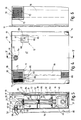
- a filter 10 for aquariums is shown schematically, which is designed in particular as an internal filter, which is contained in an aquarium tank 11 which is only indicated schematically and is held there removably on an aquarium wall 13 by means of two similar hanging brackets 12.
- the filter 10 has an approximately box-shaped housing 14 z. B. made of plastic.
- the housing 14 there is a bottom chamber 15 with a closed bottom 16 below.
- At least one filter compartment is provided above the bottom chamber 15.
- two filter compartments 17, 18 are placed vertically one above the other, both filter material 19, z. B. stones, gravel or the like. Contain.
- Ambient water from the aquarium basin 11 can be fed to the upper filter compartment 17 via an inlet 20 in the direction of the arrow, and this - based on the upper filter compartment 17 - can be supplied from above.
- the water After passing through the upper filter compartment 17, the water can be fed to the filter compartment 18 underneath and after passing through the bottom chamber 15 underneath and can be extracted from the bottom chamber 15 by means of a schematically indicated pump 21.
- the extracted water is returned to the aquarium tank 11 by means of the pump 21 via a line 22 connected to it.
- the filter 10 works in a known manner (DE-PS 27 00 030) as an alternating Lift-lower filter.
- DE-PS 27 00 030 the special mode of operation of such a lifting-lowering filter and in particular the strong oxygen enrichment achieved as a result is described in detail in the abovementioned text, so that reference can be made to avoid repetition.
- each filter compartment 17, 18 has at least one overflow suction device 23 or 24.
- These overflow suction lifters 23 and 24 operate on the principle of the lifter loop, also called the principle of the pipette washer.
- Each of these devices 23, 24 can also be regarded as an upside-down siphon. Details are explained below.
- each overflow suction lifter device 23, 24, its inlet 25 or 26 is arranged on the foot side and approximately at the level of the bottom 27 or 28 of the filter compartment 17 or 18.
- the outlet 29 opens to the filter compartment 18 below, while the outlet 30 of the lowermost filter compartment 18 opens down to the bottom chamber 15 and feeds it.
- Each filter compartment 17, 18 has its overflow suction device 23 or 24 on one side, namely in the case of all filter compartments 17, 18 on the same side, so that they are in a vertical direction with one another.
- the bottom 27 or 28 slopes towards the inlet 25 or 26 of the associated overflow suction device 23 or 24.
- Each filter compartment 17, 18 has a filter container 31 or 32 which is designed as an approximately open trough and which is of completely identical design, interchangeable and each also interchangeable in the housing 14 and z. B. can be easily and easily removed for cleaning purposes.
- Both the housing 14 and the filter container 31, 32 are made, for. B. made of plastic, and here made of plastic injection molded parts.
- Each overflow suction device 23, 24 has an outlet pipe 33, 34 which projects from the bottom 27 and 28 and runs vertically. With its lower end, the outlet pipe 33, 34 projects beyond the bottom 27 or 28 and forms the outlet 29 or 30 with the pipe end open there.
- the outlet pipe 33, 34 is an integral part of the bottom 27 or 28.
- each overflow suction lifter device 23, 24 has a valve tube 35 or 36 which is closed on the upper side and which is left with a radial annular space 37, 38 and thereby placed over the outlet tube 33 or 34 such that the closed upper side 39 or 40 of the valve tube 35 , 36, leaving an axial overflow space 41 or 42 at a distance above the open upper end of the outlet pipe 33 or 34.
- the respective top 39, 40 of the valve tube 35 and 36 with a slope in FIGS. 1 and 2 runs obliquely from the right to the left and down to the filter container 31 and 32, so that water striking it from above is drained off to the left.
- the respective valve pipe 35 or 36 has on its upper side 39 or 40 upwardly projecting guide walls 43 or 44 which delimit an inclined water channel.
- the respective valve tube 35, 36 can be designed on the upper side in cross section approximately similar to a blade.
- the guide walls 43, 44 form a U which is open to the left in FIGS. 1 and 2 and promote the drainage of the water which reaches it from above.
- Each valve tube 35, 36 contains in its tubular jacket foot-side passages which, for. B. are approximately arch-shaped. These passages form the inlet 25 or 26 of each overflow suction device 23 or 24. These approximately arch-shaped inlets 25 or 26 are distributed in the circumferential direction of each valve tube 35, 36.
- the water snaps into the outlet pipe 33, 34 through which the water flows, the water passing the outlet pipe 33, 34 at the open end through its outlet 29 or 30 leaves. If this snap situation is reached, the water runs z. B. from the upper filter container 31 to the lower end of the valve tube 35. It is thus emptied in this way, the upper filter container 31 relatively suddenly over the overflow suction device 23 down and into the filter container 32 below. The inflow amount of water, the is introduced into the upper filter container 31 is smaller than the discharge amount.
- the lower filter container 32 is also emptied via the overflow suction device 24 when the overcap level is reached, the emptying taking place through the outlet 30 into the bottom chamber 15. From there, the pump 21 pumps the water out of the bottom chamber 15 through the line 22 and leads this water back into the aquarium tank 11. The pump 21 runs continuously and continuously pumps water back through line 22 into the aquarium tank 11.
- the upper filter tank 31 empties into the next filter tank 32 via the overflow suction device 23 in the manner described, the water level lowers above the floor 27 down to the floor. As a result, air is taken up in the filter container 31. The surface of the filter material 19 absorbs atmospheric oxygen. Subsequent to the emptying cycle, the upper filter container 31, to which water is supplied from the aquarium basin 11 via the inlet 20, fills again to the level at which the overflow suction device 23 finally snaps over again.
- the respective valve tube 35, 36 is a separate component and is detachably inserted.
- the bottom chamber 15 has, on its side wall parts, raised support webs 45, 46, on which the filter container 32 located above is supported vertically.
- the filter containers 31, 32 are placed one above the other in the vertical direction and designed in such a way that the lower filter container 32 can support the filter container 31 located above it vertically.
- the pump 21 arranged inside the bottom chamber 15 is completely insulated there, including the cable that is fed into it.
- Each individual filter container 31, 32 thus has z. B. one-piece, from the floor 27 or 28 towering pipe parts 48 or 49, each with its upper end if necessary protrude beyond the upper edge of the filter container 31, 32 and at this end have a handle 50 and 51 for touching, respectively one can grasp it well, so that one can lift the respective filter container 31, 32 out of the housing 14.
- the line 22 is passed through an opening 52 and 53 in the bottom 27 and 28 and through the tube part 48, 49 of each filter container 31, 32 upwards.
- the line 22 has a movable outlet nozzle 54 which is adjustable according to the local conditions and which is formed from two obtuse-angled, mutually integral tube pieces 55 and 56 and is held adjustably by means of a ball joint 57.
- the ball joint 57 has a tubular part 58 Ball socket 59 and on outlet spout 54 a ball segment 60 which is received in the ball socket 59 so as to be pivotable.
- the tube part 58 with ball socket 59 thereon forms an integral unit. Together with the outlet connection 54 inserted into the ball socket 59 with its ball segment 60, it is detachably inserted in a receptacle 61, which is preferably open at the top, in the housing wall 47.
- the outlet connection 54 is located at a distance above the inlet 20. Through the ball joint 57, the outlet connection 54 can be pivoted if necessary so that the outlet opening of the pipe section 56 points in the desired direction. Is z. B. the filter 10 attached to a wide wall of the aquarium tank 11, an outflow in the region of the pipe section 56 in the direction approximately parallel to this wide wall of the aquarium tank 11 is desirable. For this purpose, the outlet connection 54 can be pivoted into the position shown in dashed lines in FIG. 3, in which the pipe section 56 runs at least approximately horizontally and parallel to the housing wall 47. It goes without saying that a swiveling movement can also take place to the left toward the right instead of in FIG. 3. Instead of the filter 10 z. B.
- the outlet connection 54 is pivoted in the ball joint 57 in such a way that the pipe section 56 is aligned approximately at right angles to the housing wall 47. This position is indicated by dash-dotted lines in FIG. 3. It goes without saying that the outlet connection 54 can, if necessary, also be pivoted in the ball-and-socket joint 57 in such a way that the pipe section 56, for. B. is directed obliquely down towards the bottom of the aquarium tank 11. Other swivel positions of the outlet connection 54 are also possible at any time as required.
- the filter 10 is also equipped with at least one bypass line 62, which connects the bottom chamber 15 to the inlet 20.
- the bypass line 62 has a valve device 63, which by means of a float 64 in the form of a z. B. is made of polystyrene float ball.
- the float ball has a relatively large diameter. This results in a noiseless function.
- This spherical float 64 acts so that it either closes the opening 65 of the line end of the bypass line 62 depending on the water level in the bottom chamber 15 and due to its corresponding floating position, as shown in FIG. 1 and as shown in FIG. 2 with dash-dotted lines, or at sinking water level in the bottom chamber 15 releases, as shown in Fig.
- bypass line 62 and the valve device 63 controlled by the float 64 prevent the pump 21 from running dry. B. if in the bottom chamber 15 from the upper filter container 32 forth not enough water is constantly being dispensed. The float 64 then falls into its open position according to FIG. 2, water then permanently supplied to the inlet 20 being sucked through the bypass line 62 in the direction of the arrow into the bottom chamber 15 and being discharged again through the line 22. As soon as the water level in the bottom chamber 15 rises again accordingly, the float 64 floats until it closes the opening 65 at the lower end of the bypass line 62. In this state, no water is drawn off from the pump 21 via the bypass line 62.
- the spherical float 64 is freely movable in a cage 66 at the lower end of the bypass line 62, the cage 66 z. B. of molded, finger-like webs od. Like. Is formed.
- the cage 66 ensures that the spherical float 64 is and remains always coaxially aligned with the bypass line 62. From the bottom 16 of the bottom chamber 15, foot ridges 67 protrude, by means of which the float 64 can be supported vertically in its open position (FIG. 2) and is also guided in such a way that the coaxial orientation given to the bypass line 62 is maintained.
- the bypass line 62 is formed from individual interlocking pipe sections 68, 69, which are preferably arranged in one piece on the associated filter containers 31 and 32, respectively.
- the upper tube section 68 extends downward beyond the base 27 and ends in a tapered end which is inserted into the open end of the tube section 69 of the filter container 32.
- the opening 65 is formed on the tube piece 69 projecting downward over the bottom 28 thereof and the cage 66 is pushed on.
- the inlet 20 has an approximately box-shaped cage 70, preferably detachably inserted above the upper filter container 31, the front wall 71 and z. B. sloping side wall 72 openings 73, z. B. has vertically directed slots for the inlet of ambient water into the cage 70.
- the cage 70 contains in an inner transverse wall 74 near the floor an outlet opening 75, the size of which determines the inflow amount of water into the filter 10.
- the opening cross section of the outlet opening 75 could be adjustable if necessary. In general, however, this is not desirable, so that the outlet opening 75, for. B. in the form of a hole, is fixed and remains and cannot be influenced by the user.
- At the inner transverse wall 74 a cross-section z. B.
- the cage 70 has an outlet port 78 surrounding a bottom opening 77 on its underside, to which the upwardly projecting pipe section 68 of the upper filter container 31 is connected, so that the bypass line 62 is thereby connected to the cage 70.
- the filter 10 has an outer channel 79 which is closed off from the inside of the housing 14 and which, when viewed according to FIGS. B. can be placed on the left front of the housing 14 there.
- This outer channel 79 leads from the level of the bottom 16 up to the inlet 20 with the cage 70 there, the box-shaped interior of the cage 70 being connected to this outlet channel 79.
- the outlet channel 79 is in its lower region, near the bottom 16, with openings 80, for. B. slots, for the local inlet of ambient water into the outer channel 79 into it.
- the outer channel 79 with the openings 80 located above the level of the base 16 thus allows deep suction; because through the openings 80 aquarium water enters the outer channel 79 and from there upwards into the area of the inlet 20 with the cage 70 there.
- the housing 14 is covered at the upper end by means of a removable cover 81.
- the cover 81 with an insulating plate 82 z. B. be provided on its inside, which causes additional noise insulation and insulation.
- the insulation board 82 consists of insulation material suitable for this purpose, and the inside can also be designed in the form of individual pyramid-like projections or in some other way for increased insulation.
- the cover 81 itself can also be designed as an insulation board, i. i.e., e.g. B. be provided with the aforementioned projections.
- the hanging bracket 12 by means of which the filter 10 is detachably attached to the aquarium wall 13, is provided at two points spaced apart in the horizontal direction and is identical in each case.
- Each hanging bracket 12 has on the one hand a projection 83 with a mushroom-shaped thickened head 84 and on the other hand an associated fastening plate 85.
- the projection 83 with a thickened head 84 is, for. B. releasably attached to the rear wall 86 of the housing 14.
- the associated mounting plate 85 is attachable to a wall of the aquarium tank 11, e.g. B. glued.
- Each fastening plate 85 contains an angled suspension slot 87 which is open at the top and has a vertical insertion slot 88 which merges into a preferably narrower, horizontal locking slot 89 which is aligned to the right in both fastening plates 85 in FIG. 4.
- the vertical insertion slot 88 is for tolerance compensation z. B. much wider than the projection 83 but narrower dimensioned as its head 84, while the horizontal locking slot 89 going out to the right is smaller than the head 84 and z. B. is dimensioned approximately as large as the cross section of the projection 83.
- the filter 10 can be moved with the heads 84 in advance to the respectively assigned mounting plate 85 and inserted with the head 84 into the insertion slot 88, whereupon one Subsequent movement to the right, the protrusion 83 moves into the horizontal locking slot 89 leading to the right and the thickened head 84 engages over the fastening plate 85 in the area of the locking slot 89 on the rear.
- the filter 10 is thus securely fixed against movements in the vertical direction and to the right.
- the horizontal locking slot 89 z. B be formed by narrowing in the mouth into the insertion slot 88, a plastic-elastic latching, which engages behind the projection 83 in the locking slot 89 behind this and forms a safeguard against horizontal pushing back to the right.
- the filter 10 described works as an alternating lift-lower filter. Due to its design as an internal filter, it can be quickly and easily attached to an aquarium tank 11 and at the desired location there. There is a multi-stage filtration process, the aquarium water to be cleaned being discharged from the first filter container 31 after an exposure time there into the next filter container 32 below and a further filtration takes place there.
- the cyclical lifting-lowering process for each filter container 31, 32 which is brought about by the associated overflow suction device 23 or 24, is controlled without any mechanically operated or moving parts. It is therefore not subject to any wear. There is also no risk of any parts jamming, gaps intended for relative movements of any moving parts gradually becoming clogged, or other malfunctions occurring.
- the Overflow suction devices 23, 24 are maintenance-free.
- the filter 10 is simple and inexpensive. Because the filter containers 31, 32 and, in the case of three or more filter containers, corresponding further filter containers are identical and interchangeable, the costs are further reduced.
- the filter 10 represents an open filter system, in which the individual filter containers 31, 32 are designed as open trays with overflow suction lifters and are neither sealed in relation to one another nor with respect to the housing 14 of the filter 10. Such seals are not necessary, which is also an advantage low effort and simplification, also to facilitate disassembly and assembly.
- the water from the aquarium tank 11 enters the housing 14 of the filter 10 solely by gravity, specifically in the area of the inlet 20.
- the individual filter passage cycles are independent of the performance of the pump 21.
- the pump 21 preferably runs continuously, the risk of possible dry running being prevented by the bypass line 62 with float-controlled valve device 63, since the valve device 63 then opens automatically and unfiltered water via the bypass line 62 is sucked in by the pump 21 and discharged again through the line 22.
- the fact that the water passes through a plurality of filter containers 31, 32 placed one below the other and, if necessary, also further filters results in a good filter effect.
- there is a longer air exposure time which results in a strong oxygen enrichment of the water to be cleaned.
- a high filter performance with great functional reliability is achieved in the long term.
Landscapes
- Chemical & Material Sciences (AREA)
- Chemical Kinetics & Catalysis (AREA)
- Life Sciences & Earth Sciences (AREA)
- Biodiversity & Conservation Biology (AREA)
- Environmental Sciences (AREA)
- Marine Sciences & Fisheries (AREA)
- Animal Husbandry (AREA)
- Microbiology (AREA)
- Hydrology & Water Resources (AREA)
- Engineering & Computer Science (AREA)
- Environmental & Geological Engineering (AREA)
- Water Supply & Treatment (AREA)
- Organic Chemistry (AREA)
- Farming Of Fish And Shellfish (AREA)
- Filtration Of Liquid (AREA)
Applications Claiming Priority (2)
| Application Number | Priority Date | Filing Date | Title |
|---|---|---|---|
| DE19904013324 DE4013324A1 (de) | 1990-04-26 | 1990-04-26 | Filter fuer aquarien |
| DE4013324 | 1990-04-26 |
Publications (2)
| Publication Number | Publication Date |
|---|---|
| EP0453804A1 true EP0453804A1 (fr) | 1991-10-30 |
| EP0453804B1 EP0453804B1 (fr) | 1994-11-17 |
Family
ID=6405146
Family Applications (1)
| Application Number | Title | Priority Date | Filing Date |
|---|---|---|---|
| EP19910104948 Expired - Lifetime EP0453804B1 (fr) | 1990-04-26 | 1991-03-28 | Filtre pour aquarium |
Country Status (5)
| Country | Link |
|---|---|
| US (1) | US5160607A (fr) |
| EP (1) | EP0453804B1 (fr) |
| JP (1) | JPH0712405B2 (fr) |
| CA (1) | CA2040696A1 (fr) |
| DE (2) | DE4013324A1 (fr) |
Cited By (4)
| Publication number | Priority date | Publication date | Assignee | Title |
|---|---|---|---|---|
| EP0658304A1 (fr) * | 1993-12-16 | 1995-06-21 | Pet Mate Limited | Filtre pour aquarium |
| US5449454A (en) * | 1993-01-13 | 1995-09-12 | Aquaria, Inc. | Gas expelling device for a canister type filter |
| EP0673601A1 (fr) * | 1994-03-26 | 1995-09-27 | EHEIM GMBH & CO. KG | Filtre pour aquariums |
| EP0770327A1 (fr) * | 1995-10-27 | 1997-05-02 | Jaleco Ltd. | Dispositif de filtration |
Families Citing this family (23)
| Publication number | Priority date | Publication date | Assignee | Title |
|---|---|---|---|---|
| US5223129A (en) * | 1992-12-18 | 1993-06-29 | Hsieh Chin Hui | Multi-layer aerating filter |
| ES2109892B1 (es) * | 1996-07-05 | 1998-09-01 | P A Simcos S L | Dispositivo de filtracion para acuarios. |
| JP3605582B2 (ja) * | 2001-08-07 | 2004-12-22 | 水作株式会社 | 外部式濾過装置 |
| CN1299795C (zh) * | 2002-09-24 | 2007-02-14 | 叶建荣 | 虹吸式净水器结构 |
| ATE357848T1 (de) * | 2004-04-05 | 2007-04-15 | Askoll Holding Srl | Verfahren zum filtrieren von aquariumwasser, sowie entsprechendes filtersystem |
| WO2005090782A2 (fr) * | 2004-06-10 | 2005-09-29 | Hozelock Limited | Unite de pompage |
| KR100668420B1 (ko) * | 2004-07-28 | 2007-01-15 | 유승복 | 수처리 장치 |
| US7416659B2 (en) * | 2005-08-01 | 2008-08-26 | Tetra Holding (Us), Inc. | Filter apparatus with fluid bypass |
| EP1847174A3 (fr) * | 2006-04-13 | 2008-05-21 | Newa Tecno Industria S.R.L. | Filtre d'aquarium |
| US20080190374A1 (en) * | 2007-02-06 | 2008-08-14 | Barry Lee Farris | Water dispenser for pets |
| KR200445575Y1 (ko) | 2007-11-27 | 2009-08-14 | 진태수 | 활어수족관용 살균정수장치 |
| US20090173284A1 (en) * | 2008-01-04 | 2009-07-09 | Yoo Byung Tai | Fish tank cleaner |
| JP4670087B2 (ja) * | 2008-08-07 | 2011-04-13 | 独立行政法人水産総合研究センター | 循環式の水の濾過装置 |
| US8679330B2 (en) * | 2009-12-17 | 2014-03-25 | Central Garden And Pet Company | Integrated aquarium filter assembly including filter media components and an upstream water pump |
| JP6088763B2 (ja) * | 2012-08-06 | 2017-03-01 | 積水化学工業株式会社 | 汚水処理装置 |
| US9788533B2 (en) | 2012-10-09 | 2017-10-17 | Elive Llc | Aquarium filter |
| US11465081B2 (en) * | 2019-06-28 | 2022-10-11 | Haier Us Appliance Solutions, Inc. | Water filtering and recycling system for ice making appliance |
| US11641848B1 (en) | 2020-05-05 | 2023-05-09 | Central Garden & Pet Company | Variable flow spout for an aquarium |
| US12144326B1 (en) | 2020-05-05 | 2024-11-19 | Central Garden & Pet Company | Pumping arrangement for an aquarium |
| US11412717B1 (en) | 2020-05-05 | 2022-08-16 | Central Garden & Pet Company | Movable spout for an aquarium |
| CN112471061B (zh) * | 2020-12-29 | 2023-05-16 | 铜陵县黑你养殖专业合作社 | 稻田养鱼用水循环系统 |
| CN113354157B (zh) * | 2021-07-14 | 2022-07-01 | 杭州萧山环保化工有限公司 | 一种颜料的废水处理工艺 |
| CN114847221B (zh) * | 2022-06-02 | 2023-01-20 | 日照市海洋与渔业研究院(日照市海域使用动态监视监测中心、日照市水生野生动物救护站) | 一种用于鱼苗养殖的水环境净化装置 |
Citations (2)
| Publication number | Priority date | Publication date | Assignee | Title |
|---|---|---|---|---|
| DE2700030C2 (de) * | 1977-01-03 | 1982-02-25 | Heinz Dipl.-Ing. 7300 Esslingen Schuster | Verfahren und Vorrichtung zur biologischen Filtrierung von Wasser |
| DE8804333U1 (de) * | 1988-03-30 | 1989-01-12 | ab-aquatechnik Karlheinz Buschke, 8137 Berg | Aquarieninnenfilter |
Family Cites Families (3)
| Publication number | Priority date | Publication date | Assignee | Title |
|---|---|---|---|---|
| US4156401A (en) * | 1977-09-23 | 1979-05-29 | Ogui William M | Sealed self-cleaning aquarium apparatus |
| DE3224149A1 (de) * | 1982-06-29 | 1983-12-29 | Tetra Werke Dr.Rer.Nat. Ulrich Baensch Gmbh, 4520 Melle | Versorgungsgeraet fuer die anreicherung von aquariumwasser mit co(pfeil abwaerts)2(pfeil abwaerts) gas |
| US5098585A (en) * | 1991-06-03 | 1992-03-24 | Willinger Bros., Inc. | Aquarium filter assembly |
-
1990
- 1990-04-26 DE DE19904013324 patent/DE4013324A1/de not_active Withdrawn
-
1991
- 1991-03-28 EP EP19910104948 patent/EP0453804B1/fr not_active Expired - Lifetime
- 1991-03-28 DE DE59103519T patent/DE59103519D1/de not_active Expired - Fee Related
- 1991-04-17 CA CA 2040696 patent/CA2040696A1/fr not_active Abandoned
- 1991-04-24 US US07/690,716 patent/US5160607A/en not_active Expired - Fee Related
- 1991-04-26 JP JP12545691A patent/JPH0712405B2/ja not_active Expired - Lifetime
Patent Citations (2)
| Publication number | Priority date | Publication date | Assignee | Title |
|---|---|---|---|---|
| DE2700030C2 (de) * | 1977-01-03 | 1982-02-25 | Heinz Dipl.-Ing. 7300 Esslingen Schuster | Verfahren und Vorrichtung zur biologischen Filtrierung von Wasser |
| DE8804333U1 (de) * | 1988-03-30 | 1989-01-12 | ab-aquatechnik Karlheinz Buschke, 8137 Berg | Aquarieninnenfilter |
Cited By (6)
| Publication number | Priority date | Publication date | Assignee | Title |
|---|---|---|---|---|
| US5449454A (en) * | 1993-01-13 | 1995-09-12 | Aquaria, Inc. | Gas expelling device for a canister type filter |
| EP0658304A1 (fr) * | 1993-12-16 | 1995-06-21 | Pet Mate Limited | Filtre pour aquarium |
| EP0673601A1 (fr) * | 1994-03-26 | 1995-09-27 | EHEIM GMBH & CO. KG | Filtre pour aquariums |
| US5567315A (en) * | 1994-03-26 | 1996-10-22 | Eheim Gmbh & Co. Kg. | Lifting-lowering type aquarium filter |
| EP0770327A1 (fr) * | 1995-10-27 | 1997-05-02 | Jaleco Ltd. | Dispositif de filtration |
| US5807480A (en) * | 1995-10-27 | 1998-09-15 | Jaleco Ltd. | Filtration device in a tank having control unit to generate high and low tides in tank |
Also Published As
| Publication number | Publication date |
|---|---|
| JPH0712405B2 (ja) | 1995-02-15 |
| EP0453804B1 (fr) | 1994-11-17 |
| DE4013324A1 (de) | 1991-10-31 |
| JPH05111606A (ja) | 1993-05-07 |
| DE59103519D1 (de) | 1994-12-22 |
| CA2040696A1 (fr) | 1991-10-27 |
| US5160607A (en) | 1992-11-03 |
Similar Documents
| Publication | Publication Date | Title |
|---|---|---|
| EP0453804B1 (fr) | Filtre pour aquarium | |
| DE112019000734T5 (de) | Wirbelbrunnen | |
| EP0673601B1 (fr) | Filtre pour aquariums | |
| DE3878593T2 (de) | Filtereinrichtung. | |
| DE2338965A1 (de) | Fluessigkeitsfilter, insbesondere wasserfilter | |
| EP0992458A2 (fr) | Dispositif de filtration d'eau avec récipiant et élément de chauffage | |
| DE3841198A1 (de) | Vorrichtung zur oelabscheidung | |
| DE4214318C1 (de) | Vorrichtung zum Abschäumen von im wesentlichen organischen, im Süßwasser oder Seewasser enthaltenen Bestandteilen | |
| EP0282906B1 (fr) | Séparateur de graisses | |
| EP0387780B1 (fr) | Séparateur de liquide | |
| DE1287042B (de) | Gaswaescher | |
| DE4302978C2 (de) | Schwimmende Filteranlage für Schwimmbecken | |
| DE4031123A1 (de) | Zentraleinheit fuer einen zentralen saugreiniger | |
| EP0386539A2 (fr) | Chasse d'eau | |
| EP0633363B1 (fr) | Conteneur pour la collecte d'eau pluviale | |
| DE19604343A1 (de) | Urinal | |
| DE4010976C1 (fr) | ||
| DE69525786T2 (de) | Lüftende Decke mit eingebauten Luftfilterelementen | |
| DE2927899C2 (de) | Wasseroberflächenabzugsvorrichtung für Aquarien | |
| DE3201946C2 (de) | Vorrichtung zum Absaugen von Farbnebeln aus Farbspritzräumen | |
| DE3529668A1 (de) | Nachklaervorrichtung | |
| DE2119367A1 (de) | Abschäumer für Seewasser-Aquarien | |
| DE20116397U1 (de) | Vorrichtung zur Behandlung von Abwasser | |
| DE804279C (de) | Beheizte Reinigungsvorrichtung fuer Metallteile | |
| DE8705501U1 (de) | Umluft-Abzughaube |
Legal Events
| Date | Code | Title | Description |
|---|---|---|---|
| PUAI | Public reference made under article 153(3) epc to a published international application that has entered the european phase |
Free format text: ORIGINAL CODE: 0009012 |
|
| AK | Designated contracting states |
Kind code of ref document: A1 Designated state(s): BE CH DE FR GB IT LI NL |
|
| 17P | Request for examination filed |
Effective date: 19920225 |
|
| 17Q | First examination report despatched |
Effective date: 19930824 |
|
| GRAA | (expected) grant |
Free format text: ORIGINAL CODE: 0009210 |
|
| AK | Designated contracting states |
Kind code of ref document: B1 Designated state(s): BE CH DE FR GB IT LI NL |
|
| PG25 | Lapsed in a contracting state [announced via postgrant information from national office to epo] |
Ref country code: NL Effective date: 19941117 |
|
| ET | Fr: translation filed | ||
| GBT | Gb: translation of ep patent filed (gb section 77(6)(a)/1977) |
Effective date: 19941118 |
|
| REF | Corresponds to: |
Ref document number: 59103519 Country of ref document: DE Date of ref document: 19941222 |
|
| ITF | It: translation for a ep patent filed | ||
| PG25 | Lapsed in a contracting state [announced via postgrant information from national office to epo] |
Ref country code: LI Effective date: 19950331 Ref country code: CH Effective date: 19950331 |
|
| NLV1 | Nl: lapsed or annulled due to failure to fulfill the requirements of art. 29p and 29m of the patents act | ||
| PLBE | No opposition filed within time limit |
Free format text: ORIGINAL CODE: 0009261 |
|
| STAA | Information on the status of an ep patent application or granted ep patent |
Free format text: STATUS: NO OPPOSITION FILED WITHIN TIME LIMIT |
|
| 26N | No opposition filed | ||
| REG | Reference to a national code |
Ref country code: CH Ref legal event code: PL |
|
| PGFP | Annual fee paid to national office [announced via postgrant information from national office to epo] |
Ref country code: FR Payment date: 19960215 Year of fee payment: 6 |
|
| PGFP | Annual fee paid to national office [announced via postgrant information from national office to epo] |
Ref country code: GB Payment date: 19960311 Year of fee payment: 6 |
|
| PGFP | Annual fee paid to national office [announced via postgrant information from national office to epo] |
Ref country code: BE Payment date: 19960321 Year of fee payment: 6 |
|
| PGFP | Annual fee paid to national office [announced via postgrant information from national office to epo] |
Ref country code: DE Payment date: 19960502 Year of fee payment: 6 |
|
| PG25 | Lapsed in a contracting state [announced via postgrant information from national office to epo] |
Ref country code: GB Effective date: 19970328 |
|
| PG25 | Lapsed in a contracting state [announced via postgrant information from national office to epo] |
Ref country code: BE Effective date: 19970331 |
|
| BERE | Be: lapsed |
Owner name: EHEIM G.M.B.H. & CO. K.G. Effective date: 19970331 |
|
| GBPC | Gb: european patent ceased through non-payment of renewal fee |
Effective date: 19970328 |
|
| PG25 | Lapsed in a contracting state [announced via postgrant information from national office to epo] |
Ref country code: FR Free format text: LAPSE BECAUSE OF NON-PAYMENT OF DUE FEES Effective date: 19971128 |
|
| PG25 | Lapsed in a contracting state [announced via postgrant information from national office to epo] |
Ref country code: DE Effective date: 19971202 |
|
| REG | Reference to a national code |
Ref country code: FR Ref legal event code: ST |
|
| PG25 | Lapsed in a contracting state [announced via postgrant information from national office to epo] |
Ref country code: IT Free format text: LAPSE BECAUSE OF NON-PAYMENT OF DUE FEES Effective date: 20050328 |