EP0454613B1 - Appareil à gaz - Google Patents
Appareil à gaz Download PDFInfo
- Publication number
- EP0454613B1 EP0454613B1 EP91500040A EP91500040A EP0454613B1 EP 0454613 B1 EP0454613 B1 EP 0454613B1 EP 91500040 A EP91500040 A EP 91500040A EP 91500040 A EP91500040 A EP 91500040A EP 0454613 B1 EP0454613 B1 EP 0454613B1
- Authority
- EP
- European Patent Office
- Prior art keywords
- burner
- auxiliary
- safety valve
- current
- gas appliance
- Prior art date
- Legal status (The legal status is an assumption and is not a legal conclusion. Google has not performed a legal analysis and makes no representation as to the accuracy of the status listed.)
- Expired - Lifetime
Links
Images
Classifications
-
- F—MECHANICAL ENGINEERING; LIGHTING; HEATING; WEAPONS; BLASTING
- F23—COMBUSTION APPARATUS; COMBUSTION PROCESSES
- F23N—REGULATING OR CONTROLLING COMBUSTION
- F23N5/00—Systems for controlling combustion
- F23N5/02—Systems for controlling combustion using devices responsive to thermal changes or to thermal expansion of a medium
- F23N5/12—Systems for controlling combustion using devices responsive to thermal changes or to thermal expansion of a medium using ionisation-sensitive elements, i.e. flame rods
- F23N5/123—Systems for controlling combustion using devices responsive to thermal changes or to thermal expansion of a medium using ionisation-sensitive elements, i.e. flame rods using electronic means
-
- F—MECHANICAL ENGINEERING; LIGHTING; HEATING; WEAPONS; BLASTING
- F23—COMBUSTION APPARATUS; COMBUSTION PROCESSES
- F23N—REGULATING OR CONTROLLING COMBUSTION
- F23N5/00—Systems for controlling combustion
- F23N5/02—Systems for controlling combustion using devices responsive to thermal changes or to thermal expansion of a medium
- F23N5/10—Systems for controlling combustion using devices responsive to thermal changes or to thermal expansion of a medium using thermocouples
- F23N5/102—Systems for controlling combustion using devices responsive to thermal changes or to thermal expansion of a medium using thermocouples using electronic means
-
- F—MECHANICAL ENGINEERING; LIGHTING; HEATING; WEAPONS; BLASTING
- F23—COMBUSTION APPARATUS; COMBUSTION PROCESSES
- F23N—REGULATING OR CONTROLLING COMBUSTION
- F23N5/00—Systems for controlling combustion
- F23N5/20—Systems for controlling combustion with a time program acting through electrical means, e.g. using time-delay relays
- F23N5/203—Systems for controlling combustion with a time program acting through electrical means, e.g. using time-delay relays using electronic means
-
- F—MECHANICAL ENGINEERING; LIGHTING; HEATING; WEAPONS; BLASTING
- F24—HEATING; RANGES; VENTILATING
- F24C—DOMESTIC STOVES OR RANGES ; DETAILS OF DOMESTIC STOVES OR RANGES, OF GENERAL APPLICATION
- F24C3/00—Stoves or ranges for gaseous fuels
- F24C3/10—Arrangement or mounting of ignition devices
- F24C3/103—Arrangement or mounting of ignition devices of electric ignition devices
-
- F—MECHANICAL ENGINEERING; LIGHTING; HEATING; WEAPONS; BLASTING
- F23—COMBUSTION APPARATUS; COMBUSTION PROCESSES
- F23N—REGULATING OR CONTROLLING COMBUSTION
- F23N2227/00—Ignition or checking
- F23N2227/36—Spark ignition, e.g. by means of a high voltage
-
- F—MECHANICAL ENGINEERING; LIGHTING; HEATING; WEAPONS; BLASTING
- F23—COMBUSTION APPARATUS; COMBUSTION PROCESSES
- F23N—REGULATING OR CONTROLLING COMBUSTION
- F23N2231/00—Fail safe
- F23N2231/02—Fail safe using electric energy accumulators
-
- F—MECHANICAL ENGINEERING; LIGHTING; HEATING; WEAPONS; BLASTING
- F23—COMBUSTION APPARATUS; COMBUSTION PROCESSES
- F23N—REGULATING OR CONTROLLING COMBUSTION
- F23N2231/00—Fail safe
- F23N2231/04—Fail safe for electrical power failures
-
- F—MECHANICAL ENGINEERING; LIGHTING; HEATING; WEAPONS; BLASTING
- F23—COMBUSTION APPARATUS; COMBUSTION PROCESSES
- F23N—REGULATING OR CONTROLLING COMBUSTION
- F23N2235/00—Valves, nozzles or pumps
- F23N2235/12—Fuel valves
- F23N2235/14—Fuel valves electromagnetically operated
-
- F—MECHANICAL ENGINEERING; LIGHTING; HEATING; WEAPONS; BLASTING
- F23—COMBUSTION APPARATUS; COMBUSTION PROCESSES
- F23N—REGULATING OR CONTROLLING COMBUSTION
- F23N2237/00—Controlling
- F23N2237/02—Controlling two or more burners
-
- F—MECHANICAL ENGINEERING; LIGHTING; HEATING; WEAPONS; BLASTING
- F23—COMBUSTION APPARATUS; COMBUSTION PROCESSES
- F23N—REGULATING OR CONTROLLING COMBUSTION
- F23N5/00—Systems for controlling combustion
- F23N5/24—Preventing development of abnormal or undesired conditions, i.e. safety arrangements
Definitions
- This invention deals with a gas appliance according to the preamble of claim 1.
- thermoelectric type a thermocouple that uses electrical energy to generate electrical energy to the heating of a thermocouple, either by the flame of a pilot light, or by the bumer itself.
- the electrical energy generated flows through the coil of an electromagnetic assembly, and this action makes it possible for safety valve to remain open, allowing for the flow of the gas to the burner it controls.
- the valve controlling the flow of the gas closes.
- the magnetic force of attraction should only be slightly greater than the force of the tension caused by the spring of the safety valve; this level of force is achieved with very low consumption of electricity.
- Japanese publication JP-A-226525 shows how to ensure ignition by burner, prevent the releasing of unburnt gas and to contrive safety, by incorporating a timer circuit continued igniting operation for a predetermined period of time necessary for the ignition of a burner even when the igniting operation is instantaneous, into an igniting circuit.
- a flame detecting circuit When a burner is ignited instantaneously by the spark of an igniting circuit, a flame detecting circuit is operated to supply the voltage of a battery to the coil of a solenoid safety valve through a transistor and hold the safety valve in the given time valve opering condition of a first timer circuit while a solenoid safety valve is held in the valve opening condition by the conduction of the coil affected by a predetermined electromotive force from a thermocouple heated by the burner, whereby the combustion of the burner is continued.
- a fuel burner is operatively connected to a burner primary control means and operates in response to the condition of a controller.
- the burner primary control means is of a type that includes a direct current power supply means to supply all of the necessary operating power for its amplifiers and control relays.
- Connected to the burner primary control means is a power storage means that obtains direct current power from the direct current power supply means of the burner primary control means and which stores this power over a period of time. In the event of a momentary power loss to the burner primary control means, the power storage means feeds direct current power back to the primary control means keeping it energized for a short interval.
- JP-A-63306311 we know how to surely keep safety and enable positive combustion in a combustion device such as hot water heater by a method wherein a fuel valve is kept open during a desired auxiliary time after ignition and this auxiliary time is extended by desired time when ignition of a burner is confirmed.
- First and second fuel valves are opened under a pushing operation of a hot water feeding member to its deepest position and then a pilot light burner is ignited.
- an initial opening valve holding circuit of a control circuit may output an auxiliary time until the opened valve of a first fuel valve can be kept with an electromotive force of a first thermocouple heated by a pilot burner so as to assure the opened valve of the fuel valve. If the ignition is confirmed with a flame rod within this auxiliary time, a forced valve opening holding electrical power is supplied, for a desired time. With this arrangement it is possible to make a positive ignition while keeping safety characteristics.
- German patent no. 1946588 we know of a security means for the electric ignition of domestic apparatus which are heated by gas through an electromagnetic valve which controls the gas feed to the point of its combustion, the winding of the electromagnetic valve being in the manner of a transformer for the igniting means, a timer being connected in the primary circuit of the current of the magnetic valve for gas, which can be connected (jumped) thermoelectrically, and in that the spark igniting means can be control through high tension, located en the valve secondary circuit, through a flame controller by ionization, already known.
- the invention covers a gas appliance with the features detailed in claim 1.
- the dependent claims deal with further embodiments of the gas appliance according to claim 1.
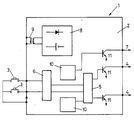
- the device (1) consists of a printed circuit (2) which includes a set of pushbuttons (3) by means of which the valves controlling the flow of gas to the burner (not shown for the appliance for household use), are activated.
- the circuit is equipped with a selector (5), so that by means of a trigger (6), a single valve may be selected for use with the corresponding supply.
- the supply source (8) can be used with a storage cell, and can also be connected to the circuit by an isolation transformer (9).
- Both the isolation transformer and the thermocouples (4) together with the spark lighter (7), are controlled by means of timers (10), and in both cases operate on transistors (11).
Landscapes
- Engineering & Computer Science (AREA)
- Chemical & Material Sciences (AREA)
- Combustion & Propulsion (AREA)
- Mechanical Engineering (AREA)
- General Engineering & Computer Science (AREA)
- Control Of Combustion (AREA)
- Feeding And Controlling Fuel (AREA)
Claims (4)
- Un appareil au gaz à dispositif d'allumage instantané (1), avec allumeur à étincelle (7), comprenant au moins un brûleur et au moins un groupe magnétique de soupapes de sécurité et de thermocouples (4) qui seront chauffés par les flammes du ou des brûleurs, afin de permettre le passage du gaz aux brûleuts une fois que ceux-ci seront chauds; une source d'alimentation électrique (8) avec une batterie pour fournir un courant électrique auxiliaire au dispositif d'allumage instantané (1) et au groupe magnétique de soupapes de sécurité; un transformateur d'isolement pour alimenter la source d'alimentation électrique (8), caracterisé par un circuit électrique imprimé (2) avec des sorties et un temporisateur (10) pour l'alimentation et la programmation de l'allumeur à étincelles (7) et le courant auxiliaire au groupe magnétique de soupapes de sécurité et aux thermocouples (4), ce courant auxiliaire étant remplacé par le courant électrique produit par ces derniers une fois portés à température par la flamme, à l'aide d'un déclencheur (6) et d'un sélecteur (5) contrôlant le dispositif d'allumage instantané (1) afin de permettre, le cas échéant, l'alimentation en gaz d'une seule soupape de sécurité à la fois, pour empêcher l'activation simultanée de plus de soupapes de sécurité, et également caractérisé par le fait que la soupape de sécurité se ferme lorsque la température du thermocouple correspondant diminue jusqu'au tiers de l'énergie du courant électrique produit.
- Un appareil au gaz selon revendication 1, caractérisé par le fait qu'il permet l'alimentation en courant électrique par l'intervention du temporisateur (10), de sorte que la durée du courant auxiliaire soit supérieure à celle du fonctionnement de l'allumeur à étincelles (7).
- Un appareil au gaz selon revendication 1, caractérisé par le fait que le dispositif d'allumage (1) comprend un bouton-poussoir (3) permettant l'alimentation électrique du dispositif (3) et par le fait qu'en appuyant sur le bouton-poussoir (3) pour fournir de l'électricité au système d'allumage, l'existence d'une flamme est détectée par ionisation, l'allumeur à étincelles cesse de fonctionner et le temporisateur (10) qui fournit l'énergie électrique auxiliaire au thermocouple continue à fonctionner prndant environ six secondes supplémentaires.
- Un appareil au gaz selon revendication 3, caractérisé par le fait qu'une fois que le thermocouple (4) a été porté à température, l'activation du bouton-poussoir (3) met hors-tension le circuit électrique imprimé (2), qui ainsi ne consomme pas d'énergie.
Applications Claiming Priority (2)
| Application Number | Priority Date | Filing Date | Title |
|---|---|---|---|
| ES9001218 | 1990-04-27 | ||
| ES9001218A ES2021531A6 (es) | 1990-04-27 | 1990-04-27 | Perfeccionamientos en dispositivos de encendido instantaneo en valvulas de seguridad incorporadas utilizados en aparatos a gas. |
Publications (2)
| Publication Number | Publication Date |
|---|---|
| EP0454613A1 EP0454613A1 (fr) | 1991-10-30 |
| EP0454613B1 true EP0454613B1 (fr) | 1995-06-28 |
Family
ID=8267108
Family Applications (1)
| Application Number | Title | Priority Date | Filing Date |
|---|---|---|---|
| EP91500040A Expired - Lifetime EP0454613B1 (fr) | 1990-04-27 | 1991-04-26 | Appareil à gaz |
Country Status (5)
| Country | Link |
|---|---|
| EP (1) | EP0454613B1 (fr) |
| DE (1) | DE69110746T2 (fr) |
| DK (1) | DK0454613T3 (fr) |
| ES (1) | ES2021531A6 (fr) |
| PT (1) | PT97506A (fr) |
Families Citing this family (4)
| Publication number | Priority date | Publication date | Assignee | Title |
|---|---|---|---|---|
| FR2721097A1 (fr) * | 1994-06-10 | 1995-12-15 | Cepem | Dispositif de sécurité pour un appareil de combustion à gaz. |
| US5425631A (en) * | 1994-08-11 | 1995-06-20 | Eaton Corporation | Controlling a gaseous fuel burner and control valve therefor |
| FR2761459B1 (fr) * | 1997-03-28 | 1999-06-18 | Gaz De France | Systeme de securite pour bruleurs d'appareil de cuisson |
| US11098898B2 (en) * | 2018-09-28 | 2021-08-24 | Emerson Electric Co. | Automatic pilot lighting systems |
Family Cites Families (2)
| Publication number | Priority date | Publication date | Assignee | Title |
|---|---|---|---|---|
| US3544247A (en) * | 1968-11-25 | 1970-12-01 | Honeywell Inc | Fuel burner power failure bridge |
| DE1946588B2 (de) * | 1969-09-15 | 1971-01-07 | Mayer & Wonisch | Elektrische Zuendsicherung fuer gasbeheizte Haushaltsgeraete od.dgl. |
-
1990
- 1990-04-27 ES ES9001218A patent/ES2021531A6/es not_active Expired - Lifetime
-
1991
- 1991-04-26 EP EP91500040A patent/EP0454613B1/fr not_active Expired - Lifetime
- 1991-04-26 PT PT97506A patent/PT97506A/pt not_active Application Discontinuation
- 1991-04-26 DE DE69110746T patent/DE69110746T2/de not_active Expired - Fee Related
- 1991-04-26 DK DK91500040.0T patent/DK0454613T3/da active
Also Published As
| Publication number | Publication date |
|---|---|
| DE69110746T2 (de) | 1996-02-08 |
| PT97506A (pt) | 1993-05-31 |
| ES2021531A6 (es) | 1991-11-01 |
| EP0454613A1 (fr) | 1991-10-30 |
| DK0454613T3 (da) | 1995-11-13 |
| DE69110746D1 (de) | 1995-08-03 |
Similar Documents
| Publication | Publication Date | Title |
|---|---|---|
| US5674065A (en) | Apparatus for controlling the supply of gas to and heat from unvented gas heating appliances | |
| US7044729B2 (en) | Gas burner control for a bake oven | |
| US6698417B2 (en) | Device for obtaining rapid ignition of a cooking hob gas burner fed via a gas pipe provided with a solenoid safety valve | |
| US4529373A (en) | Burner safety ignition system allowing for electrical and manual operation | |
| EP0454613B1 (fr) | Appareil à gaz | |
| AU2004217797B2 (en) | Gas regulating fitting | |
| CA2165350C (fr) | Appareil de reglage automatique du fonctionnement d'un bruleur en general | |
| US8668490B2 (en) | Method and arrangement for igniting a gas flow | |
| GB2034020A (en) | Automatic Gas Burning Apparatus | |
| US3434788A (en) | Burner control system | |
| JPH0113254Y2 (fr) | ||
| JP2731858B2 (ja) | ガス機器の安全装置 | |
| JPS5819939B2 (ja) | バ−ナ用安全点火装置 | |
| GB2351341A (en) | Valve assembly for use in controlling the ignition of a gas burner | |
| KR920009087B1 (ko) | 연소제어장치 | |
| KR920008878B1 (ko) | 급탕기의 연소제어장치 | |
| JP2500301B2 (ja) | 燃焼装置の制御装置 | |
| JP3539040B2 (ja) | 燃焼装置 | |
| KR910002741B1 (ko) | 연소제어장치 | |
| JPH0136046Y2 (fr) | ||
| GB2317684A (en) | An ignition system of a gas heating appliance | |
| JPH0223970Y2 (fr) | ||
| JP3072265B2 (ja) | ガス器具 | |
| JPH0355430A (ja) | 電磁安全弁の吸着操作用ソレノイド制御装置 | |
| JPS6441720A (en) | Hot water boiler |
Legal Events
| Date | Code | Title | Description |
|---|---|---|---|
| PUAI | Public reference made under article 153(3) epc to a published international application that has entered the european phase |
Free format text: ORIGINAL CODE: 0009012 |
|
| AK | Designated contracting states |
Kind code of ref document: A1 Designated state(s): AT BE CH DE DK FR GB GR IT LI LU NL SE |
|
| 17P | Request for examination filed |
Effective date: 19920609 |
|
| 17Q | First examination report despatched |
Effective date: 19920925 |
|
| RBV | Designated contracting states (corrected) |
Designated state(s): BE DE DK FR GB IT NL |
|
| GRAA | (expected) grant |
Free format text: ORIGINAL CODE: 0009210 |
|
| AK | Designated contracting states |
Kind code of ref document: B1 Designated state(s): BE DE DK FR GB IT NL |
|
| REF | Corresponds to: |
Ref document number: 69110746 Country of ref document: DE Date of ref document: 19950803 |
|
| ITF | It: translation for a ep patent filed | ||
| ET | Fr: translation filed | ||
| REG | Reference to a national code |
Ref country code: DK Ref legal event code: T3 |
|
| PLBI | Opposition filed |
Free format text: ORIGINAL CODE: 0009260 |
|
| PLAV | Examination of admissibility of opposition |
Free format text: ORIGINAL CODE: EPIDOS OPEX |
|
| PLBQ | Unpublished change to opponent data |
Free format text: ORIGINAL CODE: EPIDOS OPPO |
|
| 26 | Opposition filed |
Opponent name: BOSCH-SIEMENS HAUSGERAETE GMBH Effective date: 19960328 |
|
| PLAV | Examination of admissibility of opposition |
Free format text: ORIGINAL CODE: EPIDOS OPEX |
|
| PLBF | Reply of patent proprietor to notice(s) of opposition |
Free format text: ORIGINAL CODE: EPIDOS OBSO |
|
| NLR1 | Nl: opposition has been filed with the epo |
Opponent name: BOSCH-SIEMENS HAUSGERAETE GMBH |
|
| PLBF | Reply of patent proprietor to notice(s) of opposition |
Free format text: ORIGINAL CODE: EPIDOS OBSO |
|
| PLBF | Reply of patent proprietor to notice(s) of opposition |
Free format text: ORIGINAL CODE: EPIDOS OBSO |
|
| PLBO | Opposition rejected |
Free format text: ORIGINAL CODE: EPIDOS REJO |
|
| APAC | Appeal dossier modified |
Free format text: ORIGINAL CODE: EPIDOS NOAPO |
|
| APAE | Appeal reference modified |
Free format text: ORIGINAL CODE: EPIDOS REFNO |
|
| APAC | Appeal dossier modified |
Free format text: ORIGINAL CODE: EPIDOS NOAPO |
|
| APAC | Appeal dossier modified |
Free format text: ORIGINAL CODE: EPIDOS NOAPO |
|
| PLBN | Opposition rejected |
Free format text: ORIGINAL CODE: 0009273 |
|
| STAA | Information on the status of an ep patent application or granted ep patent |
Free format text: STATUS: OPPOSITION REJECTED |
|
| PGFP | Annual fee paid to national office [announced via postgrant information from national office to epo] |
Ref country code: DK Payment date: 20010425 Year of fee payment: 11 |
|
| PGFP | Annual fee paid to national office [announced via postgrant information from national office to epo] |
Ref country code: GB Payment date: 20010426 Year of fee payment: 11 Ref country code: FR Payment date: 20010426 Year of fee payment: 11 |
|
| PGFP | Annual fee paid to national office [announced via postgrant information from national office to epo] |
Ref country code: BE Payment date: 20010427 Year of fee payment: 11 |
|
| PGFP | Annual fee paid to national office [announced via postgrant information from national office to epo] |
Ref country code: NL Payment date: 20010430 Year of fee payment: 11 |
|
| 27O | Opposition rejected |
Effective date: 20001214 |
|
| PGFP | Annual fee paid to national office [announced via postgrant information from national office to epo] |
Ref country code: DE Payment date: 20010615 Year of fee payment: 11 |
|
| NLR2 | Nl: decision of opposition | ||
| REG | Reference to a national code |
Ref country code: GB Ref legal event code: IF02 |
|
| PG25 | Lapsed in a contracting state [announced via postgrant information from national office to epo] |
Ref country code: GB Free format text: LAPSE BECAUSE OF NON-PAYMENT OF DUE FEES Effective date: 20020426 |
|
| PG25 | Lapsed in a contracting state [announced via postgrant information from national office to epo] |
Ref country code: DK Free format text: LAPSE BECAUSE OF NON-PAYMENT OF DUE FEES Effective date: 20020430 Ref country code: BE Free format text: LAPSE BECAUSE OF NON-PAYMENT OF DUE FEES Effective date: 20020430 |
|
| PG25 | Lapsed in a contracting state [announced via postgrant information from national office to epo] |
Ref country code: NL Free format text: LAPSE BECAUSE OF NON-PAYMENT OF DUE FEES Effective date: 20021101 Ref country code: DE Free format text: LAPSE BECAUSE OF NON-PAYMENT OF DUE FEES Effective date: 20021101 |
|
| REG | Reference to a national code |
Ref country code: DK Ref legal event code: EBP |
|
| GBPC | Gb: european patent ceased through non-payment of renewal fee |
Effective date: 20020426 |
|
| PG25 | Lapsed in a contracting state [announced via postgrant information from national office to epo] |
Ref country code: FR Free format text: LAPSE BECAUSE OF NON-PAYMENT OF DUE FEES Effective date: 20021231 |
|
| NLV4 | Nl: lapsed or anulled due to non-payment of the annual fee |
Effective date: 20021101 |
|
| REG | Reference to a national code |
Ref country code: FR Ref legal event code: ST |
|
| PG25 | Lapsed in a contracting state [announced via postgrant information from national office to epo] |
Ref country code: IT Free format text: LAPSE BECAUSE OF NON-PAYMENT OF DUE FEES;WARNING: LAPSES OF ITALIAN PATENTS WITH EFFECTIVE DATE BEFORE 2007 MAY HAVE OCCURRED AT ANY TIME BEFORE 2007. THE CORRECT EFFECTIVE DATE MAY BE DIFFERENT FROM THE ONE RECORDED. Effective date: 20050426 |
|
| APAH | Appeal reference modified |
Free format text: ORIGINAL CODE: EPIDOSCREFNO |