EP0455431B1 - Flüssigkeitsspender mit Abgabevorrichtung zur Erzeugung eines Ansaugluftstroms - Google Patents
Flüssigkeitsspender mit Abgabevorrichtung zur Erzeugung eines Ansaugluftstroms Download PDFInfo
- Publication number
- EP0455431B1 EP0455431B1 EP91303793A EP91303793A EP0455431B1 EP 0455431 B1 EP0455431 B1 EP 0455431B1 EP 91303793 A EP91303793 A EP 91303793A EP 91303793 A EP91303793 A EP 91303793A EP 0455431 B1 EP0455431 B1 EP 0455431B1
- Authority
- EP
- European Patent Office
- Prior art keywords
- liquid
- container
- discharge
- nipple
- opening
- Prior art date
- Legal status (The legal status is an assumption and is not a legal conclusion. Google has not performed a legal analysis and makes no representation as to the accuracy of the status listed.)
- Expired - Lifetime
Links
Images


Classifications
-
- A—HUMAN NECESSITIES
- A47—FURNITURE; DOMESTIC ARTICLES OR APPLIANCES; COFFEE MILLS; SPICE MILLS; SUCTION CLEANERS IN GENERAL
- A47K—SANITARY EQUIPMENT; ACCESSORIES THEREFOR, e.g. TOILET ACCESSORIES
- A47K5/00—Holders or dispensers for soap, toothpaste or the like
- A47K5/06—Dispensers for soap
- A47K5/12—Dispensers for soap for liquid or pasty soap
- A47K5/1202—Dispensers for soap for liquid or pasty soap dispensing dosed volume
- A47K5/1208—Dispensers for soap for liquid or pasty soap dispensing dosed volume by means of a flexible dispensing chamber
- A47K5/1209—Dispensers for soap for liquid or pasty soap dispensing dosed volume by means of a flexible dispensing chamber with chamber in the form of a cylindrical tube
-
- B—PERFORMING OPERATIONS; TRANSPORTING
- B67—OPENING, CLOSING OR CLEANING BOTTLES, JARS OR SIMILAR CONTAINERS; LIQUID HANDLING
- B67D—DISPENSING, DELIVERING OR TRANSFERRING LIQUIDS, NOT OTHERWISE PROVIDED FOR
- B67D1/00—Apparatus or devices for dispensing beverages on draught
- B67D1/0042—Details of specific parts of the dispensers
- B67D1/0078—Ingredient cartridges
- B67D1/0079—Ingredient cartridges having their own dispensing means
Definitions
- the present invention relates to apparatus for dispensing liquid, normally in discrete small quantities or charges.
- the invention has particular application to the dispensing of liquid from replaceable cartridges which may contain grit for scouring purposes.
- U.S. patent no. 4,108,363 includes a flexible pump bowl which receives soap from a container through a diaphragm-type check valve. When the bowl is compressed it closes the check valve and forces the soap in the bowl out through a passageway to a discharge outlet.
- This structure is relatively complex and is not well suited to modern distribution networks which require field maintenance by unskilled laborers, nor is it suited to the dispensing of soap containing grit, since the grit tends to clog the passageways in the device thereby increasing maintenance problems.
- U.S. patent no. 1,326,880 the dispenser ejecting soap directly from a slit in the pump nipple.
- This dispenser utilizes a custom-made check valve stopper in the soap container outlet, and depends on distortion of the slit in the nipple for dispensing of soap therefrom.
- the nipple is compressed in the direction of the slit. This has the disadvantage that the slit can be opened permitting soap to drip therefrom before pressure in the nipple has been raised sufficiently to close the check valve.
- U.S. patent no. 4,646,945 issued to Robert L. Steiner et al, there is disclosed a vented discharge assembly for a liquid soap dispenser including a valved vent opening separate from the outlet opening for the liquid soap for providing a vent path through the discharge assembly while effectively preventing discharge of liquid soap through the vent path.
- a valved vent opening separate from the outlet opening for the liquid soap for providing a vent path through the discharge assembly while effectively preventing discharge of liquid soap through the vent path.
- Another vented discharge assembly for a liquid soap dispenser includes a semipermeable filter mounted between the discharge assembly and the soap container to introduce air into the soap container immediately upon withdrawal of soap from the container to permit rapid operation of the discharge assembly.
- the filter comprises a disc-shaped semi-permeable membrane installed in the air passageway which is offset radially from the liquid soap outlet opening.
- the air passageway has a relatively small cross section making it susceptible to becoming blocked as the result of soap drying on the filter membrane.
- anti-bootleg devices have been included in the dispenser mechanism to prevent the use of unauthorized cartridges therein.
- soap dispensers including anti-bootleg devices are disclosed, for instance, in Steiner et al U.S. patent nos. 4,391,309 and 4,429,812.
- these prior art soap dispensers employ a dispensing pump mechanism which is integral with the housing which defines a reservoir from which soap is drawn in use.
- the cartridge is adapted for mounting on the housing and supplies soap to the reservoir by gravity.
- the anti-bootleg mechanism comprises a plurality of keys located in the inlet opening of the reservoir which prevent proper seating of unauthorized cartridges.
- Another object of the invention is the provision of a discharge assembly for a liquid dispenser which is suitable for dispensing full discrete charges in rapid succession.
- a further object of the invention is the provision of a discharge assembly for a liquid dispenser which is of simple and economical construction, and is characterized by ease of assembly.
- Still another object of the invention is the provision of a discharge assembly for a liquid dispenser including a venting arrangement which ensures full dosage for rapid repeat operation of the discharge assembly.
- Yet another object of the invention is to provide a discharge assembly for a liquid dispenser including a venting arrangement which provides a more positive air flow condition than was provided by prior art venting arrangements.
- liquid dispenser as claimed in the ensuing claim 1, the preamble of claim 1 being already known from document US-A-4646945.
- the liquid dispensing system 20 comprises a dispenser 25 adapted to be mounted on an associated support surface 21, such as on a wall 22 and, more particularly, in a recess 23 therein (see FIGS. 3 and 4), and a disposable liquid cartridge 26 which contains a supply of liquid and is removably mountable on the dispenser 25 for cooperation therewith to control the dispensing of liquid therefrom.
- the liquid may be liquid soap, alcohol, gel, suntan oil, or any material that flows.
- the liquid cartridge includes a discharge assembly which allows mounting of the cartridge on the dispenser without specific orientation therebetween.
- the discharge assembly includes a filter which prevents contaminated air from entering the cartridge, which filter allows a more positive air flow condition than is provided by known liquid dispensing systems of the type which are vented through their outlet opening.
- the liquid dispenser includes an anti-bootleg structure for preventing unauthorized cartridges from being used with the dispenser, the anti-bootleg structure including an anti-bootleg device 28 secured to the dispenser and a cooperating surface configuration 29 for the cartridge neck, as will be described.
- the cartridge 26 is inexpensively manufactured so as to be disposable.
- the dispenser 25 includes a housing 30, which is preferably of unitary, one-piece construction and may be formed of molded plastic.
- the housing 30 is similar to the housing disclosed in United States patent no. 4,673,109, which is assigned to Steiner Corporation.
- the housing 30 includes a flat rectangular base wall 31 and an upstanding rectangular mounting wall 32 integral with the base wall 31 at the rear edge thereof and disposed substantially perpendicular thereto.
- the mounting wall 32 may have fastener holes 33 therethrough for receiving associated fasteners (not shown), securely to mount the housing 30 on the associated support surface 21.
- the housing 30 and cartridge 26 define mating edge surfaces providing a retaining system like that for the dispenser and cartridge illustrated in the referenced U.S. patent no. 4,673,109.
- a continuous peripheral flange 34 integral with the base wall 31 and extending upwardly therefrom along the front and side edges thereof, is a continuous peripheral flange 34, having a stepped down portion 34a on the front edge.
- Side flanges 35 are respectively integral with the side edges of the mounting wall 32 and project forwardly therefrom to join the peripheral flange 34.
- the cartridge 26 includes a liquid container 90 and a liquid discharge assembly 120 which is described in detail hereinbelow.
- the liquid container 90 is a generally box-like container, which may be formed of a suitable plastic material.
- the container 90 is generally in the form of a rectangular parallelepiped having a top wall 92, a bottom wall 93, a front wall 94, a rear wall 95 and a pair of opposed side walls 96.
- the front wall 94 and the side walls 96 are set back or recessed along their lower edges adjacent to their junction with the bottom wall 93 to define a support shoulder 97.
- the top wall 92 projects rearwardly a slight distance beyond the rear wall 95 to form an overhang which defines a stop flange 98.
- the lower portions of the grooves 100 are cut away, as at 101, so as to define lugs 102 adjacent to the upper ends of the grooves 100.
- the cartridge outer surfaces are all dimensioned so that when the cartridge 26 is in its use position on the dispenser the outer surfaces of the front wall and the side walls are, respectively, substantially coplanar with corresponding portions of the housing so as to present an attractive, smooth outward appearance.
- the retaining system formed by rails 36 and grooves 100 prevent forward tilting of the cartridge relative to the dispenser.
- a pair of laterally spaced-apart, upstanding support plates 37 integral with the base wall 31 and with the mounting wall 32 and substantially perpendicular to each are a pair of laterally spaced-apart, upstanding support plates 37, respectively provided with laterally aligned bearing notches 38 in the upper edges thereof (see FIG. 3).
- Formed in the base wall 31 is an elongated, generally rectangular opening 39 (FIGS. 3 and 4) which extends laterally between the support plates 37, the opening 39 having a rearwardly extending rectangular arm 39a and having an arcuate forward end.
- a receptacle 40 Integral with the housing 30 is a receptacle 40 having a peripheral wall 41 which lines the forward portion of the opening 39, the peripheral wall 41 having an arcuate front end and parallel side portions, which side portions are respectively parallel to the support plates 37 and are integral with the inner surfaces thereof at the front ends thereof.
- the peripheral wall 41 projects above and below the base wall 31 and is closed at its lower end by a bottom wall 42 which is disposed substantially parallel to the base wall 31.
- the bottom wall 42 has a circular opening 43 therein adjacent to the forward end thereof, and a generally T-shaped slot 44 therethrough (FIG. 3) just rearwardly of the circular opening 43.
- Respectively formed in the side portions of the peripheral wall 41 below the base wall 31 are two laterally aligned circular pivot openings 45 (FIG. 18).
- a stop web 48 laterally spans the side portions of the peripheral wall 41, extending a slight distance above and below the base wall 31, the web 48 having a rectangular notch 48a in the lower edge thereof and a forwardly directed ledge portion 48b near its upper end.
- a rectangular stop web 49 is formed integrally with and extends upwardly from the base wall 31.
- Web 49 is disposed substantially parallel to the stop web 48 and laterally spans the peripheral wall 41 near its arcuate front end. The upper edge of the stop web and the upper surface of the ledge portion 48b lie substantially in a common horizonal plane.
- Web 49 has a rearwardly directed boss 49a which is semi-cylindrical in shape and extends substantially the width of the web 49.
- the dispenser 25 also includes an actuator assembly 50 which is removably mounted in the housing 30.
- the actuator assembly 50 includes a handle 51 comprising a rectangular plate 52 provided at its upper end with an inclined portion 53, which is in turn provided at its distal end with laterally outwardly extending cylindrical pivot lugs 54.
- the pivot lugs 54 are respectively received in the bearing notches 38 for pivotally supporting the handle 51 which extends through opening 39 in the housing bottom, for movement between actuating and retracted positions.
- the plate 52 has a width slightly less than the width of the opening 39, so that the base wall 31 at the rear end of the opening 39 and the rear flanges 46 of the receptacle 40 provide rear and front stops to limit the pivotal movement of the handle 51.
- a rectangular recess 55 Formed in the front surface of the plate 52 is a rectangular recess 55, near the lower end of which is formed a rectangular slot 56 which extends through the thickness of the plate 52 midway between the side edges thereof and in position so as to be disposed below the base wall 31 when the handle 51 is disposed in its mounted condition in the housing 30.
- the actuator assembly 50 also includes a bias unit 60 which comprises a latch member 61 and a bias leaf 70.
- the latch member 61 is generally in the form of a clevis having a pair of parallel, spaced-apart arms 62, respectively provided with angled feet 63, at the lower ends thereof.
- the feet 63 are respectively provided with laterally outwardly extending circular cylindrical pivot lugs 64, each having a substantially square key socket 65 formed in the outer end thereof, which may extend laterally completely therethrough.
- Each of the feet 63 is also provided on its inner surface with a bearing boss 66.
- the arms 62 are interconnected at their upper ends by a bight portion 67 provided with a forwardly extending latch flange 68 having a part frustoconical cam surface 69 thereon which locks the cartridge in place on the dispenser.
- the latch member 61 is dimensioned to fit within the receptacle 40 with the arms 62 respectively disposed along the inner surfaces of the side portions of the peripheral wall 41.
- the arms 62 are resiliently deflected together to permit the pivot lugs 64 to clear the inner surfaces of the peripheral wall 41, and then the latch member 61 is lowered into the receptacle 40 until the pivot lugs 64 respectively snap out into the pivot openings 45 (FIG. 18 ), pivotally to mount the latch member 61.
- the length of the arms 62 is such that when the latch member 61 is in this mounted condition, the latch flange 68 is disposed a predetermined distance above the upper end of the receptacle 40.
- the bias leaf 70 comprises a thin, flat, rectangular band which is formed of a suitable flexible and resilient material, such as a suitable plastics material. One end of the bias leaf 70 is fixedly secured to the rear surface of the bight portion 67 of the latch member 61 by suitable means (not shown).
- the bias leaf 70 is fabricated with predetermined curvature therein, and is provided with a curved tip 72 at its distal end which has a rectangular slot 73 therethrough.
- a key 75 having a lug 76 thereon which is disposed for mating engagement in one of the key sockets 65 to effect manual rotation of the latch member 61 about the axis of the pivot lugs 64 for releasing the cartridge when spent, allowing replacement with a full cartridge.
- the actuator assembly 50 also includes a plunger 80, which is generally in the shape of a rectangular, box-like, open-top frame. More particularly, referring to FIGS. 2-7, the plunger 80 includes a pair of parallel rectangular side walls 81 interconnected, respectively, at the forward and rearward ends thereof by a front bearing wall 82 and a rear wall 83.
- the front bearing wall 82 curves forwardly and downwardly from its upper edge to a point of maximum forward extension defining cam surface 82a which is approximately one third the distance from its upper edge to its lower edge, the front bearing wall portion 82b extending linearly downwardly and rearwardly from its point of maximum forward extension to its bottom edge.
- the front bearing wall 82 defines a generally arcuate cam surface 82a which is offset upwardly of the horizontal center line of the plunger 80 and following surface 82b.
- the arcuate cam surface 82a is aligned with and in opposing relation to the boss portion 49a on web 49.
- the rear wall 83 is provided with a forwardly extending pin 85 which is received in slot 73 of bias leaf 70. Integral with the outer or rear surface of the rear wall 83 is a rearwardly extending rectangular positioning lug 86 which is received in slot 56 in the handle 51.
- the side walls 81 are interconnected at the lower edges thereof, intermediate the front and rear ends thereof by a rectangular bottom web 87.
- the plunger 80 is dimensioned so that it can fit between the notches 47 of the receptacle rear flanges 46, through the notch 48a in the stop web 48 and between the bearing bosses 66 of latch member 61 for reciprocating siding movement forwardly and rearwardly along the bottom wall 42 of the receptacle 40 between pumping and release positions in response to operation and release of the handle 51.
- the parts of the actuator assembly 50 viz., the handle 51, the bias unit 60 and the plunger 80, can be quickly and easily assembled with the housing 30 without the use of tools and, when thus assembled, will cooperate with each other and with the housing 30 to retain the actuator assembly 50 in the housing 30 and prevent accidental removal thereof.
- the manner in which the actuator assembly 50 is assembled in the housing is described in detail in the referenced U.S. patent no. 4,673,109.
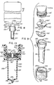
- the liquid cartridge 26 includes a liquid container 90 and a discharge assembly 120. Integral with the liquid container 90 at the distal end thereof is a cylindrical nozzle or neck 113 which projects downwardly from the bottom wall and which includes a thin wall portion 113a which defines an outlet opening for the container 90.
- the neck portion 113 of the liquid container 90 is externally threaded as at 114 and has an end surface 115, as seen in FIG. 8.
- the discharge assembly 120 includes an elongated, generally circular nipple 121 and a check valve assembly 122.
- the discharge assembly 120 is mounted on the threaded neck portion of the liquid container and maintained thereon by a retaining cap 123.
- the nipple 121 is formed of a suitable flexible resilient material, such as rubber.
- the nipple 121 has a main body portion defined by a cylindrical side wall 130 which is provided at its proximal end with a radially outwardly extending flange 131 and an annular upstanding wall 132 defining an inlet chamber 133 for the discharge assembly.
- the hollow main body portion defines a discharge chamber 135 for the discharge assembly.
- the side wall 130 is provided at its distal end with a pair of radially inwardly sloping concave walls 136 which cooperate to form a flat, narrow duckbill-shaped tip 137 at the distal end of the nipple, closing the discharge chamber 135.
- elongated slot 138 Formed in the tip 137 and extending longitudinally thereof, substantially diametrically of the nipple 130, is an elongated slot 138 which in length is approximately one-half the diameter of the nipple.
- the upper edge of the slot 138 terminates in an elongated discharge slit 139, which is normally held closed by the resilient biased nipple 130.
- the slit 139 extends along only a portion, approximately one-third, of the length of the duck-bill tip 137.
- Non-slitted top portions 137a on each side of the slit 139 assist in maintaining the slit 139 closed in the absence of release pressure in the nipple discharge chamber 135.
- the slit 139 is recessed relative to the distal tip of the nipple by an amount corresponding to the depth of the slot 138.
- the ratio of the length "L" of the main body portion and tip of the nipple to the average diameter "D" is about 3 to 1.
- the check valve assembly 122 includes a valve diaphragm disc 140 and a filter member 142.
- the valve diaphragm 140 is a thin, flat circular membrane or diaphragm dimensioned to fit within the inlet chamber or well 133 defined by the upstanding annular wall 132 of the nipple 121 with its lower peripheral edge 140a supported by a ledge or shoulder portion 131a defined by the inner upper surface of flange 131.
- the diaphragm is made of a suitable flexible material which is impermeable to liquid.
- the diaphragm has a straight-line check valve slit 141 formed therein centrally thereof and extending substantially diametrically.
- the filter member 142 has a cylindrical main body portion 143 with an annular flange 144 extending outward radially at its upper surface 145.
- the filter member 142 has an axial bore 146 formed therethrough centrally thereof from its upper surface 145 to its lower surface 147.
- the outer diameter of the main body portion 143 at its distal end surface 147 corresponds to the outer diameter of the valve diaphragm, which diameters are slightly less than the inner diameter of the well 133 defined by the annular wall 132 of the nipple.
- the outer diameter of the top surface 145 including the flange 144 is approximately the same as the outer diameter of annular wall portion 132 of nipple 121.
- the filter member 142 may be made from any suitable material which permits air to pass therethrough but which does not permit liquid to flow therethrough, such as a hydrophobic cell structured thermoplastic. Material particularly suitable for this purpose is commercially available. Representative thermoplastics are nylon, polyesters, polypropylene and teflon, polyurethane, ABS and the like, produced for instance by Filtertek, Inc. of Hebron, Illinois.
- the filter element is a molded porous plastic material having a pore size in the range of about 0.2 microns to about 40 microns.
- valve diaphragm 140 is positioned in the well 133 with its peripheral edge 140a supported on the ledge portion 131a.
- the filter member 142 is positioned in the well 133 with its lower surface 147 engaging the upper surface of the valve diaphragm over substantially its entire extent and with the under surface of its flange engaging the top edge surface of the annular wall 132.
- the filter member 142 substantially fills the entire inlet chamber or well 133 of the nipple between the outlet of the container and the valve diaphragm 140.
- the filter presents a large surface area to the outlet of the liquid container 90 and is located in contact with the liquid, the filter material is continually wetted by the liquid and thus will not become clogged by dried or hardened liquid.
- the aperture 146 through the filter member 142 is aligned with the valve slit 141 in the valve diaphragm by virtue of its being located axially of the filter member, and defines a passageway for liquid to the valve disc.
- the retaining cap 123 is in the form of a cylindrical collar which has a central aperture 151 of a size through which the main body portion of the nipple 121 may grass.
- the retaining cap has internal threads 152 between its upper edge surface 153 and its lower edge surface 154 which are dimensioned loosely to engage the external threads 114 on the liquid container neck 113 and with the liquid container lower edge 115 engaging the upper surface 145 of the filter member 142.
- the retaining cap 123 serves to removably mount the discharge assembly 120 on the neck of the container 112. Because the retaining ring 123 removably secures the discharge assembly to the container 90, it is possible to recover discharge assemblies from spent cartridges, if desired.
- the discharge assembly controls the flow of liquid between the outlet opening of the container 90 and the inlet opening or inlet chamber 133 of the nipple 121.
- An air path is thereby established, as best seen by the arrows in FIG. 10, between outside the container 90 and the inside thereof, which air path flows between the neck 13 of the liquid container 90 and the upper edge 153 of the cylindrical collar 123 through and along the threads 114 and 152 and thereafter through the space 160 and through the filter member 142 into the liquid container 90.
- the check valve assembly 122 is disposed for controlling the flow of liquid between the outlet opening of the container 90 and the inlet opening or inlet chamber 133 of the nipple 121.
- the cartridge 26 in mounting the cartridge 26 on the dispenser 25, it is placed over the dispenser 25 with the neck 113 disposed downwardly.
- the cartridge 26 is slid down along the mounting wall 32 of the housing 30, with the retaining rails 36 being respectively recessed in the longitudinal grooves 100.
- the nipple 121 extends downwardly into the receptacle 40 between stop webs 48 and 49 and in coaxial alignment with the circular opening 43 in the bottom wall 42.
- the latch flange 68 of latch member 61 projects forwardly beyond stop web 48, engaging the top surface edge 153 of the cap 123 so as to obstruct the path of the neck 112, latching the cartridge in place.
- the lower edge 154 of the retaining cap 123 rests on ledge 48a and on the upper edge 49b of web 49, locating the main body portion 130 of the nipple 121 between the forward cam surface 82a of the plunger 80 and the rearwardly extending boss 49a on the front web 49.
- the operation of the discharge assembly 120 will be explained.
- the atmospheric pressure plus the weight of the liquid in the container on the diaphragm disc 140 near the slit 141 therein will force the check valve slit 141 open, allowing liquid to flow through the check valve slit opening into the discharge chamber 135 in the nipple 121.
- This flow will continue until the discharge chamber 135 is filled, at which time the pressure on the opposite sides of the valve disc 140 will be equalized, thereby allowing the check valve slit 141 to close in an equilibrium condition, as illustrated in FIG. 15.
- the nipple 121 is so constructed that in this normal equilibrium condition, the natural resilient bias of the nipple 121 will hold the discharge slit 139 closed against the weight of the charge of liquid contained in the discharge chamber 135.
- a user places his palm under the nipple 121 and pulls the handle 51 (FIG. 3) forwardly towards its actuating position with his fingers.
- This drives the plunger 80 forwardly of the housing to its pumping position against the force of bias member 70, and into engagement with the nipple 121, compressing it, as shown in FIG. 16, between the cam surface 82a and the boss 49a on forward wall 49, ejecting the charge of liquid therefrom through the discharge outlet 137 of the nipple 121.
- the tip of the cam surface 82a engages the nipple main body portion near its upper end, compressing the nipple near its upper end.
- This reexpansion of the nipple 121 will lower the pressure therein to a pressure below that in the container 90, so as to allow the check valve slit 141 to open under the force of atmospheric pressure and the weight of the liquid in the container.
- a new charge of liquid is drawn from the container 90 (thereby creating lower pressure in container 90) through aperture 146 in the filter member 142 and the check valve opening 141 and the diaphragm disc 140 into the discharge chamber 135 of the nipple 121.
- the rate at which the liquid flows into the nipple 121, and particularly into the discharge chamber 135, is controlled to some extent by the pressure in the liquid container 90.
- the pressure is equalized to normal atmospheric pressure by means of the air path established between the inside of the liquid container 90 and the atmosphere (which path is shown by the arrows in FIG. 10) and flows through the filter member 142 and the inlet chamber 133. Particularly, the air flows downwardly past the upper edge 153 of the retaining cap 123 through and around the mating threads 114, 152 and into the annular space beneath the threads and hence through the filter member 142 to the liquid container outlet, and into the container 90.
- This mechanism permits air to flow into the liquid container 90 while retaining the liquid therein.
- This construction facilitates rapid discharge and charge of the discrete quantities of liquid from the nipple 121 and is an improvement over the previous constructions heretofore mentioned.
- the liquid dispensing system provided in accordance with the present invention includes a discharge assembly and an actuating mechanism therefor which allows mounting of the cartridge on the dispenser without specific orientation of the nipple of the discharge assembly relative to the plunger of the actuating mechanism.
- the discharge mechanism includes a filter element which is constructed and arranged to both define a portion of an air passageway for venting the liquid container through its outlet opening and for providing a passageway for liquid from the container to the discharge nipple, the filter element allowing a more positive air flow condition than is provided by known liquid dispensing systems of the type employing containers vented through their outlet opening.
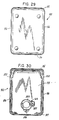
- the dispenser 25 includes an anti-bootleg structure 28 including anti-bootleg device 160 for preventing unauthorized cartridges from being used in the dispenser 25.
- the anti-bootleg device 160 comprises a flat plate-like member 161 generally rectangular in shape and having a central opening 162 therethrough of an irregular shape, complementary with irregular shaped neck portion 164 of the associated container 26 shown in FIGS. 25-30.
- the plate member 161 has a forward edge 165, a rearward edge 166, a left side edge 167 and a right side edge 168.
- the irregular shaped opening 162 includes a generally circular central aperture 162a with a generally rectangular-shaped extension 162b extending toward the left side edge 167 of the plate and an arcuate segment 162c extending toward the forward edge 165 of the plate member.
- the plate member 161 is mounted on the housing 30 (FIG. 18) overlying the well 40 which receives the discharge assembly 120 of the cartridge 26, with the neck of the cartridge 26 extending through the irregular shaped aperture 162 of the plate member 161. It is apparent that only cartridges which have a neck portion configured to pass through the irregular opening 162 in the anti-bootleg device 160 can seat on the dispenser 25 in such a way as to permit the discharge assembly 120 of the cartridge 26 to be operated by actuator mechanism of the dispenser.
- the device 160 has four projections or lugs 171-174 which depend from lower surface 175 of the plate 161, one located near each of the four corners of the plate.
- the housing 30 has four supports or posts 176-179 which are formed integrally with and extend upwardly from the base 42 of the housing 30. Two of the posts 176-177 are located on the left side of the well and the other two posts 178-179 are located on the right side of the well 40. All four posts extend to a height above the upper edge of the well 40 to locate the anti-bootleg device 160 in overlying relation with the well and slightly above the upper edge surface of the well.
- the lugs 171-174 are split at 180 and are dimensioned to be received in apertures 170 through the respective posts 176, 178, 177, and 179, which apertures are stepped outwardly in a direction from top to bottom, defining an inner shoulder 181.
- the lugs may be retained in the apertures 170 by a snap fit, ultrasonic welding or other means to permanently secure the plate 161 to the housing.
- the spacing between lugs 171 and 172 near the forward edge 165 of the plate 161 is less than the spacing between lugs 173 and 174 near the rearward edge 166.
- the spacing between the forwardly located posts 176 and 178 is less than the spacing between the rearwardly located posts 177 and 179 to ensure proper orientation of the plate 161 when it is installed on the housing.
- the liquid container 90 is particularly adapted to be received by the dispenser 25 including the anti-bootleg device 160.
- the neck 113 of the container 90 has a generally cylindrical portion 184 of a diameter corresponding to the diameter of the aperture 162a in the plate 161 and with a generally rectangular boss 185 and an arcuate boss 186 which are complementary to aperture extension portions 162b and 162c, respectively, of the aperture 162 in the anti-bootleg plate 161.
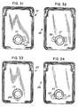
- Various combinations of rectangular and arcuate aperture portions can be used to define many unique irregular shapes for anti-bootleg device 160 and cartridges for use exclusively therewith. Moreover, only the anti-bootleg device 160 need be different, permitting manufacture of a "generic" dispenser unit, adapted by application thereto of a given anti-bootleg device to receive a given cartridge. For example, referring now to Figs. 31-34, there are illustrated four cartridges 191-194 each having a different irregular-shaped neck portion for use with a dispenser having, respectively, one of the four anti-bootleg devices 195-198 illustrated in FIGS. 35-38.
- device 195 has an irregular-shaped opening 201 having two rectangular extension portions 201a and 201b which extend toward its left side edge 167 of the plate member 161.
- Portion 201a which is the same shape and the same location as portion 162b (FIG. 21), is longer than portion 201b.
- the neck 113 of container 191 has complementary shaped rectangular bosses 202 and 203, which are disposed in the neck 113 and dimensioned to pass through the irregular opening 201 in the device 195.
- device 196 has an irregular opening 204 having two generally rectangular extension portions 204a and 204b, which are the same shape as portion 101a and extend, respectively, towards its left side edge 167 and its right side edge 168 rearward of the center line of the plate 161.
- the neck 113 of container 192 has complementary shaped bosses 205 and 206, which are so disposed on the neck 113 and dimensioned to pass through the irregular opening 204 in the device 196.
- device 197 has an irregular shaped opening 207 having an arcuate extension portion 207a which is the same shape and at the same location as portion 162c of device 160 (FIG. 21) and which extends towards its forward edge 165.
- Associated container 193 has a complementary boss 208 on its neck 113 which is disposed to pass through the irregular opening in the device 197.
- device 198 has an irregular-shaped opening 209 having two generally rectangular extension portions 209a and 209b which are the same shape as portion 201b (FIG. 35) and extend, respectively, toward the left side edge 167 and the right side edge 168, but forward of the center line of the plate 161.
- Corresponding container 194 has complementary bosses 211 and 212 on its neck portion 113 which are disposed to pass through the irregular opening 209 in the device 198.
- a liquid dispensing system in which a common dispenser 25 has permanently mounted to it a selected one of a plurality of anti-bootleg devices, overlying the actuator mechanism and upon which an associated cartridge must be mounted.
- the anti-bootleg device has a particularly chosen irregular-shaped opening which will preclude the use of any cartridge except a cartridge having a complementary shaped neck portion.
- the user of unauthorized cartridges in dispensers having the anti-bootleg device of the present invention is prevented because the anti-bootleg device precludes proper seating of the dispensing mechanism of such unauthorized cartridge on the actuator mechanism, whereby the actuator cannot operate the dispenser mechanism, thereby rendering the liquid dispenser inoperable.
Landscapes
- Health & Medical Sciences (AREA)
- Public Health (AREA)
- Containers And Packaging Bodies Having A Special Means To Remove Contents (AREA)
- Closures For Containers (AREA)
- Nozzles (AREA)
- Telephone Function (AREA)
Claims (15)
- Flüssigkeitsspender (25), der folgendes umfaßt: einen nicht entlüfteten Flüssigkeitsbehälter (90) mit nur einer Auslaßöffnung (113), eine mit jener Auslaßöffnung (113) des Flüssigkeitsbehälters in Flüssigkeitsverbindung stehende Abgabevorrichtung (120), wobei jene Abgabevorrichtung (120) ein Abgabemittel aufweist, das eine Abgabekammer (135) zur Aufnahme einer Flüssigkeitsmenge und eine Einlaßkammer (133) zur Einleitung von Flüssigkeit in jene Abgabekammer (135) definiert, und ein Rückschlagventilmittel (122) in jener Einlaßkammer zur Regulierung des Flüssigkeitsstroms von jenem Behälter (90) zu jener Abgabekammer (135), wobei jenes Rückschlagventilmittel ein Ventilglied (140) und ein Element (142) aufweist, das in jener Einlaßkammer (133) befestigt ist und diese im wesentlichen zwischen jenem Ventilglied (140) und jener Auslaßöffnung (113) des Flüssigkeitsbehälters füllt, wobei jenes Element (142) einen Luftdurchgang zur Einleitung von Luft in jenen Flüssigkeits behälter bei Entnahme von Flüssigkeit aus jenem Behälter (90) bildet und jenes Element (142) eine dadurch führende Öffnung (146) aufweist, die einen Durchflußkanal für Flüssigkeit von jener Auslaßöffnung (113) des Behälters zu jenem Ventilglied (140) zur Einleitung in jene Abgabekammer definiert, dadurch gekennzeichnet, daß es sich bei jenem Element (142) um ein halbdurchlässiges Filterelement aus einem Material handelt, das luftdurchlässig und flüssigkeitsundurchlässig ist.
- Flüssigkeitsspender nach Anspruch 1, dadurch gekennzeichnet, daß ein Luftdurchgang jenes Filterelement (142) mit der Außenseite jenes Flüssigkeitsbehälters verbindet.
- Flüssigkeitsspender nach Anspruch 1, gekennzeichnet durch Haltemittel (114, 152), die jene Abgabevorrichtung (120) gegenüber jenem Flüssigkeitsbehälter (90) in Stellung halten und einen Luftdurchgang zu jenem Filterelement (142) zur Verfügung stellen.
- Flüssigkeitsspender nach einem der vorhergehenden Ansprüche, dadurch gekennzeichnet, daß jenes Filterelement (142) allgemein zylindrischer Gestalt ist und einen Außendurchmesser aufweist, der dem Innendurchmesser jener Auslaßöffnung (113) der Patrone entspricht, wobei sich jene Öffnung (146) durch jenes Filterelement (142) in dessen Mitte befindet.
- Flüssigkeitsspender nach einem der vorhergehenden Ansprüche, dadurch gekennzeichnet, daß es sich bei jenem Filterelement (142) um ein geformtes poröses Kunststoffmaterial mit einer Porengröße im Bereich von ca. 0,2 µm bis ca. 40 µm handelt.
- Flüssigkeitsspender nach einem der vorhergehenden Ansprüche, dadurch gekennzeichnet, daß jenes Filterelement (142) aus einem wasserabweisenden, mikroporösen Polypropylen besteht.
- Flüssigkeitsspender nach einem der vorhergehenden Ansprüche, dadurch gekennzeichnet, daß jene Abgabevorrichtung (120) einen länglichen, flexiblen Nippel (121) allgemein zylindrischer Gestalt und in normalerweise entspanntem Zustand aufweist, der jene Abgabekammer (135) definiert und bei dem die Axiallänge (L) jener Abgabekammer ungefähr dreimal seinem Durchmesser (D) entspricht.
- Flüssigkeitsspender nach einem der Ansprüche 1 bis 6, dadurch gekennzeichnet, daß jene Abgabevorrichtung (120) einen jene Abgabekammer (135) definierenden länglichen, flexiblen, elastischen Nippel (121) in normalerweise entspanntem Zustand umfaßt, der erste und zweite Enden mit jener Einlaßkammer an seinem ersten Ende aufweist und an seinem zweiten Ende mit einem normalerweise geschlossenen Abgabeschlitz (139) versehen ist, sowie Haltemittel (114, 152), die jenen Nippel (121) am Behälter (90) befestigen, wobei jene Einlaßkammer (133) in Deckung mit der Auslaßöffnung (113) des Behälters angeordnet ist, wobei jener Nippel (121) in einer im wesentlichen senkrecht zu seiner Längsachse stehenden Richtung seitlich zusammendrückbar ist, die Bewegung jenes Nippels (121) zu seinem zusammengedrückten Zustand den Druck in jener Abgabekammer (135) zum Schließen jenes Rückschlagventilmittels und Ausstoßen von Flüssigkeit aus jenem Abgabeschlitz (139) ansteigen läßt und die Bewegung jenes Nippels (121) zurück zu seinem entspannten Zustand den Druck in jener Abgabekammer (135) zum Schließen jenes Abgabeschlitzes (139) und Öffnen jenes Rückschlagventilmittels, um eine neue Flüssigkeitsmenge in jene Abgabekammer (135) zu saugen, senkt und Durchgang von Luft durch jenes Filterelement (142) Luftdruck in jenem Flüssigkeitsbehälter (90) schnell wieder herstellt, wodurch ein schnelles Wiederauffüllen jener Abgabekammer (135) mit Flüssigkeit und eine schnelle Aktivierung jener Abgabevorrichtung ermöglicht wird.
- Flüssigkeitsspender nach Anspruch 8, dadurch gekennzeichnet, daß jenes Ventilglied eine flache Membran (140) aufweist, die sich quer über jene Einlaßöffnung erstreckt und einen mittig darin ausgebildeten Ventilschlitz (141) hat, wobei jenes Filterelement (142) mit seiner mittig darin ausgebildeten Öffnung (146) in Deckung mit jenem Ventilschlitz (141) angeordnet über jener Membran (140) liegt.
- Flüssigkeitsspender nach Anspruch 8 oder 9, dadurch gekennzeichnet, daß jener Nippel an jenem ersten Ende eine jene Einlaßkammer definierende ringförmige nach oben stehende Wand (132) und am Fuß jener Wand einen Absatz (131a) aufweist, wobei der Umfangsrand jener Membran (140) auf jenem Absatz (131a) gestützt ist und jenes Filterelement (142) im wesentlichen innerhalb jener Einlaßkammer (133) enthalten ist.
- Flüssigkeitsspender nach Anspruch 1, dadurch gekennzeichnet, daß der Flüssigkeitsbehälter und jene Abgabevorrichtung (120) eine auswechselbare Flüssigkeitspatrone umfassen, die abnehmbar an einem Gehäuse (30) jenes Spenders befestigt werden kann, wobei der Flüssigkeitsspender weiterhin einen in jenem Gehäuse befestigten Betätigungsmechanismus (50) und eine in jenem Gehäuse befestigte, über jenem Betätigungsmechanismus liegende Einsetzsperrvorrichtung (160) umfaßt, wobei jene Einsetzsperrvorrichtung eine durch sie führende Öffnung (162) vorbestimmter Konfiguration und jener Flüssigkeitsbehälter (26) einen Halsabschnitt (164) mit einer zu jener Öffnung (162) durch jene Einsetzsperrvorrichtung (160) komplementären Gestalt aufweist, wodurch jener Halsabschnitt (164) durch jene Einsetzsperrvorrichtung geführt werden kann, um jene Patrone an jenem Gehäuse zu befestigen, wobei jene Abgabevorrichtung (120) in funktioneller Beziehung zu jenem Betätigungsmechanismus (50) zum Spenden von Flüssigkeit aus jenem Flüssigkeitsbehälter angeordnet ist und wobei jene Einsetzsperrvorrichtung verhindert, daß Patronen ohne einen Halsabschnitt jener vorbestimmten Konfiguration mit ihrer Abgabevorrichtung in funktioneller Beziehung zu jenem Betätigungsmechanismus (50) angeordnet an jenem Gehäuse (30) befestigt werden können.
- Flüssigkeitsspender nach Anspruch 11, dadurch gekennzeichnet, daß jene Einsetzsperrvorrichtung (160) fest mit jenem Gehäuse verbunden ist.
- Flüssigkeitsspender nach Anspruch 11 oder 12, dadurch gekennzeichnet, daß jene Einsetzsperrvorrichtung (160) ein flaches, plattenartiges Glied (161) und Befestigungsmittel (171-174) aufweist, die jenes plattenartige Glied (161) an jenem Gehäuse (30) in horizontaler Ausrichtung befestigen, wobei jene Abgabevorrichtung (120) beim Befestigen jener Patrone an jenem Spender durch jene Öffnung (162) durch jenes plattenartige Glied (161) hindurchgeführt wird.
- Flüssigkeitsspender nach Anspruch 13, dadurch gekennzeichnet, daß jenes Befestigungsmittel eine Mehrzahl von Vorsprüngen (171-174) an jenem plattenartigen Glied und eine entsprechende Mehrzahl von jene Vorsprünge aufnehmenden Ausnehmungen (170) in jenem Gehäuse umfaßt.
- Flüssigkeitsspender nach Anspruch 13 oder 14, dadurch gekennzeichnet, daß jenes plattenartige Glied (161) eine dadurch führende allgemein kreisrunde Öffnung und mindestens einen ausgeschnittenen Abschnitt entlang einem Abschnitt des Umfangs aufweist, der eine unregelmäßige Konfiguration für jene Öffnung definiert, wobei jener konfigurierte Halsabschnitt jenes Behälters allgemein zylindrischer Gestalt ist und ein vorstehendes Teil aufweist, dessen Gestalt jenem ausgeschnittenen Abschnitt entspricht.
Priority Applications (1)
| Application Number | Priority Date | Filing Date | Title |
|---|---|---|---|
| AT9191303793T ATE105163T1 (de) | 1990-05-01 | 1991-04-26 | Fluessigkeitsspender mit abgabevorrichtung zur erzeugung eines ansaugluftstroms. |
Applications Claiming Priority (2)
| Application Number | Priority Date | Filing Date | Title |
|---|---|---|---|
| US07/517,244 US5082150A (en) | 1990-05-01 | 1990-05-01 | Liquid dispensing system including a discharge assembly providing a positive air flow condition |
| US517244 | 1990-05-01 |
Publications (2)
| Publication Number | Publication Date |
|---|---|
| EP0455431A1 EP0455431A1 (de) | 1991-11-06 |
| EP0455431B1 true EP0455431B1 (de) | 1994-05-04 |
Family
ID=24058993
Family Applications (1)
| Application Number | Title | Priority Date | Filing Date |
|---|---|---|---|
| EP91303793A Expired - Lifetime EP0455431B1 (de) | 1990-05-01 | 1991-04-26 | Flüssigkeitsspender mit Abgabevorrichtung zur Erzeugung eines Ansaugluftstroms |
Country Status (6)
| Country | Link |
|---|---|
| US (1) | US5082150A (de) |
| EP (1) | EP0455431B1 (de) |
| JP (1) | JPH04227219A (de) |
| AT (1) | ATE105163T1 (de) |
| CA (1) | CA2041120A1 (de) |
| DE (1) | DE69101873T2 (de) |
Cited By (5)
| Publication number | Priority date | Publication date | Assignee | Title |
|---|---|---|---|---|
| US7066356B2 (en) | 2002-08-15 | 2006-06-27 | Ecolab Inc. | Foam soap dispenser for push operation |
| US9265383B2 (en) | 2012-02-08 | 2016-02-23 | Simplehuman, Llc | Liquid dispensing units |
| USD770798S1 (en) | 2015-02-25 | 2016-11-08 | Simplehuman, Llc | Soap pump |
| USD773848S1 (en) | 2015-03-06 | 2016-12-13 | Simplehuman, Llc | Liquid dispenser cartridge |
| USD785970S1 (en) | 2016-01-25 | 2017-05-09 | Simplehuman, Llc | Soap pump head |
Families Citing this family (81)
| Publication number | Priority date | Publication date | Assignee | Title |
|---|---|---|---|---|
| US5312017A (en) * | 1991-08-30 | 1994-05-17 | The Coca-Cola Company | Product identification system for beverage dispenser |
| US6092695A (en) * | 1992-05-11 | 2000-07-25 | Cytologix Corporation | Interchangeable liquid dispensing cartridge pump |
| US5328059A (en) * | 1992-07-01 | 1994-07-12 | Campbell Gary J | Sealed bottle water system |
| US5450982A (en) * | 1993-02-18 | 1995-09-19 | Van Den Oever; Menno H. | Filter change mechanism |
| GB9310481D0 (en) * | 1993-05-21 | 1993-07-07 | Sprintvest Corp Nv | Dispensing appratus |
| US5439144A (en) * | 1993-12-27 | 1995-08-08 | Steiner Company, Inc. | Liquid soap dispensing system |
| US5752629A (en) * | 1996-04-12 | 1998-05-19 | The Procter & Gamble Company | Passive venting for pump dispensing device |
| US5927567A (en) | 1996-11-12 | 1999-07-27 | Owens-Illinois Closure Inc. | Dispensing closure and method of making |
| US5878919A (en) * | 1997-08-20 | 1999-03-09 | Heggeland; Bruce E. | Fluid dispensing mechanism |
| US5988456A (en) * | 1998-01-16 | 1999-11-23 | Laible; Rodney | Closed loop dispensing system |
| US6142345A (en) * | 1998-01-16 | 2000-11-07 | Laible; Rodney | Closed loop dispensing system |
| US6015068A (en) * | 1998-02-04 | 2000-01-18 | Now Technologies, Inc. | Liquid chemical dispensing system with a key code ring for connecting the proper chemical to the proper attachment |
| US6073812A (en) * | 1999-01-25 | 2000-06-13 | Steris Inc. | Filtered venting system for liquid containers which are susceptible to contamination from external bioburden |
| USD443781S1 (en) | 1999-10-08 | 2001-06-19 | Gent-I-Kleen Products, Inc. | Bottom plate for 5 liter dispenser |
| USD454017S1 (en) | 1999-10-08 | 2002-03-05 | Gent-I-Kleen Products, Inc. | Top with ledge for 5 liter dispenser |
| USD436282S1 (en) | 1999-10-08 | 2001-01-16 | Gent-L-Kleen Products, Inc. | 5 liter dispenser with preformed notch |
| USD444978S1 (en) | 1999-10-08 | 2001-07-17 | Gent-I-Kleen Products, Inc. | Reservoir for 5 liter dispenser |
| USD443452S1 (en) | 1999-10-08 | 2001-06-12 | Gent-I-Kleen Products, Inc. | Back plate for 5 liter dispenser |
| USD443782S1 (en) | 1999-10-08 | 2001-06-19 | Gent-I-Kleen Products, Inc. | 5 liter dispenser |
| USD441998S1 (en) | 1999-10-09 | 2001-05-15 | Gent-L-Kleen | 5 liter dispenser bottle |
| USD443780S1 (en) | 1999-10-09 | 2001-06-19 | Gent-L-Kleen | 5 liter dispenser bottle with preformed notch |
| US6321943B1 (en) | 1999-10-09 | 2001-11-27 | Gent-I-Kleen Products, Inc. | Soap dispenser for soap of different viscosity |
| EP1118300A1 (de) * | 2000-01-19 | 2001-07-25 | Cws International Ag | Seifenspender |
| JP4580524B2 (ja) * | 2000-09-12 | 2010-11-17 | 株式会社日本点眼薬研究所 | フィルター付き吐出容器 |
| JP4749572B2 (ja) * | 2001-03-13 | 2011-08-17 | 大成化工株式会社 | 分与容器の口栓構造 |
| US6360595B1 (en) * | 2001-03-16 | 2002-03-26 | Ethicon Endo-Surgery, Inc. | Liquid measuring device and method of using |
| GB0206176D0 (en) * | 2002-03-15 | 2002-05-01 | Rieke Packaging Systems Ltd | Dispensers |
| US6814262B1 (en) * | 2002-06-21 | 2004-11-09 | Server Products | Disposable pump and drive mechanism for dispensing a liquid food product |
| RU2251954C2 (ru) * | 2003-07-14 | 2005-05-20 | Шолин Юрий Александрович | Умывальник туристический |
| US9518899B2 (en) * | 2003-08-11 | 2016-12-13 | Sakura Finetek U.S.A., Inc. | Automated reagent dispensing system and method of operation |
| US7767152B2 (en) * | 2003-08-11 | 2010-08-03 | Sakura Finetek U.S.A., Inc. | Reagent container and slide reaction retaining tray, and method of operation |
| US7744817B2 (en) * | 2003-08-11 | 2010-06-29 | Sakura Finetek U.S.A., Inc. | Manifold assembly |
| CA2505812C (en) * | 2004-08-12 | 2013-04-09 | Gotohti.Com Inc. | Cantilevered spring |
| US7270250B2 (en) | 2004-08-30 | 2007-09-18 | Hygiene-Tecknik Inc. | Disposable dispenser |
| CA2477584C (en) | 2004-08-12 | 2011-07-26 | Hygiene-Technik Inc. | Disposable dispenser |
| US20070138208A1 (en) * | 2005-12-16 | 2007-06-21 | 3M Innovative Properties Company | Dispenser |
| US8459509B2 (en) * | 2006-05-25 | 2013-06-11 | Sakura Finetek U.S.A., Inc. | Fluid dispensing apparatus |
| US20080105580A1 (en) * | 2006-11-02 | 2008-05-08 | Tyco Healthcare Group Lp | Applicator Tip |
| EP2142441B1 (de) * | 2007-04-23 | 2013-03-06 | 3M Innovative Properties Company | Filteranordnung für dispenserspitze |
| US20090014470A1 (en) * | 2007-07-11 | 2009-01-15 | Yung Hsing Lin | Liquid dispensing device |
| US20090114682A1 (en) * | 2007-11-01 | 2009-05-07 | Gittleman Neal B | Easy Access Dispenser |
| US8397918B2 (en) * | 2008-09-28 | 2013-03-19 | Keith A. Langenbeck | Multiple flat disc type pump and hydrocyclone |
| WO2010036844A1 (en) * | 2008-09-28 | 2010-04-01 | Langenbeck Keith A | Electrode cell design for use in electrocoagulation fluid treatment |
| EP3284594A1 (de) * | 2008-10-10 | 2018-02-21 | Daniel Py | Verschluss mit einem einwegventil |
| DE102009015303B4 (de) * | 2009-03-19 | 2012-10-31 | Ing. Erich Pfeiffer Gmbh | Vorrichtung zur Aufbringung eines kosmetischen Puders auf einem Schwamm |
| US8083107B2 (en) * | 2009-04-09 | 2011-12-27 | Rodney Laible | Closed loop dispensing system with mechanical venting means |
| AT509748B1 (de) * | 2010-04-23 | 2012-11-15 | Hagleitner Hans Georg | Nachfülleinheit mit einem behälter |
| US8752732B2 (en) | 2011-02-01 | 2014-06-17 | Sakura Finetek U.S.A., Inc. | Fluid dispensing system |
| ES2882776T3 (es) * | 2011-03-04 | 2021-12-02 | Simplehuman Llc | Unidades dispensadoras de jabón con válvula antigoteo |
| USD659452S1 (en) | 2011-03-04 | 2012-05-15 | Simplehuman, Llc | Soap pump |
| US8932543B2 (en) | 2011-09-21 | 2015-01-13 | Sakura Finetek U.S.A., Inc. | Automated staining system and reaction chamber |
| US8580568B2 (en) | 2011-09-21 | 2013-11-12 | Sakura Finetek U.S.A., Inc. | Traceability for automated staining system |
| US20130200109A1 (en) * | 2012-02-06 | 2013-08-08 | Frank Yang | Foaming soap dispensers and methods |
| USD693597S1 (en) | 2012-03-09 | 2013-11-19 | Simplehuman, Llc | Soap pump |
| USD674636S1 (en) | 2012-03-09 | 2013-01-22 | Simplehuman, Llc | Soap pump |
| US8708203B2 (en) | 2012-05-07 | 2014-04-29 | Rl Innovations, Llc | Screw-on throat plug assembly |
| EP2662138A1 (de) * | 2012-05-08 | 2013-11-13 | Roche Diagniostics GmbH | Mikrofluidischer Spender, Kartusche und Analysesystem zur Analyse von biologischen Proben |
| US8550131B1 (en) | 2013-01-02 | 2013-10-08 | Liquid Squeeze, LLC | Liquid dispensing device, system and method |
| USD699475S1 (en) | 2013-02-28 | 2014-02-18 | Simplehuman, Llc | Soap pump |
| US20150014363A1 (en) * | 2013-07-12 | 2015-01-15 | Gojo Industries, Inc. | Air-vented liquid dispensers and refill units therefor |
| WO2015038692A1 (en) * | 2013-09-13 | 2015-03-19 | Gojo Industries, Inc. | Dispensers for non-collapsing containers and venting pumps |
| US9648992B2 (en) | 2013-12-19 | 2017-05-16 | Gojo Industries, Inc. | Pumps with vents to vent inverted containers and refill units having non-collapsing containers |
| WO2015127338A1 (en) | 2014-02-24 | 2015-08-27 | Gojo Industries, Inc. | Vented non-collapsing containers, refillable refill containers, dispensers and refill units |
| KR102296969B1 (ko) | 2014-03-21 | 2021-09-02 | 삼성전자주식회사 | 세탁기 |
| CA2956212C (en) | 2014-07-30 | 2023-03-28 | Gojo Industries, Inc. | Vented refill units and dispensers having vented refill units |
| US10076216B2 (en) | 2015-02-25 | 2018-09-18 | Simplehuman, Llc | Foaming soap dispensers |
| CA2922625A1 (en) | 2015-03-06 | 2016-09-06 | Simplehuman, Llc | Foaming soap dispensers |
| RU2702403C1 (ru) * | 2015-09-25 | 2019-10-08 | Эссити Хайджин Энд Хелт Актиеболаг | Насос с полимерной пружиной |
| RU178463U1 (ru) * | 2016-03-04 | 2018-04-04 | Александр Леонидович Овсянников | Пробка винтовая с дозатором жидкости |
| USD818741S1 (en) | 2017-03-17 | 2018-05-29 | Simplehuman, Llc | Soap pump |
| EP3403555B1 (de) | 2017-03-17 | 2021-01-06 | Simplehuman LLC | Seifenpumpe |
| EP3977905B1 (de) | 2017-07-07 | 2024-10-09 | GOJO Industries, Inc. | Ausgabesystem |
| US10932626B2 (en) * | 2017-12-15 | 2021-03-02 | PresentCare Inc. | Squeezable fluid dispenser |
| FR3080844B1 (fr) * | 2018-05-07 | 2020-06-05 | Horus Pharma | Dispositif de conditionnement et distribution d'un produit avec flacon et embout doseur muni d'un filtre |
| JP7492312B2 (ja) * | 2018-12-26 | 2024-05-29 | 小林製薬株式会社 | 薬液供給装置 |
| IT201900006833A1 (it) * | 2019-05-14 | 2020-11-14 | Soremartec Sa | Gruppo erogatore per una macchina dosatrice di creme alimentari |
| USD962672S1 (en) | 2020-08-26 | 2022-09-06 | Simplehuman, Llc | Dispenser |
| USD967650S1 (en) | 2020-10-26 | 2022-10-25 | Simplehuman, Llc | Liquid dispenser |
| US11918156B2 (en) | 2021-02-05 | 2024-03-05 | Simplehuman, Llc | Push-pump for dispensing soap or other liquids |
| US11759060B2 (en) | 2021-02-08 | 2023-09-19 | Simplehuman, Llc | Portable consumer liquid pump |
| IT202300019131A1 (it) * | 2023-09-18 | 2025-03-18 | Hygan S R L | Dispositivo di erogazione. |
Family Cites Families (29)
| Publication number | Priority date | Publication date | Assignee | Title |
|---|---|---|---|---|
| US2772817A (en) * | 1952-03-01 | 1956-12-04 | Robert J Jauch | Dispensing pumps |
| FR1206034A (fr) * | 1957-05-08 | 1960-02-05 | Newton | Dispositif pour la distribution de savon en pâte ou d'autres matières fluides |
| US3149758A (en) * | 1961-11-01 | 1964-09-22 | Millipore Filter Corp | Combination filter and flow divider for gas and liquid |
| US3734098A (en) * | 1971-08-18 | 1973-05-22 | American Home Prod | Vented medicament dispensing package with spacer |
| SE401780B (sv) * | 1976-09-30 | 1978-05-29 | Benson Gustav Eric Valdemar | Anordning vid apparater for utmatning av vetske- eller kremformiga produkter |
| US4130224A (en) * | 1976-10-08 | 1978-12-19 | Envair, Inc. | Viscous liquid dispenser |
| US4301799A (en) * | 1979-10-29 | 1981-11-24 | Baxter Travenol Laboratories, Inc. | Non-collapsible medical fluid container with air vent filter |
| IT1130871B (it) * | 1980-01-21 | 1986-06-18 | Steiner Co Int Sa | Sistema per la distribuzione di sapone liquido |
| US4314658A (en) * | 1980-01-30 | 1982-02-09 | Laauwe Robert H | Viscous product dispensing squeeze bottle having a self-venting automatic shut-off valve |
| US4576313A (en) * | 1980-05-08 | 1986-03-18 | Steiner Corporation | Fluid refill pouch and dispenser |
| US4394938A (en) * | 1980-08-11 | 1983-07-26 | Sani-Fresh International, Inc. | Dispenser and package for liquid or granular materials |
| USD272493S (en) | 1981-02-02 | 1984-02-07 | Steiner Corporation | Neck and flange for soap cartridge |
| US4391308A (en) * | 1981-04-16 | 1983-07-05 | Steiner Corporation | Soap dispensing system |
| US4391309A (en) * | 1981-04-16 | 1983-07-05 | Steiner Corporation | Soap dispensing system |
| US4429812A (en) * | 1981-04-16 | 1984-02-07 | Steiner Corporation | Soap dispensing system |
| US4533068A (en) * | 1981-08-17 | 1985-08-06 | Health Care Concepts, Inc. | Sterile solution delivery and venting devices |
| US4515294A (en) * | 1982-03-31 | 1985-05-07 | Southern Chemical Products Company | Liquid dispenser, valve therefor and process of producing the valve |
| IT8222769U1 (it) * | 1982-09-02 | 1984-03-02 | Steiner Co Int S A | Struttura di distributore erogatore particolarmente per sapone liquido |
| USD282347S (en) | 1982-09-30 | 1986-01-28 | Steiner Company, Inc. | Soap container |
| IT1208551B (it) * | 1985-05-20 | 1989-07-10 | Steiner Co Int Sa | Erogatore perfezionato di sapone liquido e relativa cartuccia di alimentazione. |
| US4634022A (en) * | 1985-05-28 | 1987-01-06 | Halloran P Joseph O | Fixture for bag-type liquid dispenser |
| US4646945A (en) * | 1985-06-28 | 1987-03-03 | Steiner Company, Inc. | Vented discharge assembly for liquid soap dispenser |
| US4673109A (en) * | 1985-10-18 | 1987-06-16 | Steiner Company, Inc. | Liquid soap dispensing system |
| EP0232571B1 (de) * | 1986-02-04 | 1991-11-06 | Steiner Company, Inc. | Spender für flüssige Seife |
| FR2597551B1 (fr) * | 1986-04-16 | 1993-11-12 | Alpha Systemes | Pompe distributrice jetable pour des produits liquides ou pateux |
| US4846376A (en) * | 1988-02-25 | 1989-07-11 | Ballard Medical Products | Inversion foamer |
| US4917271A (en) * | 1988-10-07 | 1990-04-17 | Ryder International Corporation | Liquid dispensing nozzle assembly with filter |
| US4930667A (en) * | 1989-01-23 | 1990-06-05 | Steiner Company, Inc. | Breathing device for soap dispenser |
| US4931224A (en) * | 1989-05-09 | 1990-06-05 | Steiner Company, Inc. | Air freshener |
-
1990
- 1990-05-01 US US07/517,244 patent/US5082150A/en not_active Expired - Fee Related
-
1991
- 1991-04-24 CA CA002041120A patent/CA2041120A1/en not_active Abandoned
- 1991-04-26 AT AT9191303793T patent/ATE105163T1/de not_active IP Right Cessation
- 1991-04-26 DE DE69101873T patent/DE69101873T2/de not_active Expired - Fee Related
- 1991-04-26 EP EP91303793A patent/EP0455431B1/de not_active Expired - Lifetime
- 1991-05-01 JP JP3099350A patent/JPH04227219A/ja active Pending
Cited By (5)
| Publication number | Priority date | Publication date | Assignee | Title |
|---|---|---|---|---|
| US7066356B2 (en) | 2002-08-15 | 2006-06-27 | Ecolab Inc. | Foam soap dispenser for push operation |
| US9265383B2 (en) | 2012-02-08 | 2016-02-23 | Simplehuman, Llc | Liquid dispensing units |
| USD770798S1 (en) | 2015-02-25 | 2016-11-08 | Simplehuman, Llc | Soap pump |
| USD773848S1 (en) | 2015-03-06 | 2016-12-13 | Simplehuman, Llc | Liquid dispenser cartridge |
| USD785970S1 (en) | 2016-01-25 | 2017-05-09 | Simplehuman, Llc | Soap pump head |
Also Published As
| Publication number | Publication date |
|---|---|
| DE69101873T2 (de) | 1994-08-11 |
| ATE105163T1 (de) | 1994-05-15 |
| US5082150A (en) | 1992-01-21 |
| EP0455431A1 (de) | 1991-11-06 |
| DE69101873D1 (de) | 1994-06-09 |
| JPH04227219A (ja) | 1992-08-17 |
| CA2041120A1 (en) | 1991-11-02 |
Similar Documents
| Publication | Publication Date | Title |
|---|---|---|
| EP0455431B1 (de) | Flüssigkeitsspender mit Abgabevorrichtung zur Erzeugung eines Ansaugluftstroms | |
| US4646945A (en) | Vented discharge assembly for liquid soap dispenser | |
| EP0380204B1 (de) | Lüftungseinrichtung für Seifenspender | |
| US5439144A (en) | Liquid soap dispensing system | |
| US5209377A (en) | Disposable refill cartridge for a liquid soap dispensing system | |
| US6575335B2 (en) | Self-contained viscous liquid dispenser | |
| US5174476A (en) | Liquid soap dispensing system | |
| US8091739B2 (en) | Engagement flange for fluid dispenser pump piston | |
| US4792064A (en) | Liquid soap dispenser | |
| US4149573A (en) | Soap dispensing system | |
| CA2429358C (en) | Self-contained viscous liquid dispenser | |
| US4905873A (en) | Liquid soap dispenser | |
| EP0232571B1 (de) | Spender für flüssige Seife | |
| EP1706011B1 (de) | Entlüftungsstopfen für eigenständigen spender für viskose flüssigkeiten | |
| CA1052747A (en) | Manually operated, trigger actuated diaphragm pump dispenser | |
| JPH06330859A (ja) | 小出しポンプ | |
| JPH07322969A (ja) | 液体石鹸吐出装置 |
Legal Events
| Date | Code | Title | Description |
|---|---|---|---|
| PUAI | Public reference made under article 153(3) epc to a published international application that has entered the european phase |
Free format text: ORIGINAL CODE: 0009012 |
|
| AK | Designated contracting states |
Kind code of ref document: A1 Designated state(s): AT BE CH DE DK ES FR GB IT LI LU NL SE |
|
| 17P | Request for examination filed |
Effective date: 19920427 |
|
| 17Q | First examination report despatched |
Effective date: 19921120 |
|
| GRAA | (expected) grant |
Free format text: ORIGINAL CODE: 0009210 |
|
| ITF | It: translation for a ep patent filed | ||
| AK | Designated contracting states |
Kind code of ref document: B1 Designated state(s): AT BE CH DE DK ES FR GB IT LI LU NL SE |
|
| PG25 | Lapsed in a contracting state [announced via postgrant information from national office to epo] |
Ref country code: SE Free format text: THE PATENT HAS BEEN ANNULLED BY A DECISION OF A NATIONAL AUTHORITY Effective date: 19940504 Ref country code: NL Effective date: 19940504 Ref country code: ES Free format text: THE PATENT HAS BEEN ANNULLED BY A DECISION OF A NATIONAL AUTHORITY Effective date: 19940504 Ref country code: DK Effective date: 19940504 Ref country code: BE Effective date: 19940504 Ref country code: AT Effective date: 19940504 |
|
| REF | Corresponds to: |
Ref document number: 105163 Country of ref document: AT Date of ref document: 19940515 Kind code of ref document: T |
|
| REF | Corresponds to: |
Ref document number: 69101873 Country of ref document: DE Date of ref document: 19940609 |
|
| ET | Fr: translation filed | ||
| NLV1 | Nl: lapsed or annulled due to failure to fulfill the requirements of art. 29p and 29m of the patents act | ||
| PLBE | No opposition filed within time limit |
Free format text: ORIGINAL CODE: 0009261 |
|
| STAA | Information on the status of an ep patent application or granted ep patent |
Free format text: STATUS: NO OPPOSITION FILED WITHIN TIME LIMIT |
|
| PGFP | Annual fee paid to national office [announced via postgrant information from national office to epo] |
Ref country code: FR Payment date: 19950411 Year of fee payment: 5 |
|
| PGFP | Annual fee paid to national office [announced via postgrant information from national office to epo] |
Ref country code: CH Payment date: 19950412 Year of fee payment: 5 |
|
| PGFP | Annual fee paid to national office [announced via postgrant information from national office to epo] |
Ref country code: DE Payment date: 19950425 Year of fee payment: 5 |
|
| 26N | No opposition filed | ||
| PGFP | Annual fee paid to national office [announced via postgrant information from national office to epo] |
Ref country code: GB Payment date: 19950428 Year of fee payment: 5 |
|
| PG25 | Lapsed in a contracting state [announced via postgrant information from national office to epo] |
Ref country code: LU Free format text: LAPSE BECAUSE OF NON-PAYMENT OF DUE FEES Effective date: 19950430 |
|
| PG25 | Lapsed in a contracting state [announced via postgrant information from national office to epo] |
Ref country code: GB Effective date: 19960426 |
|
| PG25 | Lapsed in a contracting state [announced via postgrant information from national office to epo] |
Ref country code: LI Effective date: 19960430 Ref country code: CH Effective date: 19960430 |
|
| REG | Reference to a national code |
Ref country code: CH Ref legal event code: PL |
|
| GBPC | Gb: european patent ceased through non-payment of renewal fee |
Effective date: 19960426 |
|
| PG25 | Lapsed in a contracting state [announced via postgrant information from national office to epo] |
Ref country code: FR Effective date: 19961227 |
|
| PG25 | Lapsed in a contracting state [announced via postgrant information from national office to epo] |
Ref country code: DE Effective date: 19970101 |
|
| REG | Reference to a national code |
Ref country code: FR Ref legal event code: ST |
|
| PG25 | Lapsed in a contracting state [announced via postgrant information from national office to epo] |
Ref country code: IT Free format text: LAPSE BECAUSE OF NON-PAYMENT OF DUE FEES;WARNING: LAPSES OF ITALIAN PATENTS WITH EFFECTIVE DATE BEFORE 2007 MAY HAVE OCCURRED AT ANY TIME BEFORE 2007. THE CORRECT EFFECTIVE DATE MAY BE DIFFERENT FROM THE ONE RECORDED. Effective date: 20050426 |