EP0455500B1 - Ziemlich nachgiebige Verbindungsschicht für orthodontische Brackets - Google Patents
Ziemlich nachgiebige Verbindungsschicht für orthodontische Brackets Download PDFInfo
- Publication number
- EP0455500B1 EP0455500B1 EP91304010A EP91304010A EP0455500B1 EP 0455500 B1 EP0455500 B1 EP 0455500B1 EP 91304010 A EP91304010 A EP 91304010A EP 91304010 A EP91304010 A EP 91304010A EP 0455500 B1 EP0455500 B1 EP 0455500B1
- Authority
- EP
- European Patent Office
- Prior art keywords
- bracket
- pad
- tooth
- combination
- plastic
- Prior art date
- Legal status (The legal status is an assumption and is not a legal conclusion. Google has not performed a legal analysis and makes no representation as to the accuracy of the status listed.)
- Expired - Lifetime
Links
Images

Classifications
-
- A—HUMAN NECESSITIES
- A61—MEDICAL OR VETERINARY SCIENCE; HYGIENE
- A61C—DENTISTRY; APPARATUS OR METHODS FOR ORAL OR DENTAL HYGIENE
- A61C7/00—Orthodontics, i.e. obtaining or maintaining the desired position of teeth, e.g. by straightening, evening, regulating, separating, or by correcting malocclusions
- A61C7/12—Brackets; Arch wires; Combinations thereof; Accessories therefor
-
- A—HUMAN NECESSITIES
- A61—MEDICAL OR VETERINARY SCIENCE; HYGIENE
- A61C—DENTISTRY; APPARATUS OR METHODS FOR ORAL OR DENTAL HYGIENE
- A61C7/00—Orthodontics, i.e. obtaining or maintaining the desired position of teeth, e.g. by straightening, evening, regulating, separating, or by correcting malocclusions
- A61C7/02—Tools for manipulating or working with an orthodontic appliance
- A61C7/023—Tools for manipulating or working with an orthodontic appliance for debonding or removing orthodontic devices
Definitions
- This invention relates to a combination of a ceramic orthodontic bracket and a pad as defined in the preamble of Claim 1 as well as to a pad as specified in the preamble of Claim 21.
- Such an orthodontic bracket and pad are disclosed in US-A-4 842 512.
- brackets Prior to the advent of ceramic brackets, it has been known to provide metal brackets with bonding pads for direct bonding the brackets to teeth.
- the bonding pads are also of metal and are suitably secured to the brackets. Removal has been accomplished by the use of a standard dental pliers and can be accomplished with respect to all of the brackets in a matter of minutes.
- Ceramic brackets made of monocrystalline or polycrystalline material have posed a different problem when they are bonded to teeth, as it is difficult to debond the brackets following their use.
- Bonding materials of various types have been used, some of which have greater bonding strength than others. These bonding materials are made and sold by a number of orthodontic supply companies. Ceramic brackets have their bases integrally formed. Such ceramic brackets are often molded and/or machined to final shape. It is a well known problem that removal of bonded ceramic brackets has proved quite difficult and can be very hazardous. For example, when a rigid bracket is removed directly from a tooth, it may cause the bracket to fracture, leaving a part of the bracket on the tooth. The other part of the bracket might shatter in the patient's mouth, setting up a situation where pieces of the bracket which are like glass might be ingested, inhaled or otherwise damage the tissues of the mouth.
- the time needed to remove ceramic brackets is substantially greater, which then not only requires more time of the orthodontist but makes the chair time of the patient more uncomfortable.
- Ceramic brackets are known to be much more rigid than metal brackets which can flex or bend during removal. Because of the inability of ceramic brackets to flex, it can be appreciated that greater forces usually are required to remove the bracket during debonding. Whenever the bracket to adhesive interface between a ceramic bracket and the tooth enamel is too strong, there is a high potential for damage of the enamel during debonding. Several attempts have been made to solve the debonding problem associated with ceramic brackets. For example, it is proposed in U.S. Patent 4,455,138 that heat to the dental bracket will assist in loosening the adhesive bonding of the bracket to the tooth so that the bracket may be more easily removed with less forces.
- U.S. 4,842,512 suggests the possibilities of a bracket having a separate base to which the bracket is secured before the base is bonded to the tooth.
- the present invention overcomes the difficulties heretofore encountered in debonding ceramic brackets by making it unnecessary to directly engage the bracket with an instrument or apply any force to the bracket during the debonding process. Accordingly the present invention provides a combination of a ceramic orthodontic bracket having a base and a pad attached to the bracket base for attachment of the bracket to the tooth, characterised in that said pad is adhesively attached to the bracket, is of a flexible material and extends beyond at least one edge of the bracket and engageable by a pliers-type instrument for application of a compressive force when debonding the bracket from the tooth, wherein the pad will buckle and readily separate from the bracket and/or the tooth. This eliminates the need to apply a prying or pulling force directly to the ceramic bracket.
- buckling is intended to mean bending under pressure and result in curling or distorting from a normal or usual state.
- the pad or base is sized so that it can be engaged and buckled under a force which does not necessitate directly applying any force to the bracket.
- the pad or base may be structured to be used for any presently marketed ceramic bracket by being added to the base of the bracket or as part of the bracket structured for mating engagement with a mating surface of the ceramic portion of the bracket. It may be provided in many different forms so long as it is sized to receive forces which can cause it to buckle so as to break the bond between the pad and the tooth or the pad and the bracket and permit easy removal of the bracket without requiring the application of any force directly to the bracket. To facilitate identification of brackets for particular teeth, the pads may have different colors.
- plastic pad or base of the invention is particularly useful for ceramic brackets, it could be used with metal brackets or hard plastic brackets.
- the plastic pad or base would be of softer plastic than the plastic bracket.
- the invention also extends to a pad adapted to be secured to a ceramic bracket, said pad having a bracket-engaging side and a tooth-engaging side adapted to be adhesively bonded to a tooth, said pad being sized to extend beyond opposed sides of the bracket, characterised in that said pad is of a polycarbonate-type plastic adapted to be adhesively secured to the bracket, and upon application of a squeezing force by a pliers-type instrument to the pad, it will buckle or distort to break the bond between the bracket and the pad and/or the pad and the tooth, and during debonding no force being applied from the pliers to the bracket.
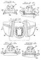
- a ceramic bracket 20 is illustrated in combination with a plastic wafer/pad 21 in mounting relation on a tooth 22.
- the bracket 21 is of the Begg or light-wire type having a vertically opening slot 25 formed in the body 26 of the bracket.
- a vertically extending pin slot 27 is formed in the body of the bracket and the bracket is provided with a base 28.
- the archwire slot 25 is adapted to receive an archwire, while a suitable pin will be used and received in the pin slot 27 to lock the archwire in place on the bracket.
- a tooth-engaging face 31 is provided to which is suitably adhesively secured the plastic pad 21.
- This embodiment particularly illustrates the addition of a plastic pad to the base of a bracket.
- the pad 21 includes a bracket-attaching side 33 and a tooth-attaching side 34.
- the bracket-attaching side of the plastic pad is shown in Fig. 4 and includes a plurality of detents of which detents 35 are of one shape and being somewhat oval, detents 36 are of another shape and being somewhat oval, and detents 37 being of another shape and generally circular.
- the detents 35, 36 and 37 are adapted to be received in indents formed in the tooth-facing surface of the bracket and the indents and detents serve to orient or align the plastic pad with the base of the bracket.
- the indents in the bracket-attaching face 31 of the bracket are shown in dotted lines in Figs. 2 and 3 but unnumbered for purposes of clarity. However, it will be appreciated that the indents will be formed and sized so as to define a mating relation with the detents on the pad. If desired, the detents/indents may be polygonal in shape or of any other shape.
- the plastic pad 21 has a slight arcuate form when viewed from above, as seen particularly in Fig. 5, but it may be appreciated that it could be flat and then bent to the shape of the tooth-attaching face of the bracket as needed when adhesively securing the pad to the bracket. Further, if the tooth-facing side of the bracket were flat, the plastic pad at least on the side to be attached to the bracket would also be flat.
- the plastic pad will be of a suitable plastic material for use in the mouth and which has some flexibility so that it can be buckled or distorted relative to the bracket and the tooth surface when debonding. It also must be compatible with the bonding adhesives used so that it can be properly bonded to the base of the ceramic bracket and also properly bonded to the enamel face of the tooth.
- the pad may be suitably molded or it may be stamped from a sheet of plastic material. Where the surfaces are specially formed, the surface area must be molded.
- One suitable plastic material is a polycarbonate material, although it can be appreciated that any other suitable material may be used. Further, the plastic material may be of a thermoplastic or thermosetting type.
- the shape of the wafer/pad may generally take the shape of the base of the bracket. With respect to the embodiment of Figs. 1 to 5, the pad is illustrated as being larger than the base in two directions, although it may be larger than the base in all directions. As particularly seen in Fig. 2, the plastic pad extends from the opposite sides of the bracket base. In another embodiment as described below, the plastic pad need not extend beyond the boundaries of the base.
- the plastic pad extends beyond the mesial and distal sides of the bracket base and is therefore engageable by pliers when the bracket is to be debonded.
- the sizing is such that a compressing force applied to the pad produces a buckling action or distortion in the pad without the beaks of the pliers applying any forces to the bracket that would cause fracture of the bracket during the debonding process. While it is not necessary that the pad extend beyond the occlusal and gingival edges of the bracket base, it can extend beyond these edges if so desired, as will be shown in the embodiment of Figs. 14 to 16.
- the thickness of the pad need only be such that it can be easily engaged by the beaks of the pliers during the debonding operation, and it is relatively thin, even though it may be thicker.
- debonding of the bracket 20 is accomplished by applying a compressive force to the mesial and distal edges of the pad that extend beyond the base of the bracket through plier beaks 44.
- the force is generally applied along the surface of the tooth.
- the beaks extend substantially perpendicular to the pad and following the engagement of the opposed edges of the pad and the application of a compressive or buckling force, a buckling or distortion of the pad along its width will be produced, as illustrated in exaggerated form in Fig. 10, which normally results in the breaking of the adhesive bond between the bracket-engaging side of the pad 33 and the bracket without necessitating the engagement or application of any force on the ceramic bracket by the beaks of the pliers.
- the size of the plastic wafer/pad designated by the numeral 21A is the same general size as the base of the bracket. While not shown to be any thicker than the pad 21, it could be of greater thickness if desired.
- This embodiment illustrates the use of a pliers of a different type having different beaks and the application of a compressive or buckling force to the pad from a different direction than the procedure shown in Fig. 10.
- the pliers includes knife-like beaks 48, with knife-like edges 48a that can engage the pad 21a, as seen in Fig. 12, from the opposite sides and still not engage the ceramic bracket 20. As further seen in Fig.
- the pad distorts or buckles and breaks the adhesive bond between the pad and the bracket and/or the pad and the tooth to facilitate debonding of the bracket without necessitating the application of any direct force to the bracket itself.
- the knife edges 48a could also engage the interface between the bracket 20 and the pad 21 or 21a to distort the pad away from the bracket to break the bond and release the bracket.
- the beaks may be of any suitable shape that would permit application of a compressive force generally along the surface of the tooth.
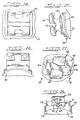
- this pad differs from the pad 21 only in that it has a greater curvature. It will be appreciated that any suitable curvature may be molded into the pad so that it will mate with the tooth-facing side of a bracket and the tooth.
- the pad 21C shown in Fig. 8 differs from pad 21 only in that it does not include any detents on the bracket-attaching side or any indents or roughened surfaces on the tooth-attaching side. It will be appreciated that the surfaces of the pad may be formed according to how it may best be utilized with respect to bonding to a bracket or bonding to a tooth. While the embodiment of Fig. 8 is shown to have a slight arcuate form, it may be in a flat form if so desired.
- the pad 21, as well as the other embodiments 21A, 21B and 21C, are shown to have a uniform thickness throughout, it will be appreciated that they may be formed with a varying thickness, depending upon the application desired.
- the pad 21D includes an upper curvate side 49a of one curvature and a lower or tooth-engaging side which is of a greater curvature and identified as 49b, giving it a varying thickness from side to side.
- the pad could be formed with a flat side on the side for attachment to the bracket where all brackets could be made with a flat tooth-facing surface, and with a curvature on the tooth-attaching side of the plastic pad that may be varied to mate with the curvature of a desired tooth.
- the plastic pad could be made with different curvatures on the tooth-engaging side.
- Figs. 14 to 16 The embodiment of Figs. 14 to 16 is shown to illustrate the use of the bonding pad of the invention with an edgewise bracket of the type disclosed in U.S. Patent 4,799,892, and which is generally designated by the numeral 50.
- This bracket includes a base 51 and extending therefrom a tie wing 52 having a horizontally opening archwire slot 53.
- a face 54 is provided at the tooth side of the base 51 and to which is adhesively bonded the plastic wafer/pad 56 which is sized to be greater on all four sides than the dimension of the base, as particularly seen in Fig. 15.
- the pad is shown attached to a tooth 57, and it will function in the same manner as the pads of previous embodiments in that when it is desired to debond the bracket from the tooth, a compressive/buckling force can be applied to the pad either from opposite mesial and distal sides or opposite occlusal and gingival sides in order to buckle or distort the pad and break the bond between the pad and bracket and/or also between the pad and the tooth without causing any pressure or forces to be directly applied to the bracket.
- Bracket 60 is also of ceramic and of the form that is described in U.S. Patent 4,852,514.
- Bracket 60 includes rotation control wings 61a and 61b and a tie wing 62 extending outwardly therefrom, and a horizontally opening archwire slot 63.
- a plastic base 65 is attached to the tooth-facing surface 66 of the bracket, and the base 65 includes a pair of ribs 67 which mate with recesses 68 on the bracket to provide an orientation or alignment between the bracket and the base.
- the bracket includes an auxiliary vertical groove 70 which aligns with a groove 71 in the pad to form a closed slot.
- the bracket-attaching side 72 of the pad is relatively flat other than having the ribs 67 and groove formation 71, while the tooth-engaging side 73 of the pad is arcuate to mate with the arcuate surface of tooth 74.
- Removal of the bracket 60 during a debonding process is similarly accomplished by providing a compressive/buckling force to the plastic base by use of pliers whereby the base is buckled to break the adhesive bond between the bracket and the pad and/or between the pad and the tooth.
- the brackets of Figs. 14 to 18 are only illustrative of edgewise-type brackets, and it can be appreciated the base of the invention may be used with any edgewise-type brackets as well as any light-wire bracket.
- the adhesive used to bond the pad/base to the tooth interferes with the direct application of compressive forces to the pad, the adhesive can be removed with a rotary dental bur to expose the edge(s) of the pad to readily accept the direct compressive forces.
- the present invention provides a pad or base and solves the problem of debonding of a ceramic bracket from a tooth without causing damage to the tooth enamel or fracture of the bracket, and permitting debonding of ceramic brackets to be quick and easy.
- plastic bonding pad of the invention is particularly useful to solve the debonding problem of ceramic brackets, it could also be used with metal or plastic brackets.
Landscapes
- Health & Medical Sciences (AREA)
- Oral & Maxillofacial Surgery (AREA)
- Dentistry (AREA)
- Epidemiology (AREA)
- Life Sciences & Earth Sciences (AREA)
- Animal Behavior & Ethology (AREA)
- General Health & Medical Sciences (AREA)
- Public Health (AREA)
- Veterinary Medicine (AREA)
- Dental Tools And Instruments Or Auxiliary Dental Instruments (AREA)
Claims (21)
- Kombination eines kieferorthopädischen keramischen Gestells (20) mit einer Basis (28) und einer an der Gestellbasis angebrachten Polsterschicht (21) für die Anbringung des Gestells an dem Zahn, dadurch gekennzeichnet, daß die genannte Polsterschicht (21) haftend an dem Gestell angebracht ist, aus einem flexiblen Werkstoff besteht und sich über wenigstens einen Rand des Gestells (20) hinaus erstreckt und zur Abnahme des Gestells von dem Zahn mit einem zangenartigen Instrument zur Ausübung einer zusammendrückenden Kraft in Eingriff gebracht werden kann, wobei sich die Polsterschicht wirft und leicht von dem Gestell und/oder dem Zahn getrennt werden kann.
- Kombination nach Anspruch 1, bei der die genannten Mittel in Form einer dünnen Kunststoffpolsterschicht mit einer glatten Fläche auf der dem Zahn anliegenden Seite ausgebildet sind.
- Kombination nach Anspruch 1, bei der die Kunststoffbindungspolsterschicht auf der dem Zahn anliegenden Seite Mittel aufweist, die die Bindung an den Zahn verstärken.
- Kombination nach Anspruch 3, bei der die genannten Mittel als dünne Kunststoffpolsterschicht mit einer aufgerauhten Fläche auf der dem Zahn anliegenden Seite ausgebildet sind.
- Kombination nach einem vorhergehenden Anspruch, bei der die dem Zahn zugewandte Seite des Gestells und die dem Gestell anliegende Seite der Polsterschicht Mittel zu Ausrichtung der Polsterschicht auf dem Gestell umfaßt, wenn die Polsterschicht auf dem Gestell durch Klebung angebracht wird.
- Kombination nach Anspruch 5, bei der die genannten Ausrichtmittel Vertiefungen auf der dem Zahn zugewandten Seite des Gestells oder der dem Gestell anliegenden Seite der Polsterschicht und Vorsprünge auf der jeweils anderen Seite der dem Zahn zugewandten oder der dem Gestell anliegenden Seite umfassen.
- Kombination nach Anspruch 5, bei der die genannten Ausrichtmittel Rippen auf der dem Zahn zugewandten Seite des Gestells oder der dem Gestell anliegenden Seite der Polsterschicht und die Rippen passend aufnehmende Aussparungen auf der anderen der dem Zahn zugewandten Seite oder der dem Gestell anliegenden Seite umfassen.
- Kombination nach einem vorhergehenden Anspruch, bei der die dem Gestell anliegende Seite der aus Kunststoff bestehenden Bindungspolsterschicht eben ist, um mit einer ebenen, dem Zahn zugewandten Gestellseite zusammenzupassen, und die dem Zahn anliegende Seite der Polsterschicht gekrümmt ist, um sich der gekrümmten Zahnoberfläche anzupassen.
- Kombination nach einem der Ansprüche 1 bis 7, bei der die dem Zahn anliegende Seite des Gestells gekrümmt ist, um mit einer gekrümmten Oberfläche eines Zahn zusammenzupassen, und die Kunststoffpolsterschicht gleichförmige Dicke hat und der dem Zahn zugewandten Seite des Gestells angepaßt werden kann.
- Kombination nach einem der Ansprüche 1 bis 5, bei der die dem Zahn zugewandte Seite des Gestells gekrümmt ist, um mit der gekrümmten Zahnoberfläche zusammenzupassen, und die Kunststoffpolsterschicht eine gleichmäßige Dicke und eine solche Flexibilität hat, daß sie normalerweise eben ist und zur Anformung an die gewölbte, dem Zahn zugewandte Seite des Gestells biegsam ist, wenn sie an dieser haftend angebracht wird.
- Kombination nach einem vorhergehenden Anspruch, bei der sich die Polsterschicht über die dem Zahn zugewandten Seite des Gestells in zwei oder mehr Richtungen hinaus erstreckt, damit sie beim Abnahmevorgang durch eine Zange leicht erfaßt werden kann.
- Kombination nach einem vorhergehenden Anspruch, bei der sich die Polsterschicht über die dem Zahn zugewandte Seite des Gestells in zwei oder mehr Richtungen hinaus erstreckt, so daß sie durch eine Zange erfaßt und bei der Abnahme verformt werden kann, um so den Bruch des Gestells zu vermeiden.
- Kombination nach einem vorhergehenden Anspruch, bei der die Polsterschicht eine Dicke hat,so daß sie bei dem Abnahmevorgang leicht durch eine Zange erfaßt werden kann.
- Kombination nach einem vorhergehenden Anspruch, bei der die Polsterschicht eine Dicke hat, so daß sie bei der Abnahme durch eine Zange ohne Berührung des Gestells leicht erfaßt und zusammengedrückt werden kann, damit das Gestell nicht bricht.
- Kombination nach einem vorhergehenden Anspruch, bei der die Kunststoffpolsterschicht aus Polycarbonatmaterial besteht.
- Kombination nach einem vorhergehenden Anspruch, bei der das Gestell einen sich vertikal öffnenden Bogendrahtschlitz hat.
- Kombination nach einem der Ansprüche 1 bis 15, bei der das Gestell einen sich horizontal öffnenden Bogendrahtschlitz hat.
- Kombination nach einem vorhergehenden Anspruch, bei der die Polsterschicht formgepreßt ist.
- Kombination nach einem der Ansprüche 1 bis 17, bei der die Polsterschicht aus einer Materialplatte gepreßt ist.
- Kombination nach einem vorhergehenden Anspruch, bei der die Polsterschicht aus einem Material besteht, das sich unter einer Kraft verformt oder verzieht, die kleiner als die zum Bruch des Keramikgestells erforderliche Kraft ist und die in der Lage ist, wenigstens die Haftbindung zwischen der Polsterschicht und dem Gestell und/oder der Polsterschicht und dem Zahn zu brechen.
- Zur Anbringung an einem Keramikgestell (20) geeignete Polsterschicht (21) mit einer mit dem Gestell in Eingriff kommenden Seite und einer für die Haftverbindung mit einem Zahn geeigneten, mit einem Zahn in Eingriff kommenden Seite in einer über die gegenüberliegenden Gestellseiten hinausreichenden Größe, dadurch gekennzeichnet, daß die genannte Polsterschicht aus einem Polycarbonat-artigen Kunststoff zur Haftbefestigung an dem Gestell geeignet ist und sich bei der Ausübung einer Quetschkraft mit einem zangenartigen Instrument auf die Polsterschicht wirft oder verformt, so daß die Bindung zwischen dem Gestell und der Polsterschicht und/oder der Polsterschicht und dem Zahn bricht, wobei während der Abnahme von der Zange keine Kraft auf das Gestell ausgeübt wird.
Applications Claiming Priority (2)
| Application Number | Priority Date | Filing Date | Title |
|---|---|---|---|
| US07/518,984 US5098288A (en) | 1990-05-04 | 1990-05-04 | Flexible bonding pad for an orthodontic bracket |
| US518984 | 1990-05-04 |
Publications (2)
| Publication Number | Publication Date |
|---|---|
| EP0455500A1 EP0455500A1 (de) | 1991-11-06 |
| EP0455500B1 true EP0455500B1 (de) | 1994-11-23 |
Family
ID=24066302
Family Applications (1)
| Application Number | Title | Priority Date | Filing Date |
|---|---|---|---|
| EP91304010A Expired - Lifetime EP0455500B1 (de) | 1990-05-04 | 1991-05-03 | Ziemlich nachgiebige Verbindungsschicht für orthodontische Brackets |
Country Status (4)
| Country | Link |
|---|---|
| US (1) | US5098288A (de) |
| EP (1) | EP0455500B1 (de) |
| JP (1) | JPH04227252A (de) |
| DE (1) | DE69105235T2 (de) |
Cited By (1)
| Publication number | Priority date | Publication date | Assignee | Title |
|---|---|---|---|---|
| US6914102B2 (en) | 2002-12-16 | 2005-07-05 | E. I. Du Pont De Nemours And Company | Thermoreactive hot-melt adhesives |
Families Citing this family (54)
| Publication number | Priority date | Publication date | Assignee | Title |
|---|---|---|---|---|
| US5474447A (en) * | 1990-04-03 | 1995-12-12 | Kunio Chikami | Device for correcting teeth irregularities |
| US5158452A (en) * | 1991-02-01 | 1992-10-27 | Rmo, Inc. | Orthodontic appliance mounting base |
| US5263859A (en) * | 1992-05-08 | 1993-11-23 | Tp Orthodontics, Inc. | Relatively flexible bonding pad for an orthodontic ceramic bracket |
| US5356288A (en) * | 1992-12-07 | 1994-10-18 | Howard Cohen | Dual orthodontic bracket |
| US5439379A (en) * | 1993-11-29 | 1995-08-08 | Minnesota Mining And Manufacturing Company | Ceramic orthodontic bracket with debonding channel |
| US5366372A (en) * | 1993-11-29 | 1994-11-22 | Minnesota Mining And Manufacturing Company | Method and apparatus for debonding ceramic orthodontic brackets |
| DE69522079T2 (de) * | 1994-11-29 | 2002-04-25 | Sankin Kogyo K.K., Otawara | Orthodontisches Bracket |
| US5711665A (en) * | 1995-12-19 | 1998-01-27 | Minnesota Mining & Manufacturing | Method and apparatus for bonding orthodontic brackets to teeth |
| US5746594A (en) * | 1996-03-05 | 1998-05-05 | Minnesota Mining & Manufacturing Co. | Orthodontic appliance with asymmetric bonding structure |
| US5782631A (en) * | 1996-12-11 | 1998-07-21 | Kesling; Christopher K. | Orthodontic appliance |
| US6482002B2 (en) | 2001-03-05 | 2002-11-19 | 3M Innovative Properties Company | Orthodontic appliance providing enhanced adhesive cure |
| US6902396B2 (en) | 2001-10-16 | 2005-06-07 | George Kyritsis | Orthodontic bracket and positioning system |
| US6592367B2 (en) * | 2001-10-16 | 2003-07-15 | George Kyritsis | Orthodontic bracket system |
| US6776614B2 (en) * | 2002-02-13 | 2004-08-17 | Lingualcare, Inc. | Modular system for customized orthodontic appliances |
| US6786720B1 (en) | 2002-04-10 | 2004-09-07 | Tp Orthodontics, Inc. | Epoxy resin bonding pad for a ceramic orthodontic appliance |
| US6685468B1 (en) | 2002-08-21 | 2004-02-03 | Tp Orthodontics, Inc. | Bondable orthodontic appliance with a polymer resin bonding base |
| US6746242B1 (en) | 2002-11-01 | 2004-06-08 | Tp Orthodontics, Inc. | Appliance with bilayer base |
| US7131836B1 (en) | 2002-11-01 | 2006-11-07 | Tp Orthodontics, Inc. | Bracket with bilayer base configured to produce a control value |
| US20040219470A1 (en) * | 2003-05-02 | 2004-11-04 | Ormco Corporation | Orthodontic bracket and method of debonding a bracket |
| US7549860B2 (en) * | 2004-12-13 | 2009-06-23 | 3M Innovative Properties Company | Hand instrument for detaching orthodontic brackets from teeth |
| US8308478B2 (en) * | 2005-03-01 | 2012-11-13 | Dentsply International Inc. | Methods for indirect bonding of orthodontic appliances |
| US7581949B2 (en) * | 2005-11-28 | 2009-09-01 | Ormco Corporation | Debonding pliers |
| US8026296B2 (en) | 2005-12-20 | 2011-09-27 | 3M Innovative Properties Company | Dental compositions including a thermally labile component, and the use thereof |
| US7776940B2 (en) * | 2005-12-20 | 2010-08-17 | 3M Innovative Properties Company | Methods for reducing bond strengths, dental compositions, and the use thereof |
| US7896650B2 (en) * | 2005-12-20 | 2011-03-01 | 3M Innovative Properties Company | Dental compositions including radiation-to-heat converters, and the use thereof |
| US20070142498A1 (en) * | 2005-12-20 | 2007-06-21 | Brennan Joan V | Dental compositions including thermally responsive additives, and the use thereof |
| CN1973793B (zh) * | 2006-09-30 | 2010-11-17 | 林久祥 | 牙齿矫正用传动矫治器 |
| US9539065B2 (en) | 2006-10-23 | 2017-01-10 | 3M Innovative Properties Company | Assemblies, methods, and kits including a compressible material |
| US20080096150A1 (en) * | 2006-10-23 | 2008-04-24 | 3M Innovative Properties Company | Dental articles, methods, and kits including a compressible material |
| EP2079246A4 (de) * | 2006-11-01 | 2012-08-22 | Fujitsu Ltd | Vorrichtung und verfahren zur drahtlosen kommunikation |
| US7670140B2 (en) * | 2006-12-20 | 2010-03-02 | 3M Innovative Properties Company | Orthodontic hand instrument for detaching brackets from teeth |
| NL2000871C2 (nl) * | 2007-09-21 | 2009-04-03 | Isidore Simon Markens | Orthodontische bracket. |
| RU2011109216A (ru) | 2008-08-13 | 2012-09-20 | Ормко Корпорейшн (Us) | Эстетический ортодонтический брекет и способ его изоготовления |
| AU2009238317B2 (en) * | 2008-11-14 | 2011-10-06 | Ormco Corporation | Surface treated polycrystalline ceramic orthodontic bracket and method of making same |
| WO2011017379A1 (en) * | 2009-08-05 | 2011-02-10 | Six Month Smiles Inc. | Orthodontic bracket system and method |
| US11382722B2 (en) | 2011-03-17 | 2022-07-12 | Cameron Mashouf | Orthodontic brackets for deciduous teeth |
| US10433933B2 (en) | 2011-03-17 | 2019-10-08 | Cameron Mashouf | Orthodontic bracket for use on deciduous teeth |
| USD660968S1 (en) | 2011-05-13 | 2012-05-29 | Rmo, Inc. | Orthodontic bracket |
| USD660435S1 (en) | 2011-05-13 | 2012-05-22 | Rmo, Inc. | Orthodontic bracket |
| USD660436S1 (en) | 2011-05-13 | 2012-05-22 | Rmo, Inc. | Orthodontic bracket |
| USD726318S1 (en) | 2013-01-17 | 2015-04-07 | Rmo, Inc. | Dental instrument for a self-ligating orthodontic clip |
| CA2955936C (en) | 2013-09-20 | 2017-09-12 | Brandon OWEN | Bracket system |
| US9844423B2 (en) * | 2013-10-03 | 2017-12-19 | Brandon Owen | Bracket extension system |
| US9861453B2 (en) * | 2013-10-03 | 2018-01-09 | Brandon Owen | Bracket extension system |
| USD721811S1 (en) | 2013-10-29 | 2015-01-27 | Rmo, Inc. | Orthodontic bracket |
| US9883924B2 (en) | 2014-06-12 | 2018-02-06 | Robert T. Rudman | Pocket orthodontic bonding pad |
| DE112016005848T5 (de) * | 2015-12-20 | 2018-08-30 | Grin Co., Ltd. | Kieferorthopädische Klammer |
| US10575928B2 (en) | 2017-09-21 | 2020-03-03 | Brandon Owen | Orthodontic bracket retention anchor |
| US11083548B2 (en) | 2018-01-26 | 2021-08-10 | Todd Evan Dickerson | Orthodontic anterior bite plate |
| US11331165B2 (en) | 2018-03-27 | 2022-05-17 | Klowen Braces, Inc. | Orthodontic treatment system |
| CN110801290B (zh) * | 2018-08-06 | 2025-10-31 | 中山大学附属口腔医院 | 壳状牙科器械及其制作方法 |
| WO2022081464A1 (en) * | 2020-10-14 | 2022-04-21 | Braces On Demand Inc. | Orthodontic devices and methods of use |
| US11903790B2 (en) | 2021-04-16 | 2024-02-20 | Braces On Demand, Inc. | Self-ligating orthodontic appliances |
| US11944515B2 (en) | 2021-04-16 | 2024-04-02 | Braces On Demand, Inc. | Orthodontic devices |
Family Cites Families (9)
| Publication number | Priority date | Publication date | Assignee | Title |
|---|---|---|---|---|
| US3250003A (en) * | 1960-12-08 | 1966-05-10 | Michael B Collito | Orthodontic method |
| US4186488A (en) * | 1977-11-11 | 1980-02-05 | Melvin Wallshein | Orthodontic bracket with multi-layer base |
| US4243386A (en) * | 1978-03-16 | 1981-01-06 | Gac International, Inc. | Orthodontic appliance |
| US4204325A (en) * | 1978-05-12 | 1980-05-27 | Arroyo Research and Consulting Company | Orthodontic bracket bonding system |
| EP0084443A3 (de) * | 1982-01-15 | 1984-03-28 | Peter J. Picard | Verfahren und Vorrichtungen für orthodontische Zwecke |
| CA1279215C (en) * | 1984-04-23 | 1991-01-22 | Johnson & Johnson Dental Products Company | Crystalline alumina orthodontic bracket |
| US4842512A (en) * | 1986-11-21 | 1989-06-27 | Tp Orthodontics, Inc. | Combination edgewise bracket |
| US4907965A (en) * | 1988-04-29 | 1990-03-13 | Johnson & Johnson Consumer Products, Inc. | Electrothermal dental debracketing tool and method of removal |
| US4902224A (en) * | 1988-12-19 | 1990-02-20 | Union Carbide Chemicals And Plastics Company Inc. | Crystalline orthodontic bracket |
-
1990
- 1990-05-04 US US07/518,984 patent/US5098288A/en not_active Expired - Lifetime
-
1991
- 1991-05-03 EP EP91304010A patent/EP0455500B1/de not_active Expired - Lifetime
- 1991-05-03 DE DE69105235T patent/DE69105235T2/de not_active Expired - Lifetime
- 1991-05-07 JP JP3101551A patent/JPH04227252A/ja active Pending
Cited By (1)
| Publication number | Priority date | Publication date | Assignee | Title |
|---|---|---|---|---|
| US6914102B2 (en) | 2002-12-16 | 2005-07-05 | E. I. Du Pont De Nemours And Company | Thermoreactive hot-melt adhesives |
Also Published As
| Publication number | Publication date |
|---|---|
| US5098288A (en) | 1992-03-24 |
| EP0455500A1 (de) | 1991-11-06 |
| DE69105235D1 (de) | 1995-01-05 |
| DE69105235T2 (de) | 1995-04-06 |
| JPH04227252A (ja) | 1992-08-17 |
Similar Documents
| Publication | Publication Date | Title |
|---|---|---|
| US5098288A (en) | Flexible bonding pad for an orthodontic bracket | |
| US5263859A (en) | Relatively flexible bonding pad for an orthodontic ceramic bracket | |
| US4904183A (en) | Orthodontic debonding method and tool | |
| US5176517A (en) | Dental undercut application device and method of use | |
| US5362232A (en) | Orthodontic appliance mounting base | |
| US10285783B2 (en) | Pocket orthodontic bonding pad | |
| US4209906A (en) | Orthodontic appliance (bracket and lock pin) | |
| US4850865A (en) | Orthodontic method and apparatus | |
| US5607301A (en) | Orthodontic bracket and method of mounting | |
| US7153130B2 (en) | Orthodontic appliance with removable insert | |
| US6464495B1 (en) | Gnathological bite opener | |
| US20190231488A1 (en) | Orthodontic anterior bite plate | |
| EP0128474B1 (de) | Orthodontische Vorrichtung | |
| JP2007512939A (ja) | アーチワイヤスロットライナを有するセラミック歯列矯正器具 | |
| JP2005521468A (ja) | 改良されたバッカルチューブ | |
| US4544353A (en) | Orthodontic appliance for direct bonding to a tooth | |
| EP1790309B1 (de) | Ablösungszange | |
| EP0389223A2 (de) | Stützklammer für eine zahnorthopädische Anordnung | |
| US6364659B1 (en) | Orthodontic bite opener | |
| US3686758A (en) | Orthodontic appliance | |
| JP5215381B2 (ja) | 改善された剥離特性を有するセラミック製歯科矯正ブラケット | |
| US10779910B2 (en) | Orthodontic bracket axis indicator | |
| US20190231487A1 (en) | Orthodontic anterior bite ramp | |
| WO2010123674A1 (en) | Ceramic orthodontic bracket including debonding channel | |
| US4600381A (en) | Orthodontic bracket remover |
Legal Events
| Date | Code | Title | Description |
|---|---|---|---|
| PUAI | Public reference made under article 153(3) epc to a published international application that has entered the european phase |
Free format text: ORIGINAL CODE: 0009012 |
|
| AK | Designated contracting states |
Kind code of ref document: A1 Designated state(s): BE DE FR GB IT NL |
|
| 17P | Request for examination filed |
Effective date: 19920410 |
|
| 17Q | First examination report despatched |
Effective date: 19930518 |
|
| GRAA | (expected) grant |
Free format text: ORIGINAL CODE: 0009210 |
|
| AK | Designated contracting states |
Kind code of ref document: B1 Designated state(s): BE DE FR GB IT NL |
|
| PG25 | Lapsed in a contracting state [announced via postgrant information from national office to epo] |
Ref country code: NL Effective date: 19941123 Ref country code: BE Effective date: 19941123 |
|
| REF | Corresponds to: |
Ref document number: 69105235 Country of ref document: DE Date of ref document: 19950105 |
|
| ET | Fr: translation filed | ||
| ITF | It: translation for a ep patent filed | ||
| NLV1 | Nl: lapsed or annulled due to failure to fulfill the requirements of art. 29p and 29m of the patents act | ||
| PLBE | No opposition filed within time limit |
Free format text: ORIGINAL CODE: 0009261 |
|
| STAA | Information on the status of an ep patent application or granted ep patent |
Free format text: STATUS: NO OPPOSITION FILED WITHIN TIME LIMIT |
|
| 26N | No opposition filed | ||
| REG | Reference to a national code |
Ref country code: GB Ref legal event code: IF02 |
|
| PGFP | Annual fee paid to national office [announced via postgrant information from national office to epo] |
Ref country code: GB Payment date: 20100305 Year of fee payment: 20 |
|
| PGFP | Annual fee paid to national office [announced via postgrant information from national office to epo] |
Ref country code: FR Payment date: 20100601 Year of fee payment: 20 |
|
| PGFP | Annual fee paid to national office [announced via postgrant information from national office to epo] |
Ref country code: DE Payment date: 20100527 Year of fee payment: 20 Ref country code: IT Payment date: 20100526 Year of fee payment: 20 |
|
| REG | Reference to a national code |
Ref country code: DE Ref legal event code: R071 Ref document number: 69105235 Country of ref document: DE |
|
| REG | Reference to a national code |
Ref country code: GB Ref legal event code: PE20 Expiry date: 20110502 |
|
| PG25 | Lapsed in a contracting state [announced via postgrant information from national office to epo] |
Ref country code: GB Free format text: LAPSE BECAUSE OF EXPIRATION OF PROTECTION Effective date: 20110502 |
|
| PG25 | Lapsed in a contracting state [announced via postgrant information from national office to epo] |
Ref country code: DE Free format text: LAPSE BECAUSE OF EXPIRATION OF PROTECTION Effective date: 20110503 |