EP0455820B1 - Verfahren zum verbessern eines fehlerhaften spritzgiessvorganges bei einer spritzgiessmaschine - Google Patents
Verfahren zum verbessern eines fehlerhaften spritzgiessvorganges bei einer spritzgiessmaschine Download PDFInfo
- Publication number
- EP0455820B1 EP0455820B1 EP90917098A EP90917098A EP0455820B1 EP 0455820 B1 EP0455820 B1 EP 0455820B1 EP 90917098 A EP90917098 A EP 90917098A EP 90917098 A EP90917098 A EP 90917098A EP 0455820 B1 EP0455820 B1 EP 0455820B1
- Authority
- EP
- European Patent Office
- Prior art keywords
- molding
- parameters
- values
- faulty
- time
- Prior art date
- Legal status (The legal status is an assumption and is not a legal conclusion. Google has not performed a legal analysis and makes no representation as to the accuracy of the status listed.)
- Expired - Lifetime
Links
- 238000000465 moulding Methods 0.000 title claims abstract description 171
- 238000000034 method Methods 0.000 title claims abstract description 69
- 238000001746 injection moulding Methods 0.000 title claims abstract description 34
- 230000002950 deficient Effects 0.000 title abstract description 9
- 238000011156 evaluation Methods 0.000 claims abstract description 46
- 238000002347 injection Methods 0.000 claims abstract description 27
- 239000007924 injection Substances 0.000 claims abstract description 27
- 238000004519 manufacturing process Methods 0.000 claims abstract description 17
- 230000008569 process Effects 0.000 claims description 49
- 230000000694 effects Effects 0.000 claims description 3
- 239000011347 resin Substances 0.000 abstract description 13
- 229920005989 resin Polymers 0.000 abstract description 13
- 238000001514 detection method Methods 0.000 abstract 1
- 238000005259 measurement Methods 0.000 description 3
- 238000005070 sampling Methods 0.000 description 3
- 230000004075 alteration Effects 0.000 description 2
- 238000013500 data storage Methods 0.000 description 2
- 238000003745 diagnosis Methods 0.000 description 2
- 238000010438 heat treatment Methods 0.000 description 2
- 230000004044 response Effects 0.000 description 2
- 230000002123 temporal effect Effects 0.000 description 2
- 230000008859 change Effects 0.000 description 1
- 238000010276 construction Methods 0.000 description 1
- 238000011161 development Methods 0.000 description 1
- 238000010586 diagram Methods 0.000 description 1
- 230000002452 interceptive effect Effects 0.000 description 1
- 230000007246 mechanism Effects 0.000 description 1
- 238000012986 modification Methods 0.000 description 1
- 230000004048 modification Effects 0.000 description 1
- 239000012778 molding material Substances 0.000 description 1
- 230000003252 repetitive effect Effects 0.000 description 1
Images


Classifications
-
- B—PERFORMING OPERATIONS; TRANSPORTING
- B29—WORKING OF PLASTICS; WORKING OF SUBSTANCES IN A PLASTIC STATE IN GENERAL
- B29C—SHAPING OR JOINING OF PLASTICS; SHAPING OF MATERIAL IN A PLASTIC STATE, NOT OTHERWISE PROVIDED FOR; AFTER-TREATMENT OF THE SHAPED PRODUCTS, e.g. REPAIRING
- B29C45/00—Injection moulding, i.e. forcing the required volume of moulding material through a nozzle into a closed mould; Apparatus therefor
- B29C45/17—Component parts, details or accessories; Auxiliary operations
- B29C45/76—Measuring, controlling or regulating
- B29C45/766—Measuring, controlling or regulating the setting or resetting of moulding conditions, e.g. before starting a cycle
Definitions
- the present invention relates to a method for taking countermeasures against faulty molding in an injection molding machine, and more particularly, to a method which makes restoration to a nondefective molding condition, with the aid of an expert system, when faulty molding takes place during the mass production of molded products.
- a molding condition for carrying out an injection molding cycle includes a large number of molding parameters such as injection pressure, injection time, etc.
- optimum values of various molding parameters must be determined.
- the optimum molding condition also varies in dependence on the type of products. For these reasons, the optimum molding condition is generally determined in a trial-and-error manner by repeating an operation of carrying out an injection molding cycle in accordance with a tentative molding condition, and then changing the molding condition in accordance with the type of faulty molding found in the resultant molded product. Therefore, proper and quick setting of an optimum molding condition requires a skilled person having wide knowledge and experience.
- an expert system which enables an unskilled person to set the optimum molding condition, has been recently developed.
- the expert system which comprises programs and a database prepared beforehand on the basis of the knowledge and experience of skilled persons, is arranged to effect an optimum molding condition setting process on an interactive basis with an operator.
- an injection molding machine repeats the injection molding cycle in accordance with the optimum molding condition thus established, to perform the mass production of molded products.
- the injection molding cycle is implemented repeatedly under the same optimum molding condition, without changing the molding condition. Nevertheless, defective moldings are produced occasionally.
- a diagnosis is conducted to identify the cause of the faulty molding, and the optimum molding condition is set again in accordance with results of the diagnosis.
- the mechanism of occurrence of faulty molding is complicated, and various molding parameters are involved therein. Also, there are various types of faulty molding such as burrs, sinks, etc.
- similar faulty molding is not necessarily caused by similar improper molding parameters. This means that, when faulty molding takes place, the knowledge and experiences of the skilled are required to determine which ones of the many molding parameters should be changed and how much they should be changed to make restoration to a normal molding condition.
- the expert system may be considered to use the expert system to make a restoration process when faulty molding occurs during the mass production of molded products just as it is used to establish an optimum molding condition prior to the start of the mass production.
- the conventional expert system is primarily designed from a viewpoint of enabling determination of a new optimum molding condition on the basis of various molding parameter values detected as the injection molding cycle is repeatedly tried, with molding parameter values changed, and data indicative of the conformity of molded products and entered by an operator during the repetitive molding. According to the conventional expert system, therefore, it is impossible to efficiently perform a restoration process which is required upon occurrence of faulty molding during the mass production of molded products conducted under the same optimum molding condition.
- the object of the present invention is to provide a method for taking countermeasures against faulty molding in an injection molding machine, which is capable of properly and quickly making restoration to a nondefective molding condition, with the aid of an expert system, when faulty molding occurs during the mass production of molded products.
- a method for taking countermeasures against faulty molding in an injection molding machine comprising the steps of:
- the reference values of the molding parameters are measured in advance during molding where non-defective products are molded.
- at least one threshold value may be set beforehand, which is associated with a deviation between each molding parameter value detected at the time of faulty molding and the reference value of each molding parameter, and the deviation of each molding parameter may be compared with the associated threshold value, to make the evaluation on that parameter.
- the molding parameters, the threshold values each associated with a corresponding one of the molding parameters, and the countermeasure processes against faulty molding each associated with a corresponding one of combinations of evaluations on the molding parameters may be selected or set beforehand on the basis of the knowledge and experience of skilled persons.
- the evaluation on each molding parameter is effected by comparing each molding parameter value, detected when faulty molding occurs during the mass production of molded products, with the preset reference value of each molding parameter, and that one of the preset countermeasure processes against faulty molding which corresponds to a combination of the evaluations on the plurality of molding parameters is selectively carried out.
- the molding parameters are selected beforehand based on the knowledge and experience of the skilled persons.
- the deviation between each molding parameter value detected upon occurrence of faulty molding and the reference value of each molding parameter preset during the nondefective molding is detected, and the evaluation on each molding parameter may be effected by comparing the deviation with the threshold value preset based on the knowledge and experiences of the skilled persons.
- a corresponding one of countermeasure processes against faulty molding which are preset based on the knowledge and experiences of the skilled persons is selectively carried out.
- restoration upon occurrence of faulty molding can be carried out in a manner as if such restoration were made by a skilled person, without intervention of the skilled person.
- An injection molding machine embodying a preferred method according to the present invention comprises various units such as an injection unit, a mold-clamping unit, etc.
- the injection unit which is provided with a screw 1 disposed in a heating cylinder, not shown, an injection servomotor 2 for driving the screw in the axial direction, and a servomotor (not shown) for rotating the screw 1, is so designed as to move the screw 1 axially, to thereby inject molding material (resin) plasticized and kneaded within the heating cylinder into a mold, not shown.
- the injection servomotor 2 is mounted with a pulse coder 3 for detecting the rotary position of the motor (axial movement position of the screw), and the screw 1 is mounted with a pressure sensor 4 for detecting a resin pressure (axial reaction force applied by the molten resin to the screw).
- the injection molding machine is provided with a numerical control apparatus (hereinafter referred to as an NC apparatus) 100 which cooperates with a programmable machine controller (mentioned later) to control the various units of the injection molding machine.
- the NC apparatus 100 comprises a numerical control microprocessor (hereinafter referred to as NCCPU) 112 for controlling the various servomotors through a servo interface 111 and various servo circuits (only the servo circuit for the injection servomotor 2 is indicated by reference numeral 103), and the respective servo circuits are connected with pulse coders (only the pulse coder for the injection servomotor 2 is denoted by reference numeral 3).
- a random-access memory (RAM) 104 for temporal data storage, etc., and a read-only memory (ROM) 115 storing therein a management program for controlling the whole injection molding machine are connected to the NCCPU 112.
- RAM random-access memory
- ROM read-only memory
- the NC apparatus 100 is further provided with a microprocessor (hereinafter referred to as PMCCPU) 114 for the programmable machine controller, to which connected are a ROM 117 storing therein a sequence program for controlling the sequential operation of the injection molding machine, and a RAM 110 for temporal data storage, etc.
- the RAM 110 is designed to store the later-mentioned two tables T1 and T2 for the countermeasure process against faulty molding, mentioned later.
- a bus arbiter controller 113 (hereinafter referred to as BAC) interposed between the CPUs 112 and 114 is connected with respective busses of a shared memory 105, an input circuit 106, and an output circuit 107, so that either one of the CPUs is selectively rendered to be accessible, under the control of the BAC 113, to a desired one of the elements 105 to 107 in each arithmetic operation cycle of the CPUs 112 and 114.
- the shared memory 105 which consists of a nonvolatile RAM has a program storage section for storing, e.g., NC programs for controlling the injection molding machine, and a setting section for storing various setting values, parameters and macro variables indicative of a molding condition.
- the input circuit 106 is connected to, e.g., various sensors provided in the various units of the injection molding machine, while the output circuit 107 is connected to various servo circuits, including the servo circuit 103, and an address generator 118 which is in turn connected to two RAMs 108 and 109 accessible from the PMCCPU 114.
- the RAM 108 which is connected to an A/D converter 101 connected to the pressure sensor 4, is designed to store an A/D converter output, indicative of a resin pressure, in an address area specified by an output signal supplied from the address generator 118.
- the RAM 109 connected to a counter 102 for adding up feedback pulses received from the pulse coder 3, is designed to store a counter output, indicative of a screw position, in an address area specified by an output from the address generator.
- CRT/MDI CRT display unit
- the PMCCPU 114 is designed to compare the deviation between each molding parameter and its reference value with a corresponding threshold value, to thereby make an evaluation on each parameter, and perform a required countermeasure process in accordance with a combination of evaluation results on the individual parameters when faulty molding takes place during the mass production of molded products.
- the types of molding parameters for evaluation, the threshold value of each parameter, and contents of the countermeasure processes are set appropriately on the basis of knowledge and experiences of skilled persons.
- Each parameter is subjected to 5-level evaluation of "2,” “1,” “0,” “-1,” and “-2” in accordance with the result of comparison between the deviation ⁇ xi of each parameter value, obtained upon occurrence of faulty molding, from its reference value (xis) and the first to the fourth threshold value values Ki1 to Ki4.
- the evaluation on each parameter will be effected in the following way; if the parameter value given when faulty molding takes place deviates from its reference value considerably in the positive direction ( ⁇ xi ⁇ Ki1), then the evaluation result will be "2," and if it deviates slightly in the positive direction (Ki1 > ⁇ xi ⁇ Ki2), then the evaluation result will be "1.” If there is no substantial deviation (Ki2 > ⁇ xi > - Ki3), then the evaluation result will be "0.” On the other hand, if the parameter value slightly deviates from the reference value in the negative direction, then the evaluation result will be "-1,” and if it deviates significantly in the negative direction ( ⁇ xi ⁇ -Ki4), then the evaluation result will be "-2.”
- the input data is stored in the RAM 110 as the table T1 shown in Table 1 below.
- the reference value xis of each parameter is not yet entered.
- the input data is stored in the RAM 110, under the control of the PMCCPU 114, as the table T2 shown in Table 2 below.
- countermeasure processes against faulty molding each of which is represented by a corresponding one of combinations of evaluation results on the five parameters, are set in the table T2.
- Table 2 shows only first to third countermeasure processes which respectively correspond to first to third evaluation combinations of "2, 0, 0, 0, 0,” "2, 2, 0, 0, 0,” and "2, 1, 0, 0, 0.” Those combinations of evaluation results which are associated with faulty molding that cannot take place during the mass production of molded products, and countermeasure processes corresponding thereto are not set.
- an optimum molding condition for effecting an injection molding cycle for mass production are determined in a conventional manner, and stored in the setting section of the shared RAM 105. Thereafter, in accordance with the sequence program stored in the ROM 117 and the NC program stored in the shared RAM 105, sequence control is performed by the PMCCPU 114, and servomotors for individual axes are drivingly controlled by the NCCPU 112, so that one injection molding cycle is carried out.
- an analog output from the pressure sensor 4 indicative of a resin pressure applied to the screw 1 is converted into a digital signal by the A/D converter 101, and feedback pulses delivered from the pulse coder 3 with movement of the screw 1 are added up by the counter 102.
- the thus accumulated value represents a screw position.
- the PMCCPU 114 reads an injection start command from the program while executing the injection molding cycle, it causes the address generator 118 to operate. Namely, upon start of an injection process, the address generator 118 begins delivery of an addressing output (sampling command) to the RAMs 108 and 109. This addressing output is updated for each sampling cycle until a hold process is completed. As a result, the injection/hold pressure and the screw position in each sampling cycle are stored in corresponding address regions of the RAMs 108 and 109.
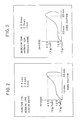
- the PMCCPU 114 measures, by means of timers, an injection time from the start of the injection process to the moment the screw 1 reaches a hold starting position, a metering time from the start of a metering process to the moment the screw 1 reaches a metering point, etc., determines a cushion amount in accordance with a screw position at the time the hold process is completed, and stores the injection time, the metering time and the cushion amount in, e.g., the shared RAM 105. Under the control of the PMCCPU 114, the injection time, the metering time and the cushion amount are displayed by the CRT display controller on its CRT screen, as shown in Fig. 2.
- a screw position vs. injection/hold pressure curve is graphically displayed on the CRT screen, as shown in Fig. 2, on the basis of the sampled data transferred from the RAMs 108 and 109 to the pressure data RAM and the screw position data RAM of the CRT display controller.
- the operator With reference to the screw position vs. injection/hold pressure curve and in consideration of the type of the mold used, the type of resin, the molding condition, etc., the operator sets the screw position (e.g. 10mm) at the time the resin passes the gate, and the screw position (e.g. 30mm) at the time of resin filling. In response to this, these two screw positions are stored in the shared RAM 105 under the control of the PMCCPU 114.
- the PMCCPU 114 When the operator enters a continuous molding command through the CRT/MDI 119 after setting the screw positions at the time of passing the gate and at the time of filling, the PMCCPU 114 reads, from the shared RAM 105, the injection time, the metering time and the cushion amount in the above-mentioned one injection molding cycle, and then writes the thus read data, as reference values, in corresponding storage areas of the table T1.
- the CPU 114 specifies those address regions of the RAM 109 in which the set screw positions at the time of gate passage and at the time of filling are stored, reads the sampled injection pressures at the time of gate passage and at the time of filling from the same address regions of the RAM 108, and writes, as the reference values, the thus read data into the storage areas of the table T1 respectively associated with pressures at the time of gate passage and filling.
- the injection molding cycle is repeated in the same manner as in the above-mentioned one injection molding cycle, so as to carry out the mass production of molded products.
- the molding condition is not changed during the mass production. Nevertheless, defective products are occasionally produced.
- Fig. 3 shows a display example of the injection time, the metering time, the cushion amount and the screw position vs. injection/hold pressure curve in an injection molding cycle which has developed faulty molding.
- the PMCCPU 114 reads, from the timers, the injection time x1 and the metering time x2 in the injection molding cycle where the faulty molding occurs, determines the cushion amount x3 based on the screw position at the time the hold process is completed, and reads, from the RAM 108, the pressure x4 at the time of gate passage and the pressure x5 at the time of filling (step S1). Then, the CPU 114 reads the reference values x1s to x5s of the parameters from the table T1, and calculates the deviations ⁇ x1 to ⁇ x5 between the measured values x1 to x5 of the parameters and their corresponding reference values x1s to x5s (step S2).
- the evaluation result will be "2" if ⁇ xi ⁇ Ki1, or "1” if Ki1 > ⁇ xi ⁇ Ki2, or "0” if Ki2 > ⁇ xi > -Ki3, or "-1” if -Ki3 ⁇ ⁇ x1 > -Ki4, or "-2” if ⁇ Xi ⁇ -Ki4.
- the PMCCPU 114 determines a pattern indicative of the combination of the evaluations on the five molding parameters.
- the remaining second, third and fifth parameter values are nearly equal to or show small deviations from the reference values
- the evaluation results on the first to fifth parameters are respectively denoted as "-1,” "0,” “0,” “-2,” and "0,” for instance.
- the combination of evaluations in this case is represented by a pattern "-1, 0, 0, -2, 0."
- the PMCCPU 114 retrieves, from the table T2, a pattern that matches the pattern indicative of the combination of the evaluations and determined as described above, and reads from the table T2 that information on the countermeasure process which corresponds- to the retrieved pattern, e.g., the information "Lower the nozzle temperature by 2 degrees” which corresponds to the pattern "-1, 0, 0, -2, 0" (step S4). And the CPU 114 changes the optimum molding condition in accordance with the countermeasure process information (step S5).
- the CPU 114 sets a value, as the optimum nozzle temperature in the shared RAM 105, which is 2 degrees lower than the optimum nozzle temperature that has been set in the shared RAM 105 as one of the parameter values making up the optimum molding condition, in place of the previous optimum nozzle temperature.
- the injection molding machine When the molding condition is changed so that the countermeasure process against faulty molding shown in Fig. 4 is completed in this manner, the injection molding machine repeatedly carries out the injection molding cycle in accordance with the updated molding condition, thereby performing the mass production of molded products. If similar or different faulty molding still takes place after the molding condition is changed (if necessary, e.g., after elapse of a time period required for the nozzle temperature to rise), the operator enters the countermeasure command against faulty molding again, to cause the PMCCPU 114 to restart the countermeasure process against faulty molding.
- the information, indicative of the countermeasure process which must be taken upon occurrence of faulty molding is stored in the table T2.
- a cause of such faulty molding may be also stored.
- the countermeasure process information and the cause of the faulty molding are displayed on the CRT screen.
- the molding condition is automatically changed in accordance with the countermeasure process information retrieved from the table T2.
- the countermeasure process information may be displayed on the CRT screen, so as to urge the operator to change the molding condition.
- the NC apparatus waits until the operator completes the alteration of the molding condition.
- the countermeasure process information may be displayed on the CRT screen even when the molding condition is automatically changed. This will furnish the operator with a rough idea about when the alteration of the molding condition will be completed. This is especially convenient to a case where a certain time is required until an updated molding condition is actually attained, e.g., in a case where the nozzle temperature is changed.
Landscapes
- Engineering & Computer Science (AREA)
- Manufacturing & Machinery (AREA)
- Mechanical Engineering (AREA)
- Injection Moulding Of Plastics Or The Like (AREA)
- Testing Or Calibration Of Command Recording Devices (AREA)
Claims (9)
- Verfahren zum Ergreifen von Gegenmaßnahmen bei fehlerhaftem Spritzgießen in einer Spritzgießmaschine, umfassend die Schritte:a) Ermitteln der Werte einer Vielzahl von Spritzgießparametern während der Massenproduktion von Spritzgießerzeugnissen,b) Ermitteln des Auftretens eines fehlerhaften Spritzgießens,c) Anwenden eines Expertensystems zur Auswahl eines in Frage kommenden Gegenmaßnahmevorgangs aus einer Vielzahl von festgelegten Gegenmaßnahmevorgängen zur Korrektur des fehlerhaften Spritzgießens, wobei bei dem Auswahlvorgang Gebrauch gemacht wird von den ermittelten Werten aus der Vielzahl von Spritzgießparametern und außerdem von festgesetzten Referenzwerten dafür, undd) Inkraftsetzen des ausgewählten Gegenmaßnahmevorgangs, dadurch gekennzeichnet,
daß der Auswahlvorgang folgende Schritte umfaßt:
Vergleichen jedes der ermittelten Werte der Spritzgießparameter, die beim Auftreten eines fehlerhaften Spritzgießens vorhanden sind, mit den entsprechenden dafür vorgegebenen Referenzwerten,
Vornehmen einer Bewertung des jeweils ermittelten Wertes in Abhängigkeit davon, ob er von seinem entsprechenden vorgegebenen Referenzwert abweicht oder nicht, und in dem Fall, daß er abweicht, in Abhängigkeit von dem Differenzwert,
Kombinieren der Bewertungen der ermittelten Werte zu einer Bewertungskombination
und Auswahl des in Frage kommenden Gegenmaßnahmevorgangs durch Vergleichen der genannten Bewertungskombination mit einer Tabelle, die eine Vielzahl von bestimmten Bewertungskombinationen zusammen mit bestimmten Gegenmaßnahmevorgängen entsprechend den betreffenden Kombinationen der bestimmten Bewertungskombinationen speichert. - Verfahren nach Anspruch 1, wobei die vorgegebenen Referenzwerte der Spritzgießparameter im voraus während des Spritzgießens gemessen werden, währenddessen fehlerfreie Produkte im Spritzgießvorgang erstellt werden.
- Verfahren nach Anspruch 1 oder 2, umfassend ferner einen Schritt zur vorherigen Einstellung zumindest eines Schwellwertes, der einer Abweichung zwischen jedem der Spritzgießparameterwerte, die zum Zeitpunkt fehlerhaften Spritzgießens ermittelt sind, und dem vorgegebenen Referenzwert des jeweiligen Spritzgießparameterwertes zugehörig ist,
und wobei die betreffende Abweichung des jeweiligen Spritzgießparameterwertes von dessen vorgegebenen Referenzwert mit dem genannten zugehörigen zumindest einen Schwellwert verglichen und dadurch die betreffende Bewertung des jeweils ermittelten Spritzgießparameterwertes vorgenommen wird. - Verfahren nach Anspruch 3, wobei für jede Abweichung zwischen einem Spritzgießparameterwert und dessen vorgegebenen Referenzwert zuvor eine Vielzahl von Schwellwertwerten entsprechend unschiedlichen Werten der betreffenden Abweichung festgesetzt wird.
- Verfahren nach Anspruch 4, wobei die Bewertungskombination für den jeweiligen Spritzgießparameterwert eine Kombination von Anzeigen darüber ist, welche Schwellwertwerte durch die Abweichung zwischen dem Spritzgießparameterwert und dessen vorgegebenen Referenzwert überschritten sind.
- Verfahren nach Anspruch 3, 4 oder 5, wobei die Vielzahl der Spritzgießparameter, der zumindest eine dem jeweiligen Spritzgießparameter zugehörige Schwellwert und die Gegenmaßnahmevorgänge bei fehlerhaftem Spritzgießen, die jeweils einer entsprechenden Kombination der Bewertungskombinationen bezüglich der Vielzahl von Spritzgießparametern zugehörig sind, zuvor auf der Grundlage von Wissen und Erfahrung von erfahrenen Personen festgelegt werden.
- Verfahren nach irgendeinem vorhergehenden Anspruch, wobei ein Spritzgießzustand in Übereinstimmung mit demjenigen Gegenmaßnahmevorgang bei fehlerhaftem Spritzgießen geändert wird, der einer Kombination der Bewertungen bezüglich der Vielzahl von Spritzgießparametern entspricht.
- Verfahren nach irgendeinem vorhergehenden Anspruch, wobei eine Information angezeigt wird, die denjenigen Gegenmaßnahmevorgang bei fehlerhaftem Spritzgießen wiedergibt, welcher einer Kombination der Bewertungen hinsichtlich der Vielzahl von Spritzgießparametern entspricht.
- Verfahren nach irgendeinem vorhergehenden Anspruch, wobei die Vielzahl der Spritzgießparameter eine Einspritzzeit, eine Bemessungszeit, eine Puffergröße, einen Druck zum Zeitpunkt des Passierens eines Durchlasses und einen Druck zum Füllzeitpunkt umfaßt.
Applications Claiming Priority (3)
| Application Number | Priority Date | Filing Date | Title |
|---|---|---|---|
| JP303253/89 | 1989-11-24 | ||
| JP1303253A JP2586954B2 (ja) | 1989-11-24 | 1989-11-24 | 射出成形機における成形不良対策方法 |
| PCT/JP1990/001519 WO1991008097A1 (fr) | 1989-11-24 | 1990-11-21 | Procede de correction de defauts de moulage dans une machine de moulage par injection |
Publications (3)
| Publication Number | Publication Date |
|---|---|
| EP0455820A1 EP0455820A1 (de) | 1991-11-13 |
| EP0455820A4 EP0455820A4 (en) | 1991-12-11 |
| EP0455820B1 true EP0455820B1 (de) | 1994-07-13 |
Family
ID=17918726
Family Applications (1)
| Application Number | Title | Priority Date | Filing Date |
|---|---|---|---|
| EP90917098A Expired - Lifetime EP0455820B1 (de) | 1989-11-24 | 1990-11-21 | Verfahren zum verbessern eines fehlerhaften spritzgiessvorganges bei einer spritzgiessmaschine |
Country Status (5)
| Country | Link |
|---|---|
| US (1) | US5225122A (de) |
| EP (1) | EP0455820B1 (de) |
| JP (1) | JP2586954B2 (de) |
| DE (1) | DE69010671T2 (de) |
| WO (1) | WO1991008097A1 (de) |
Cited By (5)
| Publication number | Priority date | Publication date | Assignee | Title |
|---|---|---|---|---|
| EP0566738A4 (de) * | 1990-11-30 | 1993-08-27 | Fanuc Ltd | Verfahren zum bestimmen der spritzgiessbedingungen. |
| DE4434654A1 (de) * | 1994-09-28 | 1996-04-04 | Arburg Gmbh & Co | Verfahren zur Beeinflussung zyklisch ablaufender Prozesse |
| DE4434653A1 (de) * | 1994-09-28 | 1996-04-04 | Arburg Gmbh & Co | Verfahren zur Beeinflussung von Maschineneinstellgrößen sowie Vorrichtung zur Durchführung des Verfahrens |
| GB2316193A (en) * | 1996-08-12 | 1998-02-18 | Siebolt Hettinga | Optimising injection moulding |
| US6696649B2 (en) | 2000-08-02 | 2004-02-24 | Sumitomo Wiring Systems, Ltd. | Weight inspecting apparatus |
Families Citing this family (15)
| Publication number | Priority date | Publication date | Assignee | Title |
|---|---|---|---|---|
| EP0446364B1 (de) * | 1989-09-18 | 1996-04-24 | Fujitsu Limited | Laserabtaster für strichkodeleser |
| DE4219259A1 (de) * | 1992-06-12 | 1993-12-16 | Karl Hehl | Verfahren zur Steuerung einer Kunststoff-Spritzgießmaschine |
| DE4334134B4 (de) * | 1993-10-07 | 2005-09-29 | Battenfeld Kunststoffmaschinen Ges.M.B.H. | Verwendung einer Leistungs- und Ansteuerelektronik an einer Spritzgießmaschine |
| US5518671A (en) * | 1993-10-20 | 1996-05-21 | Nissei Plastic Industrial Co., Ltd. | Method of setting molding conditions for an injection molding machine |
| CA2142754C (en) * | 1994-05-20 | 1999-04-13 | Thomas H. Richards | Clamp control for injection molding machine |
| US5456870A (en) * | 1994-05-20 | 1995-10-10 | Van Dorn Demag Corporation | Barrel temperature state controller for injection molding machine |
| AT404076B (de) * | 1994-08-31 | 1998-08-25 | Battenfeld Kunststoffmasch | Verfahren zum automatischen bestimmen des optimalen arbeitspunktes einer spritzgiessmaschine |
| JP2805189B2 (ja) * | 1994-11-10 | 1998-09-30 | 日精樹脂工業株式会社 | 射出成形機 |
| JP4236709B2 (ja) * | 1996-02-15 | 2009-03-11 | ファナック株式会社 | 射出成形機における成形データ収集方法および成形条件取得方法 |
| US5914884A (en) * | 1997-01-02 | 1999-06-22 | General Electric Company | Method for evaluating moldability characteristics of a plastic resin in an injection molding process |
| EP1166988B1 (de) * | 2000-06-21 | 2003-10-29 | Orac NV | Verfahren und Vorrichtung zum Anbringen von Reliefverzierungen auf langgestreckten Gegenständen |
| US6914537B2 (en) * | 2001-05-25 | 2005-07-05 | Toshiba Machine Co., Ltd. | Method for monitoring operation data of an injection-molding machine |
| US7534378B2 (en) * | 2004-03-03 | 2009-05-19 | Rexam Prescription Products Inc. | Plastic forming process monitoring and control |
| JP7362530B2 (ja) * | 2020-03-31 | 2023-10-17 | 住友重機械工業株式会社 | 射出成形機、射出成形システム |
| CN118244728A (zh) * | 2024-05-27 | 2024-06-25 | 徐州鸿丰高分子材料有限公司 | 一种环氧树脂生产制备智能监控控制系统 |
Family Cites Families (12)
| Publication number | Priority date | Publication date | Assignee | Title |
|---|---|---|---|---|
| US4421467A (en) * | 1982-03-11 | 1983-12-20 | Hpm Corporation | Injection molding machine diagnostic system |
| JPS62249722A (ja) * | 1986-04-24 | 1987-10-30 | Japan Steel Works Ltd:The | 射出成形機の適応制御方法 |
| DE3639292A1 (de) * | 1986-11-17 | 1988-05-26 | Battenfeld Gmbh | Verfahren zum spritzgiessen von thermoplastischen kunststoffen |
| JPS63209917A (ja) * | 1987-02-27 | 1988-08-31 | Toshiba Corp | 射出成形支援エキスパ−トシステム |
| JPS6424719A (en) * | 1987-07-20 | 1989-01-26 | Komatsu Mfg Co Ltd | Controlling apparatus for injection molding machine |
| DE3827285A1 (de) * | 1987-08-13 | 1989-02-23 | Toshiba Machine Co Ltd | Steuervorrichtung fuer eine spritzgiessmaschine |
| US4816197A (en) * | 1988-04-12 | 1989-03-28 | Hpm Corporation | Adaptive process control for injection molding |
| JPH0720651B2 (ja) * | 1988-11-09 | 1995-03-08 | 東芝機械株式会社 | 射出成形機の最適成形条件設定システム |
| JP2927434B2 (ja) * | 1988-11-25 | 1999-07-28 | ファナック株式会社 | 射出成形機のオンラインai管理システム |
| JP2902657B2 (ja) * | 1988-12-21 | 1999-06-07 | 東芝機械株式会社 | 射出成形機における成形条件の最適化制御システム |
| US5056999A (en) * | 1989-04-25 | 1991-10-15 | Howmet Corporation | Apparatus for forming objects from a moldable material |
| US5062785A (en) * | 1990-06-15 | 1991-11-05 | Allen-Bradley Company, Inc. | Injection molding controller with process variable learning |
-
1989
- 1989-11-24 JP JP1303253A patent/JP2586954B2/ja not_active Expired - Fee Related
-
1990
- 1990-11-21 US US07/730,848 patent/US5225122A/en not_active Expired - Lifetime
- 1990-11-21 EP EP90917098A patent/EP0455820B1/de not_active Expired - Lifetime
- 1990-11-21 DE DE69010671T patent/DE69010671T2/de not_active Expired - Fee Related
- 1990-11-21 WO PCT/JP1990/001519 patent/WO1991008097A1/ja not_active Ceased
Cited By (5)
| Publication number | Priority date | Publication date | Assignee | Title |
|---|---|---|---|---|
| EP0566738A4 (de) * | 1990-11-30 | 1993-08-27 | Fanuc Ltd | Verfahren zum bestimmen der spritzgiessbedingungen. |
| DE4434654A1 (de) * | 1994-09-28 | 1996-04-04 | Arburg Gmbh & Co | Verfahren zur Beeinflussung zyklisch ablaufender Prozesse |
| DE4434653A1 (de) * | 1994-09-28 | 1996-04-04 | Arburg Gmbh & Co | Verfahren zur Beeinflussung von Maschineneinstellgrößen sowie Vorrichtung zur Durchführung des Verfahrens |
| GB2316193A (en) * | 1996-08-12 | 1998-02-18 | Siebolt Hettinga | Optimising injection moulding |
| US6696649B2 (en) | 2000-08-02 | 2004-02-24 | Sumitomo Wiring Systems, Ltd. | Weight inspecting apparatus |
Also Published As
| Publication number | Publication date |
|---|---|
| WO1991008097A1 (fr) | 1991-06-13 |
| EP0455820A4 (en) | 1991-12-11 |
| JP2586954B2 (ja) | 1997-03-05 |
| JPH03164223A (ja) | 1991-07-16 |
| DE69010671T2 (de) | 1994-11-03 |
| US5225122A (en) | 1993-07-06 |
| DE69010671D1 (de) | 1994-08-18 |
| EP0455820A1 (de) | 1991-11-13 |
Similar Documents
| Publication | Publication Date | Title |
|---|---|---|
| EP0455820B1 (de) | Verfahren zum verbessern eines fehlerhaften spritzgiessvorganges bei einer spritzgiessmaschine | |
| EP0566738B1 (de) | Verfahren zum einstellen von spritzgiessbedingungen | |
| EP0363498B1 (de) | Aufzeichnung der giessbedingungen für eine einspritzgiessvorrichtung | |
| KR960016033B1 (ko) | 사출성형기에 있어서의 제품 양부 판별 방법 | |
| EP0396770B1 (de) | Regelung des gegendrucks für eine elektrische einspritzgiessmaschine | |
| EP0531532B1 (de) | Verfahren zur steuerung des druckverlaufes beim spritzgiessen und spritzgiessmaschine | |
| US5251146A (en) | Injection compression molding method and an apparatus therefor | |
| US5028365A (en) | Positioning method for an electrically-operated injection molding machine | |
| EP0348515B1 (de) | Anomalie-detektor für das antriebssystem einer spritzgiessmaschine | |
| JPH02147222A (ja) | 型締異常検出方式 | |
| EP0485618B1 (de) | Verfahren zur bestimmung der zulässigkeit von spritzgiessartikeln | |
| JP2597881B2 (ja) | 樹脂漏れ検出装置 | |
| JP3020363B2 (ja) | 成形機のモニタ条件設定方法 | |
| JP2918210B2 (ja) | 射出成形機の成形情報表示装置 | |
| JPS633925A (ja) | アラ−ム内容印字機能付き射出成形機 | |
| JP3581164B2 (ja) | 射出成形機の製品良否判別方法及び製品良否判別装置 | |
| JP2927449B2 (ja) | 射出成形機における成形品良否判別方法及び装置 | |
| JP2668428B2 (ja) | パージ終了検出方法 | |
| JP2785085B2 (ja) | 射出成形機の射出異常検出方法及び装置 | |
| JP2859615B2 (ja) | 射出成形機の各種工程タイマの残り時間表示方法及び装置 | |
| JP2681845B2 (ja) | 成形品良否判別方法及び装置 | |
| JP3034491B2 (ja) | 射出成形機の制御装置 | |
| JPH0780905A (ja) | 射出成形機の製品良否判別方法 | |
| JPH06226807A (ja) | 射出成形機における圧力異常検出方法 | |
| JPH04249128A (ja) | 射出成形機のモニタデータ及び成形条件印字方式 |
Legal Events
| Date | Code | Title | Description |
|---|---|---|---|
| PUAI | Public reference made under article 153(3) epc to a published international application that has entered the european phase |
Free format text: ORIGINAL CODE: 0009012 |
|
| 17P | Request for examination filed |
Effective date: 19910816 |
|
| AK | Designated contracting states |
Kind code of ref document: A1 Designated state(s): DE FR GB |
|
| A4 | Supplementary search report drawn up and despatched |
Effective date: 19911023 |
|
| AK | Designated contracting states |
Kind code of ref document: A4 Designated state(s): DE FR GB |
|
| 17Q | First examination report despatched |
Effective date: 19930426 |
|
| GRAA | (expected) grant |
Free format text: ORIGINAL CODE: 0009210 |
|
| AK | Designated contracting states |
Kind code of ref document: B1 Designated state(s): DE FR GB |
|
| PG25 | Lapsed in a contracting state [announced via postgrant information from national office to epo] |
Ref country code: FR Effective date: 19940713 |
|
| REF | Corresponds to: |
Ref document number: 69010671 Country of ref document: DE Date of ref document: 19940818 |
|
| EN | Fr: translation not filed | ||
| PLBE | No opposition filed within time limit |
Free format text: ORIGINAL CODE: 0009261 |
|
| STAA | Information on the status of an ep patent application or granted ep patent |
Free format text: STATUS: NO OPPOSITION FILED WITHIN TIME LIMIT |
|
| 26N | No opposition filed | ||
| PGFP | Annual fee paid to national office [announced via postgrant information from national office to epo] |
Ref country code: GB Payment date: 20001115 Year of fee payment: 11 |
|
| PG25 | Lapsed in a contracting state [announced via postgrant information from national office to epo] |
Ref country code: GB Free format text: LAPSE BECAUSE OF NON-PAYMENT OF DUE FEES Effective date: 20011121 |
|
| REG | Reference to a national code |
Ref country code: GB Ref legal event code: IF02 |
|
| GBPC | Gb: european patent ceased through non-payment of renewal fee |
Effective date: 20011121 |
|
| PGFP | Annual fee paid to national office [announced via postgrant information from national office to epo] |
Ref country code: DE Payment date: 20051202 Year of fee payment: 16 |
|
| PG25 | Lapsed in a contracting state [announced via postgrant information from national office to epo] |
Ref country code: DE Free format text: LAPSE BECAUSE OF NON-PAYMENT OF DUE FEES Effective date: 20070601 |