EP0455881B1 - Assemblage pour joindre un moyeu de roue entraînable et dirigeable à un essieu, notamment pour l'agriculture - Google Patents
Assemblage pour joindre un moyeu de roue entraînable et dirigeable à un essieu, notamment pour l'agriculture Download PDFInfo
- Publication number
- EP0455881B1 EP0455881B1 EP90124425A EP90124425A EP0455881B1 EP 0455881 B1 EP0455881 B1 EP 0455881B1 EP 90124425 A EP90124425 A EP 90124425A EP 90124425 A EP90124425 A EP 90124425A EP 0455881 B1 EP0455881 B1 EP 0455881B1
- Authority
- EP
- European Patent Office
- Prior art keywords
- cup
- axle
- shaped bodies
- structure according
- bodies
- Prior art date
- Legal status (The legal status is an assumption and is not a legal conclusion. Google has not performed a legal analysis and makes no representation as to the accuracy of the status listed.)
- Expired - Lifetime
Links
- 230000008878 coupling Effects 0.000 claims description 5
- 238000010168 coupling process Methods 0.000 claims description 5
- 238000005859 coupling reaction Methods 0.000 claims description 5
- 239000000463 material Substances 0.000 claims description 4
- 238000007789 sealing Methods 0.000 claims description 3
- 229910000906 Bronze Inorganic materials 0.000 claims description 2
- 239000010974 bronze Substances 0.000 claims description 2
- KUNSUQLRTQLHQQ-UHFFFAOYSA-N copper tin Chemical compound [Cu].[Sn] KUNSUQLRTQLHQQ-UHFFFAOYSA-N 0.000 claims description 2
- 238000006073 displacement reaction Methods 0.000 description 3
- 238000005096 rolling process Methods 0.000 description 2
- 239000003831 antifriction material Substances 0.000 description 1
- 230000000712 assembly Effects 0.000 description 1
- 238000000429 assembly Methods 0.000 description 1
- 230000015572 biosynthetic process Effects 0.000 description 1
- 230000008602 contraction Effects 0.000 description 1
- 238000005755 formation reaction Methods 0.000 description 1
- 238000005461 lubrication Methods 0.000 description 1
- 238000000034 method Methods 0.000 description 1
- 230000007935 neutral effect Effects 0.000 description 1
- 239000002689 soil Substances 0.000 description 1
Images

Classifications
-
- B—PERFORMING OPERATIONS; TRANSPORTING
- B60—VEHICLES IN GENERAL
- B60K—ARRANGEMENT OR MOUNTING OF PROPULSION UNITS OR OF TRANSMISSIONS IN VEHICLES; ARRANGEMENT OR MOUNTING OF PLURAL DIVERSE PRIME-MOVERS IN VEHICLES; AUXILIARY DRIVES FOR VEHICLES; INSTRUMENTATION OR DASHBOARDS FOR VEHICLES; ARRANGEMENTS IN CONNECTION WITH COOLING, AIR INTAKE, GAS EXHAUST OR FUEL SUPPLY OF PROPULSION UNITS IN VEHICLES
- B60K17/00—Arrangement or mounting of transmissions in vehicles
- B60K17/30—Arrangement or mounting of transmissions in vehicles the ultimate propulsive elements, e.g. ground wheels, being steerable
- B60K17/306—Arrangement or mounting of transmissions in vehicles the ultimate propulsive elements, e.g. ground wheels, being steerable with a universal joint in the axis of the steering knuckle
-
- F—MECHANICAL ENGINEERING; LIGHTING; HEATING; WEAPONS; BLASTING
- F16—ENGINEERING ELEMENTS AND UNITS; GENERAL MEASURES FOR PRODUCING AND MAINTAINING EFFECTIVE FUNCTIONING OF MACHINES OR INSTALLATIONS; THERMAL INSULATION IN GENERAL
- F16B—DEVICES FOR FASTENING OR SECURING CONSTRUCTIONAL ELEMENTS OR MACHINE PARTS TOGETHER, e.g. NAILS, BOLTS, CIRCLIPS, CLAMPS, CLIPS OR WEDGES; JOINTS OR JOINTING
- F16B2200/00—Constructional details of connections not covered for in other groups of this subclass
- F16B2200/50—Flanged connections
Definitions
- This invention relates to a structure interlinking the axle with the hubs of steering drive wheels, particularly for use on agricultural tractors, which comprises two cup-shaped bodies, being respectively unitary with the axle and the hub and face coupled together in a relationship of relative rotation about the steering axis of the wheel, said cup-shaped bodies defining, on the interior thereof, a sealed cavity wherethrough the drive means to the hub is passed.
- the face coupling of the two cup-shaped bodies is provided by two bracket-like retaining formations being connected, the one to the axle by screw fasteners, and the other to the body of the wheel hub, also by screw fasteners.
- thrust and rotation elements usually plain bearing assemblies adapted to create rotary spindles whose axes coincide with the steering axis of the wheel.
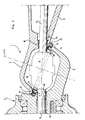
- the structure 1 comprises two cup-shaped bodies 4 and 5, with a first of which is unitary with the axle 2 and the second is unitary with the hub 3.
- the cup-shaped bodies 4 and 5 are arranged to face each other in frontal relationship at the locations of their edges 6 and 7, wherebetween a toroidal seal 9 is inserted.
- the bodies 4 and 5 form, therefore, a sealed cavity 10 which accommodates an equal-velocity joint therein, which is known per se and indicated at 11, to interlink drive shafts 12 and 13 arranged to enter the cavity 10 through respective passageways 14 and 15 which also house respective plain or rolling bearings 16 and 18.
- the face coupling for the cup-shaped bodies 4 and 5 is accomplished, according to the invention, with the intermediary of threadways 19 and 20, the last-mentioned one being formed directly on the free end 7 of the body 5.
- the threadway 19 is instead formed on the inside surface of a ring-like element 21, made of a material having anti-friction properties, specifically bronze, which is made unitary with the end 6 of the cup-shaped body 4.
- the ring-like element 21 is attached to the body 4 by means of screw fasteners 22.
- the axis of the threadways 19 and 20 will define the preset steering axis X-X for the wheel associated with the hub 3.
- the steering action of the wheel connected to the hub 3 will bring about an angular displacement of the cup-shaped body 5 relatively to the cup-shaped body 4 with a movement over their respective threadways 20 and 19 which, for the functional purposes of the structure according to the invention, should not be tightened down together.
- the threadways 19 and 20 will produce axial displacements tending to move the bodies 4 and 5 by a limited amount toward and away from each other, depending, of course, on the pitch length of their respective threadways, but without creating sealing problems within the cavity 10.
- the interfit of the threadways 19 and 20 requires no lubrication because, as previously remarked, at least the threadway 19 is formed on an anti-friction material.
- threadways 19 and 20 allow the loads to be distributed over quite a large surface, with attendant advantages from the standpoints of strength and durability.
- the structure of this invention is also advantageous from an economical standpoint, since it only comprises a few mechanical parts and can do with a much simplified assembly procedure over that incorporating rolling means for forming the steering axis which are inter alia made usually of materials apt to become rusty.
Landscapes
- Engineering & Computer Science (AREA)
- Chemical & Material Sciences (AREA)
- Combustion & Propulsion (AREA)
- Transportation (AREA)
- Mechanical Engineering (AREA)
- Tires In General (AREA)
- Arrangement And Driving Of Transmission Devices (AREA)
- Automatic Cycles, And Cycles In General (AREA)
- Steering-Linkage Mechanisms And Four-Wheel Steering (AREA)
Claims (6)
- Structure de joint entre un essieu (2) et les moyeux (3) des roues motrices et directrices, destinée en particulier aux tracteurs agricoles, qui comprend deux corps (4, 5) en forme de cuvette qui sont respectivement solidaires, l'un de l'essieu et l'autre du moyeu et sont accouplés face à face frontalement le long de leurs bords des moyens d'accouplement de face étant prévus sur les bords pour accoupler lesdit s corps (4, 5) l' un à l' autre dans des positions relatives permettant la rotation relative autour de l'axe de braquage de la roue, lesdits corps en forme de cuvette définissant à l'intérieur une cavité étanche (10) à travers laquelle passent les moyens d'entraînement menant aux moyeux (11), caractérisée en ce que lesdits moyens d'accouplement face à face pour lesdits corps en forme de cuvette sont formés par des filetages hélicoidaux (19, 20) portés par lesdits corps, l'axe (X-X) des filetages coincidant avec l'axe de braquage de la roue.
- Structure selon la revendication 1, caractérisée en ce que le filetage porté par au moins l'un desdits corps en forme de cuvette (4, 5) est formé sur un élément annulaire (21) monté sur le bord du corps en forme de cuvette (4) respectif et fixé sur ce bord.
- Structure selon la revendication 2, caractérisé en ce que ledit élément fileté annulaire (21) est monté et fixé sur le corps en forme de cuvette (4) qui est solidaire de l'essieu (2).
- Structure selon les revendications 1 à 3, caractérisée en ce que ledit élément fileté annulaire (21) monté sur le bord d'au moins un des éléments en forme de cuvette est composé d'une matière ayant des qualités anti-friction.
- Structure selon la revendication 4, caractérisée en ce que ladite matière ayant des qualités anti-friction est le bronze.
- Structure selon une ou plusieurs des revendications précédentes, caractérisé en ce qu'elle comprend des moyens d'étanchéité (9) interposés entre lesdits corps en forme de cuvette (4, 5) au droit desdits filetages (19, 20).
Priority Applications (1)
| Application Number | Priority Date | Filing Date | Title |
|---|---|---|---|
| AT90124425T ATE96383T1 (de) | 1990-05-11 | 1990-12-17 | Verbindung einer angetriebenen lenkbaren radnabe mit einer achse, insbesondere fuer landwirtschaft. |
Applications Claiming Priority (2)
| Application Number | Priority Date | Filing Date | Title |
|---|---|---|---|
| IT41595A IT1239199B (it) | 1990-05-11 | 1990-05-11 | Struttura di collegamento fra assale e mozzo di ruote motrici sterzanti, particolarmente per trattrici agricole |
| IT4159590 | 1990-05-11 |
Publications (2)
| Publication Number | Publication Date |
|---|---|
| EP0455881A1 EP0455881A1 (fr) | 1991-11-13 |
| EP0455881B1 true EP0455881B1 (fr) | 1993-10-27 |
Family
ID=11251741
Family Applications (1)
| Application Number | Title | Priority Date | Filing Date |
|---|---|---|---|
| EP90124425A Expired - Lifetime EP0455881B1 (fr) | 1990-05-11 | 1990-12-17 | Assemblage pour joindre un moyeu de roue entraînable et dirigeable à un essieu, notamment pour l'agriculture |
Country Status (7)
| Country | Link |
|---|---|
| US (1) | US5181885A (fr) |
| EP (1) | EP0455881B1 (fr) |
| JP (1) | JPH06179304A (fr) |
| AT (1) | ATE96383T1 (fr) |
| BR (1) | BR9101218A (fr) |
| DE (1) | DE69004247T2 (fr) |
| IT (1) | IT1239199B (fr) |
Families Citing this family (2)
| Publication number | Priority date | Publication date | Assignee | Title |
|---|---|---|---|---|
| TW364409U (en) * | 1997-08-11 | 1999-07-11 | Work Tools Inc | A double universal joint angle driving assembly |
| US20040124696A1 (en) * | 2002-11-20 | 2004-07-01 | Brunner Drilling And Manufacturing Inc. | Dust cup and wheel spindle |
Family Cites Families (8)
| Publication number | Priority date | Publication date | Assignee | Title |
|---|---|---|---|---|
| US1880098A (en) * | 1930-07-01 | 1932-09-27 | Nat Electric Prod Corp | Swivel connecter fitting for conduits and the like |
| US4026124A (en) * | 1974-07-22 | 1977-05-31 | Kuboto Tekko Kabushiki Kaisha | Case for axle having universal joint |
| US4091689A (en) * | 1976-09-01 | 1978-05-30 | Dana Corporation | Planetary steering hub assembly |
| DE2922660C2 (de) * | 1979-06-02 | 1985-04-04 | Zahnradfabrik Friedrichshafen Ag, 7990 Friedrichshafen | Getriebene Lenkachse |
| JPS5894634A (ja) * | 1981-11-30 | 1983-06-04 | Ishikawajima Shibaura Kikai Kk | 自在継手のシ−ルカバ−装置 |
| GB2155414B (en) * | 1984-03-03 | 1987-06-24 | Gkn Axles | Motor vehicle driving and steering axle |
| JPS62175265A (ja) * | 1986-01-30 | 1987-07-31 | Isuzu Motors Ltd | アクスルエンドのジヨイント構造 |
| DE3763298D1 (de) * | 1986-01-30 | 1990-07-26 | Isuzu Motors Ltd | Gelenkkonstruktion fuer achsgehaeuse mit kugelende. |
-
1990
- 1990-05-11 IT IT41595A patent/IT1239199B/it active IP Right Grant
- 1990-12-17 DE DE90124425T patent/DE69004247T2/de not_active Expired - Fee Related
- 1990-12-17 AT AT90124425T patent/ATE96383T1/de active
- 1990-12-17 EP EP90124425A patent/EP0455881B1/fr not_active Expired - Lifetime
-
1991
- 1991-02-01 JP JP3031347A patent/JPH06179304A/ja active Pending
- 1991-02-11 US US07/653,532 patent/US5181885A/en not_active Expired - Fee Related
- 1991-03-27 BR BR919101218A patent/BR9101218A/pt not_active IP Right Cessation
Also Published As
| Publication number | Publication date |
|---|---|
| US5181885A (en) | 1993-01-26 |
| DE69004247D1 (de) | 1993-12-02 |
| IT9041595A0 (it) | 1990-05-11 |
| JPH06179304A (ja) | 1994-06-28 |
| DE69004247T2 (de) | 1994-03-03 |
| IT1239199B (it) | 1993-09-28 |
| BR9101218A (pt) | 1991-11-26 |
| EP0455881A1 (fr) | 1991-11-13 |
| IT9041595A1 (it) | 1991-11-11 |
| ATE96383T1 (de) | 1993-11-15 |
Similar Documents
| Publication | Publication Date | Title |
|---|---|---|
| US5421591A (en) | Sealing arrangement | |
| EP0890039B1 (fr) | Couplage mecanique presentant une contrainte axiale et radiale elastique avec liberte de torsion, destine en particulier aux pivots et suspensions elastiques et dispositifs similaires | |
| US4364443A (en) | Suspension apparatus for track-type vehicles | |
| CN101734279A (zh) | 电子助力转向装置中的减速器 | |
| US2998735A (en) | Drive axle gearing assembly | |
| US5878832A (en) | Steering apparatus for motor vehicle | |
| US4274338A (en) | Transversely adjustable suspension system | |
| CA1288457C (fr) | Monture de pivotement | |
| US4667759A (en) | Power transmission device of motor-driven power steering | |
| EP0455881B1 (fr) | Assemblage pour joindre un moyeu de roue entraînable et dirigeable à un essieu, notamment pour l'agriculture | |
| US4827788A (en) | Rack and pinion steering gear | |
| WO1982004297A1 (fr) | Joint a anneaux glissants avec anneau d'etancheite rotatif | |
| US4436515A (en) | Articulation device having a double universal joint and a ball joint unit | |
| US4787645A (en) | System for steering rear wheels of a motor vehicle | |
| GB2318771A (en) | Roll control actuator | |
| DE69005183T2 (de) | Lager mit Dichtung für Antriebswellen in Kraftfahrzeugen. | |
| US3227237A (en) | Steerable driving axle | |
| EP1006015B1 (fr) | Essieu avant pour tracteur ou véhicule à moteur similaire | |
| CN112013091B (zh) | 用于车辆动力转向组件的球式螺母组件的支承件 | |
| US3674105A (en) | Drive axle for wide-track crawler vehicles | |
| EP0152025B1 (fr) | Système de direction à 4 roues directrices pour véhicule | |
| KR920008828B1 (ko) | 차량의 후륜조향장치 | |
| US4807939A (en) | Joint structure for axle | |
| CN1138540A (zh) | 转向盘柱用的万向接头 | |
| EP0701510A1 (fr) | Suspension pour roue de vehicule |
Legal Events
| Date | Code | Title | Description |
|---|---|---|---|
| PUAI | Public reference made under article 153(3) epc to a published international application that has entered the european phase |
Free format text: ORIGINAL CODE: 0009012 |
|
| 17P | Request for examination filed |
Effective date: 19910621 |
|
| AK | Designated contracting states |
Kind code of ref document: A1 Designated state(s): AT BE CH DE DK ES FR GB GR LI LU NL SE |
|
| 17Q | First examination report despatched |
Effective date: 19921214 |
|
| GRAA | (expected) grant |
Free format text: ORIGINAL CODE: 0009210 |
|
| AK | Designated contracting states |
Kind code of ref document: B1 Designated state(s): AT BE CH DE DK ES FR GB GR LI LU NL SE |
|
| PG25 | Lapsed in a contracting state [announced via postgrant information from national office to epo] |
Ref country code: SE Effective date: 19931027 Ref country code: NL Effective date: 19931027 Ref country code: LI Effective date: 19931027 Ref country code: GR Free format text: LAPSE BECAUSE OF FAILURE TO SUBMIT A TRANSLATION OF THE DESCRIPTION OR TO PAY THE FEE WITHIN THE PRESCRIBED TIME-LIMIT Effective date: 19931027 Ref country code: ES Free format text: THE PATENT HAS BEEN ANNULLED BY A DECISION OF A NATIONAL AUTHORITY Effective date: 19931027 Ref country code: DK Effective date: 19931027 Ref country code: CH Effective date: 19931027 Ref country code: BE Effective date: 19931027 Ref country code: AT Effective date: 19931027 |
|
| REF | Corresponds to: |
Ref document number: 96383 Country of ref document: AT Date of ref document: 19931115 Kind code of ref document: T |
|
| REF | Corresponds to: |
Ref document number: 69004247 Country of ref document: DE Date of ref document: 19931202 |
|
| PG25 | Lapsed in a contracting state [announced via postgrant information from national office to epo] |
Ref country code: LU Free format text: LAPSE BECAUSE OF NON-PAYMENT OF DUE FEES Effective date: 19931231 |
|
| REG | Reference to a national code |
Ref country code: CH Ref legal event code: PL |
|
| ET | Fr: translation filed | ||
| NLV1 | Nl: lapsed or annulled due to failure to fulfill the requirements of art. 29p and 29m of the patents act | ||
| PLBE | No opposition filed within time limit |
Free format text: ORIGINAL CODE: 0009261 |
|
| STAA | Information on the status of an ep patent application or granted ep patent |
Free format text: STATUS: NO OPPOSITION FILED WITHIN TIME LIMIT |
|
| 26N | No opposition filed | ||
| PG25 | Lapsed in a contracting state [announced via postgrant information from national office to epo] |
Ref country code: GB Effective date: 19941217 |
|
| GBPC | Gb: european patent ceased through non-payment of renewal fee |
Effective date: 19941217 |
|
| PGFP | Annual fee paid to national office [announced via postgrant information from national office to epo] |
Ref country code: DE Payment date: 20011126 Year of fee payment: 12 |
|
| PGFP | Annual fee paid to national office [announced via postgrant information from national office to epo] |
Ref country code: FR Payment date: 20011228 Year of fee payment: 12 |
|
| PG25 | Lapsed in a contracting state [announced via postgrant information from national office to epo] |
Ref country code: DE Free format text: LAPSE BECAUSE OF NON-PAYMENT OF DUE FEES Effective date: 20030701 |
|
| PG25 | Lapsed in a contracting state [announced via postgrant information from national office to epo] |
Ref country code: FR Free format text: LAPSE BECAUSE OF NON-PAYMENT OF DUE FEES Effective date: 20030901 |
|
| REG | Reference to a national code |
Ref country code: FR Ref legal event code: ST |