EP0456020A1 - Dispositif pour la réalisation machinale de maçonnerie - Google Patents
Dispositif pour la réalisation machinale de maçonnerie Download PDFInfo
- Publication number
- EP0456020A1 EP0456020A1 EP91106303A EP91106303A EP0456020A1 EP 0456020 A1 EP0456020 A1 EP 0456020A1 EP 91106303 A EP91106303 A EP 91106303A EP 91106303 A EP91106303 A EP 91106303A EP 0456020 A1 EP0456020 A1 EP 0456020A1
- Authority
- EP
- European Patent Office
- Prior art keywords
- conveyor belt
- block layer
- turning
- wall
- turning table
- Prior art date
- Legal status (The legal status is an assumption and is not a legal conclusion. Google has not performed a legal analysis and makes no representation as to the accuracy of the status listed.)
- Granted
Links
- 238000004519 manufacturing process Methods 0.000 claims abstract description 11
- 238000005304 joining Methods 0.000 claims abstract description 6
- 239000004575 stone Substances 0.000 claims description 15
- 239000011449 brick Substances 0.000 abstract description 5
- 238000006073 displacement reaction Methods 0.000 abstract description 2
- 238000009434 installation Methods 0.000 description 4
- 239000004570 mortar (masonry) Substances 0.000 description 4
- 238000010276 construction Methods 0.000 description 3
- 229910052602 gypsum Inorganic materials 0.000 description 2
- 239000010440 gypsum Substances 0.000 description 2
- 239000000463 material Substances 0.000 description 2
- 238000000034 method Methods 0.000 description 2
- 230000002787 reinforcement Effects 0.000 description 2
- 238000003860 storage Methods 0.000 description 2
- 230000007613 environmental effect Effects 0.000 description 1
- 238000001125 extrusion Methods 0.000 description 1
- 238000009415 formwork Methods 0.000 description 1
- 238000003780 insertion Methods 0.000 description 1
- 230000037431 insertion Effects 0.000 description 1
- 239000011470 perforated brick Substances 0.000 description 1
- 238000009417 prefabrication Methods 0.000 description 1
- 238000002360 preparation method Methods 0.000 description 1
- 230000000717 retained effect Effects 0.000 description 1
- 239000000725 suspension Substances 0.000 description 1
- 230000007704 transition Effects 0.000 description 1
- XLYOFNOQVPJJNP-UHFFFAOYSA-N water Substances O XLYOFNOQVPJJNP-UHFFFAOYSA-N 0.000 description 1
Images

Classifications
-
- E—FIXED CONSTRUCTIONS
- E04—BUILDING
- E04C—STRUCTURAL ELEMENTS; BUILDING MATERIALS
- E04C2/00—Building elements of relatively thin form for the construction of parts of buildings, e.g. sheet materials, slabs, or panels
- E04C2/02—Building elements of relatively thin form for the construction of parts of buildings, e.g. sheet materials, slabs, or panels characterised by specified materials
- E04C2/04—Building elements of relatively thin form for the construction of parts of buildings, e.g. sheet materials, slabs, or panels characterised by specified materials of concrete or other stone-like material; of asbestos cement; of cement and other mineral fibres
- E04C2/041—Building elements of relatively thin form for the construction of parts of buildings, e.g. sheet materials, slabs, or panels characterised by specified materials of concrete or other stone-like material; of asbestos cement; of cement and other mineral fibres composed of a number of smaller elements, e.g. bricks, also combined with a slab of hardenable material
- E04C2/042—Apparatus for handling the smaller elements or the hardenable material; bricklaying machines for prefabricated panels
-
- E—FIXED CONSTRUCTIONS
- E04—BUILDING
- E04G—SCAFFOLDING; FORMS; SHUTTERING; BUILDING IMPLEMENTS OR AIDS, OR THEIR USE; HANDLING BUILDING MATERIALS ON THE SITE; REPAIRING, BREAKING-UP OR OTHER WORK ON EXISTING BUILDINGS
- E04G21/00—Preparing, conveying, or working-up building materials or building elements in situ; Other devices or measures for constructional work
- E04G21/14—Conveying or assembling building elements
- E04G21/16—Tools or apparatus
- E04G21/22—Tools or apparatus for setting building elements with mortar, e.g. bricklaying machines
Definitions
- the invention relates to a system for mechanical masonry production with a turning device, which picks up several blocks intended for arrangement within a block layer, taking mutual distances into account, holds together, pivots around a horizontal axis running parallel to the wall to be produced, and is offset with the top down .
- a turning device of this type is known from German patent 35 20 788.
- This single device is essentially loaded by hand.
- the worker takes the building blocks individually from the supplied pallet using a special lifting device and thus assembles the building block row on the turning table that serves as a turning device. If masonry openings have to be provided, the distances between the stones are measured. Other stones are, according to the laying plan, by means of a Stone saw cut.
- the disadvantage here is that the turning table has to stand still during the time the block layer is being joined; the time to move a row of blocks is thus added up from the assembly time and the turn and travel time.
- the invention has for its object to accelerate the manufacture of masonry slabs with such a device and also to create a system for the rational processing of the masonry slabs produced.
- this object is achieved according to the invention in that a stationary device for joining the block layer and a transfer device for jointly shifting the prepared block layer onto the turning device are provided.
- the assembly and the displacement are decoupled in time, i. H. the corresponding devices can work at least partially at the same time, which increases their degree of utilization and increases the performance of the system.
- the transfer device is integrated in the turning device by this being designed as a clamping frame which extends from above around the prepared block layer.
- the frame takes the place of the turntable on which the blocks must be placed.
- the frame on the other hand, can hold the building blocks on its underside and deliver it on its top, which lies below when turned. It may be necessary to slide and drive the clamping frame in the radial direction within the supporting structure, which connects it to the turning shaft.
- the transfer device is a height-adjustable turning table equipped with clamping devices, which picks up the prepared block layer, pivots and pivots back after setting the correct height and sets it down on a second turning table, which in turn builds up the wall.
- the device for assembling the block layer will preferably be arranged so that it is located under the second turning table in the loading position.
- the axis of the first turning table runs and moves in a parallel plane to the wall to be produced, which is however further away from this wall than the axis of the second turning table.
- the turning tables are controlled in such a way that the first turning table receiving the block layer is first pivoted out of the range of motion of the second turning table. Then the first turning table moves up or the second turning table so far down that the transfer of the block layer can take place.
- the device for joining the block layer preferably comprises a conveyor belt which is program-controlled in steps and a program-controlled stone layer which picks up the blocks one after the other from a supply and in the same position at the same place on the conveyor belt.
- the conveyor belt then moves a stone length or an additional length if a masonry opening is to be formed.
- a stone saw that can be moved in program-controlled manner is provided in order to shorten a building block placed on the conveyor belt if necessary.
- the building block to be shortened can be conveyed from the conveyor belt to the stone saw and back again by means of a turning device, the sawn-off and unnecessary part of the building block being ejected laterally. All of these processes can be controlled with the aid of drive devices known per se according to an individual program which is set up in the course of work preparation on the basis of the construction plan.
- a further decisive rationalization step with this individually planned prefabricated construction method is that the wall disks are created on trolleys that can be transported in a round trip through several expansion stations. It is advantageous if the transport carts can be rotated carousel-like by 180 °, so that two parallel walls can be created on them by means of a stationary wall machine. In a first expansion station, the walls should be provided with the necessary transport scaffolding or suspension reinforcement. In the further expansion stations one has to think of the individual building trades, e.g. B. on the insertion of the windows, the installation of parts of the electrical and water installation, the plastering of the wall surfaces, the installation of the shutters u. The like. Substantial savings in working time are achieved because the mechanics do not have to drive to changing workplaces.
- the material transport is omitted, since the material stores are provided along the circular route of the transport carts.
- the working conditions are much better since there is no physical work, the risk of accidents is reduced and the environmental conditions (heated hall) can be better. Nevertheless, the proposed individual system, the individual planning and the use of different wall thicknesses and building blocks, can be retained through the proposed system.
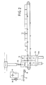
- Fig. 1 shows on the left a started wall disc 1 in front view and on the right thereof two double pillars 2 and 3, which belong to two portal scaffolds, in which the horizontal shafts 4 and 5 of two turning tables 6 and 7 are vertically movable and rotatably received. The individual travel and swivel drives of the turning tables are not shown. Between the double pillars 2 and 3 and in terms of height below the wall support surface 8, which can be designed as a trolley according to FIG. 4, there is a horizontal conveyor belt 9 which, like the shafts 4 and 5, extends parallel to the wall disk 1.
- the turning tables 6 and 7 have schematically indicated clamping devices, each consisting of a stop bar 10 fastened to the turning table and radially movable clamping bars 11, which hold a number of blocks 12 placed one behind the other, which form a block layer to be moved together, lying or hanging on the relevant turning table.
- FIG. 1 also shows a mortar dispenser 13 moving back and forth at the desired height above the wall crown.
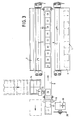
- FIGS. 2 and 3 show in particular the assembly device for the block layer.
- the conveyor belt on the end face of the wall disk 1, there is the parking space of a pallet 14, from which the delivered blocks are removed by means of a gripper 15 and placed individually on the conveyor belt 9 at the front.
- the gripper works like a robot with fully automatic electronic control, which is possible insofar as each pallet contains the same number of building blocks in the same arrangement.
- These are preferably perforated bricks which have at least one larger opening 16 in the direction of extrusion into which the gripper pushes and goes spreads.
- the module is then turned by the gripper by 90 ° and placed on the conveyor belt 9 with the opening 16 facing upwards.
- the pallet lies on a lifting table 16a which, after clearing off one block layer, moves up one block height.
- the full pallets are conveyed to one side and the empty pallets are removed at right angles to them.
- a smaller turning device with a turning table 17 and a horizontal shaft 18 running transversely to the conveyor belt 9.
- This turning device serves, if provided according to the construction plan, to remove a building block from the placement point at the beginning of the conveyor belt and after that To turn by 180 ° in the area of a stone saw 19, the saw blade of which is designated 20.
- the stone saw's direction of advance during sawing runs across the conveyor belt.
- the entire saw can be adjusted on a corresponding slide in the direction of the conveyor belt in a program-controlled manner by precisely definable lengths.
- the clamping devices, not shown, on the turning table 17 move transversely to the conveyor belt, that is to say in the direction of the turning shaft 18.
- the remaining shortened stone can be securely held regardless of its length after the sawing process and can be put back on the conveyor belt 9.
- the block must also be held on the turning table 17 in such a way that the saw blade is not hindered.
- the above-mentioned clamping device must dip down. Another device, not shown, pushes the separated and unnecessary part of the module from the turning table 17 and conveys it away.
- the first block layer assembled on the conveyor belt 9 is picked up by the turning table 7 by pivoting to the left and lying on the block layer, after which its clamping device 10, 11 closes. Thereafter, the turning table 7 pivots so far to the right and moves so far up that the turning table 6 can pivot into its right position, in which its receiving surface is turned upwards, and can possibly move a bit downwards.
- the conveyor belt 9 is, however, loaded again immediately after reaching its unloading position. When the turntable 6 has reached the position shown in solid lines and the turntable 7 is next to it by one block height, the transfer can take place.
- the turning table 7 pivots to the left and places the block layer on the turning table 6.
- the clamping device of the turning table 6 closes and that of the turning table 7 opens.
- the turning table 6 swivels 180 ° to the left and moves so far down that the hanging building block layer is deposited on the support surface 8.
- a mortar bed has previously been prepared on this by means of the mortar dispenser 13.
- the turning table 6 then swivels back again by 180 ° and moves so far up that the turning table 7, which has meanwhile been moved downwards, becomes the next, now unimpeded can pick up assembled block layer. This is shifted layer by layer until the wall disc 1 is finished and can be removed.
- a precise program control of the individual motion sequences ensures their timing coordination and guarantees uninterrupted work of all components, which ultimately leads to an extraordinarily high production speed.
- the program also determines the height at which the transfer of the building block layer from the turning table 7 to the turning table 6 is to take place. This can be an unchanged position at medium height, as indicated in FIG. 1. However, the transfer can also take place at different heights, so that after the transfer of the turning table 6 for moving the row of blocks on the wall, no longer has to travel a great distance in the height direction.
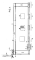
- the expanded production system according to FIG. 4 has a rectangular track system 21, which individual transport carriages 22 preferably travel in the direction of the arrow in the circulation.
- the wheels of the transport trolleys can be swiveled around vertical axes and are swiveled by 90 ° during the transition from the narrow sides of the rectangle to the long sides or vice versa.
- the support tables of the trolleys 22 can be swiveled carousel-like on the base frames between two opposite positions. In this way, it is possible to create two wall disks on a transport carriage 22 by means of the wall production plant, which is designated 23 in this figure.
- the transport carriage 22 Since this system is stationary, the transport carriage 22 is moved a little way after the first wall disk has been completed and is moved back to the system after the table has been rotated through 180 °.
- the subsequent track section with a large track width serves as Storage space for several transport trolleys with finished wall panels.
- a first station 24 vertical reinforcement bars are introduced and poured with concrete, which ensure the transportability of the wall pane and z. B. provide attachment points for the crane eyes.
- stationary work scaffolding 25 can be provided in order to enable comfortable work.
- the concrete straps required for some wall washers are applied.
- the bearing for the necessary formwork is designated 27.
- windows are used and, if necessary, electrical and sanitary installations are attached.
- a window bearing is designated 28.
- the wall surfaces are plastered, in particular plastered, for which purpose the wall pane is advantageously brought into a horizontal position.
- the receiving and swivel tables required for this can be provided in this station.
- a gypsum store is designated 30.
- the roller shutters are finally installed in a fifth station 31.
Landscapes
- Engineering & Computer Science (AREA)
- Architecture (AREA)
- Civil Engineering (AREA)
- Structural Engineering (AREA)
- Mechanical Engineering (AREA)
- Processing Of Stones Or Stones Resemblance Materials (AREA)
- Conveying And Assembling Of Building Elements In Situ (AREA)
- Devices For Post-Treatments, Processing, Supply, Discharge, And Other Processes (AREA)
- Attitude Control For Articles On Conveyors (AREA)
- Specific Conveyance Elements (AREA)
- Pretreatment Of Seeds And Plants (AREA)
Applications Claiming Priority (2)
| Application Number | Priority Date | Filing Date | Title |
|---|---|---|---|
| DE4014615A DE4014615A1 (de) | 1990-05-07 | 1990-05-07 | Anlage zur maschinellen mauerwerksfertigung |
| DE4014615 | 1990-05-07 |
Publications (2)
| Publication Number | Publication Date |
|---|---|
| EP0456020A1 true EP0456020A1 (fr) | 1991-11-13 |
| EP0456020B1 EP0456020B1 (fr) | 1995-01-25 |
Family
ID=6405880
Family Applications (1)
| Application Number | Title | Priority Date | Filing Date |
|---|---|---|---|
| EP91106303A Expired - Lifetime EP0456020B1 (fr) | 1990-05-07 | 1991-04-19 | Dispositif pour la réalisation machinale de maçonnerie |
Country Status (5)
| Country | Link |
|---|---|
| US (1) | US5199412A (fr) |
| EP (1) | EP0456020B1 (fr) |
| AT (1) | ATE117760T1 (fr) |
| DE (2) | DE4014615A1 (fr) |
| RU (1) | RU2019655C1 (fr) |
Cited By (14)
| Publication number | Priority date | Publication date | Assignee | Title |
|---|---|---|---|---|
| EP0872609A2 (fr) | 1997-04-14 | 1998-10-21 | Augustin Dipl.-Ing. Heuberger | Méthode de fabrication d' un panneau multicouche |
| ES2296556A1 (es) * | 2007-07-16 | 2008-04-16 | Pablo Germade Castiñeiras | Maquina automatica para la formacion de muros de fabrica por hiladas. |
| CN102162302A (zh) * | 2011-04-08 | 2011-08-24 | 浙江东南网架股份有限公司 | 一种大型钢构件加工制作的翻身装置 |
| CN108086700A (zh) * | 2017-12-19 | 2018-05-29 | 谭增红 | 一种用于建筑施工的自动砌砖墙装置 |
| US10635758B2 (en) | 2016-07-15 | 2020-04-28 | Fastbrick Ip Pty Ltd | Brick/block laying machine incorporated in a vehicle |
| US10865578B2 (en) | 2016-07-15 | 2020-12-15 | Fastbrick Ip Pty Ltd | Boom for material transport |
| US11401115B2 (en) | 2017-10-11 | 2022-08-02 | Fastbrick Ip Pty Ltd | Machine for conveying objects and multi-bay carousel for use therewith |
| US11441899B2 (en) | 2017-07-05 | 2022-09-13 | Fastbrick Ip Pty Ltd | Real time position and orientation tracker |
| CN117226982A (zh) * | 2023-10-19 | 2023-12-15 | 绍兴绿展环保有限公司 | 一种墙板部品的孔槽面修整生产线及其修整工艺 |
| US11958193B2 (en) | 2017-08-17 | 2024-04-16 | Fastbrick Ip Pty Ltd | Communication system for an interaction system |
| US12214500B2 (en) | 2018-07-16 | 2025-02-04 | Fastbrick Ip Pty Ltd | Backup tracking for an interaction system |
| US12311546B2 (en) | 2018-07-16 | 2025-05-27 | Fastbrick Ip Pty Ltd | Active damping system |
| US12385265B2 (en) | 2020-04-22 | 2025-08-12 | Fastbrick Ip Pty Ltd | Block transfer apparatus and improved clamping assembly for use therewith |
| US12398574B2 (en) | 2020-07-08 | 2025-08-26 | Fastbrick Ip Pty Ltd | Adhesive application system |
Families Citing this family (5)
| Publication number | Priority date | Publication date | Assignee | Title |
|---|---|---|---|---|
| RU2464392C1 (ru) * | 2011-05-25 | 2012-10-20 | Виктор Михайлович Бельфор | Способ возведения стен, установка для автоматизированного возведения стен из строительных модулей и комплект оборудования для механизированного возведения стен из строительных модулей |
| RU2606886C1 (ru) * | 2015-12-14 | 2017-01-10 | Павел Степанович Тигунцев | Автоматизированный способ возведения зданий из строительных блоков |
| CN106917512A (zh) * | 2015-12-28 | 2017-07-04 | 天津亚斯德瑞科技发展有限公司 | 一种多用建材循环轨道 |
| ES2831111A1 (es) * | 2019-12-05 | 2021-06-07 | Martos Maria Dolores Marin | Sistema automatizado de tratamiento de materia prima |
| CN113073865B (zh) * | 2021-03-18 | 2025-02-07 | 安徽金煌建设集团有限公司 | 一种建筑填充墙砌块砌筑设备 |
Citations (6)
| Publication number | Priority date | Publication date | Assignee | Title |
|---|---|---|---|---|
| FR2113012A5 (fr) * | 1970-10-06 | 1972-06-23 | Lingl Hans | |
| DE3520788A1 (de) * | 1985-06-10 | 1986-12-11 | Anton 7940 Riedlingen Anliker | Verfahren und vorrichtung zum mauern von wandscheiben aus bausteinen |
| DE3601404A1 (de) * | 1986-01-18 | 1987-07-23 | Anton Anliker | Vorrichtung zum versetzen von bausteinen, insbesondere hochlochziegeln |
| DE3712847A1 (de) * | 1987-04-15 | 1988-11-03 | Albert Wager | Verfahren und einrichtung zum maschinellen mauern von waenden aus bausteinen |
| DE3722244A1 (de) * | 1987-07-06 | 1989-01-19 | Michael Hering | Vorrichtung zur herstellung von waenden aus mauerwerk |
| DE3523924C1 (de) * | 1985-07-04 | 1992-09-24 | SÜBA-Cooperation Gesellschaft für Bauforschung, Bauentwicklung und Franchising mbH, 6832 Hockenheim | Verfahren und Vorrichtung zur Herstellung vorgefertigter Wandelemente aus Mauersteinen |
Family Cites Families (8)
| Publication number | Priority date | Publication date | Assignee | Title |
|---|---|---|---|---|
| AT253200B (de) * | 1965-03-15 | 1967-03-28 | Josef Waha | Verfahren und Vorrichtung zur Herstellung von Mauerwerk aus Bausteinen |
| NL6814998A (fr) * | 1967-10-20 | 1969-04-22 | ||
| US3936333A (en) * | 1971-10-26 | 1976-02-03 | Masonry Systems International, Inc. | Method for prefabricating brick panels |
| DE2233205A1 (de) * | 1972-07-06 | 1974-03-14 | Siegfried Dipl Phys Drosdziok | Parametrischer verstaerker und oszillator fuer mechanische schwingungen |
| US3930929A (en) * | 1972-11-03 | 1976-01-06 | Lingl Corporation | Apparatus to construct wall panels having openings for doors and windows |
| DE2531957C3 (de) * | 1975-07-17 | 1982-04-08 | Hans Lingl Anlagenbau Und Verfahrenstechnik Gmbh & Co Kg, 7910 Neu-Ulm | Verfahren zur automatischen Vorfertigung von Wandteilen aus Blockziegeln o.dgl. |
| DE3313731C2 (de) * | 1982-11-20 | 1985-09-05 | Rheiner Maschinenfabrik Windhoff Ag, 4440 Rheine | Verfahren zum maschinellen Herstellen von Wandelementen |
| EP0221852A3 (fr) * | 1985-11-07 | 1988-11-23 | Fritz Haug AG | Dispositif pour travailler des matériaux relativement durs |
-
1990
- 1990-05-07 DE DE4014615A patent/DE4014615A1/de not_active Withdrawn
-
1991
- 1991-04-19 DE DE59104360T patent/DE59104360D1/de not_active Expired - Fee Related
- 1991-04-19 AT AT91106303T patent/ATE117760T1/de not_active IP Right Cessation
- 1991-04-19 EP EP91106303A patent/EP0456020B1/fr not_active Expired - Lifetime
- 1991-05-01 US US07/693,294 patent/US5199412A/en not_active Expired - Fee Related
- 1991-05-06 RU SU914895290A patent/RU2019655C1/ru active
Patent Citations (6)
| Publication number | Priority date | Publication date | Assignee | Title |
|---|---|---|---|---|
| FR2113012A5 (fr) * | 1970-10-06 | 1972-06-23 | Lingl Hans | |
| DE3520788A1 (de) * | 1985-06-10 | 1986-12-11 | Anton 7940 Riedlingen Anliker | Verfahren und vorrichtung zum mauern von wandscheiben aus bausteinen |
| DE3523924C1 (de) * | 1985-07-04 | 1992-09-24 | SÜBA-Cooperation Gesellschaft für Bauforschung, Bauentwicklung und Franchising mbH, 6832 Hockenheim | Verfahren und Vorrichtung zur Herstellung vorgefertigter Wandelemente aus Mauersteinen |
| DE3601404A1 (de) * | 1986-01-18 | 1987-07-23 | Anton Anliker | Vorrichtung zum versetzen von bausteinen, insbesondere hochlochziegeln |
| DE3712847A1 (de) * | 1987-04-15 | 1988-11-03 | Albert Wager | Verfahren und einrichtung zum maschinellen mauern von waenden aus bausteinen |
| DE3722244A1 (de) * | 1987-07-06 | 1989-01-19 | Michael Hering | Vorrichtung zur herstellung von waenden aus mauerwerk |
Cited By (29)
| Publication number | Priority date | Publication date | Assignee | Title |
|---|---|---|---|---|
| EP0872609A2 (fr) | 1997-04-14 | 1998-10-21 | Augustin Dipl.-Ing. Heuberger | Méthode de fabrication d' un panneau multicouche |
| AT409395B (de) * | 1997-04-14 | 2002-07-25 | Augustin Dipl Ing Heuberger | Verfahren zur herstellung mehrschaliger mauerscheiben |
| ES2296556A1 (es) * | 2007-07-16 | 2008-04-16 | Pablo Germade Castiñeiras | Maquina automatica para la formacion de muros de fabrica por hiladas. |
| ES2296556B1 (es) * | 2007-07-16 | 2009-08-18 | Pablo Germade Castiñeiras | Maquina automatica para la formacion de muros de fabrica por hiladas. |
| CN102162302A (zh) * | 2011-04-08 | 2011-08-24 | 浙江东南网架股份有限公司 | 一种大型钢构件加工制作的翻身装置 |
| CN102162302B (zh) * | 2011-04-08 | 2012-07-04 | 浙江东南网架股份有限公司 | 一种大型钢构件加工制作的翻身装置 |
| US11687686B2 (en) | 2016-07-15 | 2023-06-27 | Fastbrick Ip Pty Ltd | Brick/block laying machine incorporated in a vehicle |
| US12197820B2 (en) | 2016-07-15 | 2025-01-14 | Fastbrick Ip Pty Ltd | Virtual robot base |
| US10865578B2 (en) | 2016-07-15 | 2020-12-15 | Fastbrick Ip Pty Ltd | Boom for material transport |
| US10876308B2 (en) | 2016-07-15 | 2020-12-29 | Fastbrick Ip Pty Ltd | Boom for material transport |
| US11106836B2 (en) | 2016-07-15 | 2021-08-31 | Fastbrick Ip Pty Ltd | Brick/block laying machine incorporated in a vehicle |
| US11299894B2 (en) | 2016-07-15 | 2022-04-12 | Fastbrick Ip Pty Ltd | Boom for material transport |
| US12353801B2 (en) | 2016-07-15 | 2025-07-08 | Fastbrick Ip Pty Ltd | Robot base path planning |
| US12073150B2 (en) | 2016-07-15 | 2024-08-27 | Fastbrick Ip Pty Ltd | Dynamic path for end effector control |
| US12210803B2 (en) | 2016-07-15 | 2025-01-28 | Fastbrick Ip Pty Ltd | Robot arm kinematics for end effector control |
| US11842124B2 (en) | 2016-07-15 | 2023-12-12 | Fastbrick Ip Pty Ltd | Dynamic compensation of a robot arm mounted on a flexible arm |
| US12175164B2 (en) | 2016-07-15 | 2024-12-24 | Fastbrick Ip Pty Ltd | Path correction for end effector control |
| US10635758B2 (en) | 2016-07-15 | 2020-04-28 | Fastbrick Ip Pty Ltd | Brick/block laying machine incorporated in a vehicle |
| US12001761B2 (en) | 2016-07-15 | 2024-06-04 | Fastbrick Ip Pty Ltd | Computer aided design for brick and block constructions and control software to control a machine to construct a building |
| US11441899B2 (en) | 2017-07-05 | 2022-09-13 | Fastbrick Ip Pty Ltd | Real time position and orientation tracker |
| US11958193B2 (en) | 2017-08-17 | 2024-04-16 | Fastbrick Ip Pty Ltd | Communication system for an interaction system |
| US12569988B2 (en) | 2017-08-17 | 2026-03-10 | Fastbrick Ip Pty Ltd | Communication system for an interaction system |
| US11401115B2 (en) | 2017-10-11 | 2022-08-02 | Fastbrick Ip Pty Ltd | Machine for conveying objects and multi-bay carousel for use therewith |
| CN108086700A (zh) * | 2017-12-19 | 2018-05-29 | 谭增红 | 一种用于建筑施工的自动砌砖墙装置 |
| US12214500B2 (en) | 2018-07-16 | 2025-02-04 | Fastbrick Ip Pty Ltd | Backup tracking for an interaction system |
| US12311546B2 (en) | 2018-07-16 | 2025-05-27 | Fastbrick Ip Pty Ltd | Active damping system |
| US12385265B2 (en) | 2020-04-22 | 2025-08-12 | Fastbrick Ip Pty Ltd | Block transfer apparatus and improved clamping assembly for use therewith |
| US12398574B2 (en) | 2020-07-08 | 2025-08-26 | Fastbrick Ip Pty Ltd | Adhesive application system |
| CN117226982A (zh) * | 2023-10-19 | 2023-12-15 | 绍兴绿展环保有限公司 | 一种墙板部品的孔槽面修整生产线及其修整工艺 |
Also Published As
| Publication number | Publication date |
|---|---|
| DE4014615A1 (de) | 1991-11-14 |
| DE59104360D1 (de) | 1995-03-09 |
| EP0456020B1 (fr) | 1995-01-25 |
| ATE117760T1 (de) | 1995-02-15 |
| US5199412A (en) | 1993-04-06 |
| RU2019655C1 (ru) | 1994-09-15 |
Similar Documents
| Publication | Publication Date | Title |
|---|---|---|
| EP0456020B1 (fr) | Dispositif pour la réalisation machinale de maçonnerie | |
| AT506747B1 (de) | Verfahren zur herstellung von betonfertigbauelementen, bei dem die herstellung der bauelemente auf palettenformen erfolgt | |
| EP0674069B1 (fr) | Méthode et dispositif pour la réalisation de constructions avec l'emploi de briques de maçonnerie et/ou de coffrages | |
| DE19603234C2 (de) | Vorrichtung zm automatischen Mauern | |
| EP0495525B1 (fr) | Dispositif et procédé pour fabriquer des pièces de mur ou des tableaux muraux à l'aide de pierres de construction | |
| EP0225893B1 (fr) | Procede et dispositif pour construire des sections de parois a l'aide de blocs de construction | |
| DE2334615A1 (de) | Verfahren zur herstellung von raumkaesten fuer fertighaeuser | |
| DE2334646A1 (de) | Verfahren zur herstellung von raumkaesten fuer fertighaeuser | |
| EP2681371B1 (fr) | Procédé de fabrication continue d'éléments de panneau de coffrage composite | |
| DE19509809A1 (de) | Vorrichtung zum Erstellen von Wandungsabschnitten aus Mauerwerk | |
| DE19600006A1 (de) | Verfahren zum weitgehend automatisierten Herstellen von Mauersteinverbänden für Gebäude, Gebäudeteile oder Mauern und Mauerautomat, insbesondere zur Durchführung des Verfahrens | |
| AT253200B (de) | Verfahren und Vorrichtung zur Herstellung von Mauerwerk aus Bausteinen | |
| WO2016198239A1 (fr) | Procédé de fabrication de composants préfabriqués et dispositif de formation de couches destiné à être utilisé dans un tel procédé | |
| EP0536600B1 (fr) | Dispositif pour la fabrication d'armatures | |
| DE2032793C3 (de) | Anlage und Verfahren zum Ein-, Entschalen, Reinigen und Leeren von Formwagen | |
| DE3932810A1 (de) | Vorrichtung zum einbringen einer bewehrung in eine palette mit facheinteilung | |
| DE3722244A1 (de) | Vorrichtung zur herstellung von waenden aus mauerwerk | |
| DE9117259U1 (de) | Vorrichtung zur Erstellung von Bewehrungen | |
| AT403603B (de) | Verfahren und vorrichtung zur herstellung vorgefertigter wandelemente aus mauersteinen | |
| DE9218809U1 (de) | Vorrichtung zum Herstellen von Mauerstücken oder Wandtafeln aus Mauersteinen | |
| DE19756207A1 (de) | Verfahren und Vorrichtung zur Herstellung von Rohgebäude-Verbundbauteilen | |
| DE19858219A1 (de) | Mauermaschine zum Erstellen von Wandelementen aus Bausteinen | |
| DE19813583A1 (de) | Verfahren und Vorrichtung zur Herstellung von Mauerwerk | |
| DE3344034A1 (de) | Anlage zur fliessbandfertigung von betonfertigbauteilen, insbesondere von grosstafeln | |
| DE2213349A1 (de) | Maschine zur maschinellen herstellung von baustein-mauer8erk aus schichtweise und versetzt angeordneten bausteinen |
Legal Events
| Date | Code | Title | Description |
|---|---|---|---|
| PUAI | Public reference made under article 153(3) epc to a published international application that has entered the european phase |
Free format text: ORIGINAL CODE: 0009012 |
|
| AK | Designated contracting states |
Kind code of ref document: A1 Designated state(s): AT CH DE FR IT LI |
|
| 17P | Request for examination filed |
Effective date: 19911216 |
|
| 17Q | First examination report despatched |
Effective date: 19930215 |
|
| GRAA | (expected) grant |
Free format text: ORIGINAL CODE: 0009210 |
|
| AK | Designated contracting states |
Kind code of ref document: B1 Designated state(s): AT CH DE FR IT LI |
|
| REF | Corresponds to: |
Ref document number: 117760 Country of ref document: AT Date of ref document: 19950215 Kind code of ref document: T |
|
| REF | Corresponds to: |
Ref document number: 59104360 Country of ref document: DE Date of ref document: 19950309 |
|
| ET | Fr: translation filed | ||
| ITF | It: translation for a ep patent filed | ||
| PLBE | No opposition filed within time limit |
Free format text: ORIGINAL CODE: 0009261 |
|
| STAA | Information on the status of an ep patent application or granted ep patent |
Free format text: STATUS: NO OPPOSITION FILED WITHIN TIME LIMIT |
|
| 26N | No opposition filed | ||
| PGFP | Annual fee paid to national office [announced via postgrant information from national office to epo] |
Ref country code: FR Payment date: 19980428 Year of fee payment: 8 |
|
| PGFP | Annual fee paid to national office [announced via postgrant information from national office to epo] |
Ref country code: AT Payment date: 19980429 Year of fee payment: 8 |
|
| PGFP | Annual fee paid to national office [announced via postgrant information from national office to epo] |
Ref country code: CH Payment date: 19980501 Year of fee payment: 8 |
|
| PG25 | Lapsed in a contracting state [announced via postgrant information from national office to epo] |
Ref country code: AT Free format text: LAPSE BECAUSE OF NON-PAYMENT OF DUE FEES Effective date: 19990419 |
|
| PG25 | Lapsed in a contracting state [announced via postgrant information from national office to epo] |
Ref country code: LI Free format text: LAPSE BECAUSE OF NON-PAYMENT OF DUE FEES Effective date: 19990430 Ref country code: CH Free format text: LAPSE BECAUSE OF NON-PAYMENT OF DUE FEES Effective date: 19990430 |
|
| PGFP | Annual fee paid to national office [announced via postgrant information from national office to epo] |
Ref country code: DE Payment date: 19990506 Year of fee payment: 9 |
|
| REG | Reference to a national code |
Ref country code: CH Ref legal event code: PL |
|
| PG25 | Lapsed in a contracting state [announced via postgrant information from national office to epo] |
Ref country code: FR Free format text: LAPSE BECAUSE OF NON-PAYMENT OF DUE FEES Effective date: 19991231 |
|
| REG | Reference to a national code |
Ref country code: FR Ref legal event code: ST |
|
| PG25 | Lapsed in a contracting state [announced via postgrant information from national office to epo] |
Ref country code: DE Free format text: LAPSE BECAUSE OF NON-PAYMENT OF DUE FEES Effective date: 20010201 |
|
| PG25 | Lapsed in a contracting state [announced via postgrant information from national office to epo] |
Ref country code: IT Free format text: LAPSE BECAUSE OF NON-PAYMENT OF DUE FEES;WARNING: LAPSES OF ITALIAN PATENTS WITH EFFECTIVE DATE BEFORE 2007 MAY HAVE OCCURRED AT ANY TIME BEFORE 2007. THE CORRECT EFFECTIVE DATE MAY BE DIFFERENT FROM THE ONE RECORDED. Effective date: 20050419 |