EP0456077B1 - Support de gouttières de culture - Google Patents
Support de gouttières de culture Download PDFInfo
- Publication number
- EP0456077B1 EP0456077B1 EP91106943A EP91106943A EP0456077B1 EP 0456077 B1 EP0456077 B1 EP 0456077B1 EP 91106943 A EP91106943 A EP 91106943A EP 91106943 A EP91106943 A EP 91106943A EP 0456077 B1 EP0456077 B1 EP 0456077B1
- Authority
- EP
- European Patent Office
- Prior art keywords
- support
- support according
- rails
- fishplates
- culture
- Prior art date
- Legal status (The legal status is an assumption and is not a legal conclusion. Google has not performed a legal analysis and makes no representation as to the accuracy of the status listed.)
- Expired - Lifetime
Links
- 239000002184 metal Substances 0.000 claims description 6
- 238000003466 welding Methods 0.000 claims description 4
- 241000196324 Embryophyta Species 0.000 description 12
- 230000002262 irrigation Effects 0.000 description 9
- 238000003973 irrigation Methods 0.000 description 9
- XLYOFNOQVPJJNP-UHFFFAOYSA-N water Substances O XLYOFNOQVPJJNP-UHFFFAOYSA-N 0.000 description 9
- 239000003337 fertilizer Substances 0.000 description 4
- 238000004519 manufacturing process Methods 0.000 description 3
- 238000005304 joining Methods 0.000 description 2
- 238000004080 punching Methods 0.000 description 2
- 102000010637 Aquaporins Human genes 0.000 description 1
- 235000004443 Ricinus communis Nutrition 0.000 description 1
- 240000000528 Ricinus communis Species 0.000 description 1
- 230000006978 adaptation Effects 0.000 description 1
- 238000005452 bending Methods 0.000 description 1
- 238000006243 chemical reaction Methods 0.000 description 1
- 230000001419 dependent effect Effects 0.000 description 1
- 238000005516 engineering process Methods 0.000 description 1
- 230000002349 favourable effect Effects 0.000 description 1
- 230000004720 fertilization Effects 0.000 description 1
- 239000000463 material Substances 0.000 description 1
- 238000000034 method Methods 0.000 description 1
- 239000002689 soil Substances 0.000 description 1
Images
Classifications
-
- A—HUMAN NECESSITIES
- A01—AGRICULTURE; FORESTRY; ANIMAL HUSBANDRY; HUNTING; TRAPPING; FISHING
- A01G—HORTICULTURE; CULTIVATION OF VEGETABLES, FLOWERS, RICE, FRUIT, VINES, HOPS OR SEAWEED; FORESTRY; WATERING
- A01G9/00—Cultivation in receptacles, forcing-frames or greenhouses; Edging for beds, lawn or the like
- A01G9/14—Greenhouses
- A01G9/1423—Greenhouse bench structures
-
- Y—GENERAL TAGGING OF NEW TECHNOLOGICAL DEVELOPMENTS; GENERAL TAGGING OF CROSS-SECTIONAL TECHNOLOGIES SPANNING OVER SEVERAL SECTIONS OF THE IPC; TECHNICAL SUBJECTS COVERED BY FORMER USPC CROSS-REFERENCE ART COLLECTIONS [XRACs] AND DIGESTS
- Y02—TECHNOLOGIES OR APPLICATIONS FOR MITIGATION OR ADAPTATION AGAINST CLIMATE CHANGE
- Y02A—TECHNOLOGIES FOR ADAPTATION TO CLIMATE CHANGE
- Y02A40/00—Adaptation technologies in agriculture, forestry, livestock or agroalimentary production
- Y02A40/10—Adaptation technologies in agriculture, forestry, livestock or agroalimentary production in agriculture
- Y02A40/25—Greenhouse technology, e.g. cooling systems therefor
Definitions
- the invention relates to a support for a plurality of cultivation troughs for plants, the supports consisting of horizontal, longitudinal support rails which run transversely to the cultivation troughs and have holding elements which project upwards on their upper side.
- the plants are placed in cultivation troughs for cultivation in greenhouses or outdoors.
- the cultivation channels also serve as irrigation channels.
- water possibly with fertilizer dissolved therein, is added and flows to the lower end of the culture channel. Since the plants are usually placed in plant pots on the bottom of the gutter, the plants absorb the water and the fertilizer. From the lower end of the gutter, the water is pumped back to the upper end of the gutter. This avoids losses and stress on the soil.
- the cultivation channels In a known carrier for cultivation channels of the type mentioned at the beginning (US Pat. No. 4,476,651), in which the plants are placed directly into the cultivation channels without plant pots, the cultivation channels consist of extruded profiles which have ribs pointing downward.
- the support rails forming the support for these cultivation channels are designed as double-T profiles with a lying web surface, the upstanding flanges of which form the holding elements which engage with the lower ribs of the culture channels via incisions. In this way, the cultivation channels are secured against a horizontal shift; but they can be lifted off the mounting rails.
- the object of the invention is to provide a support for a plurality of cultivation channels which, together with the culture channels incorporated therein, forms an easily transportable unit, on which the culture channels are securely and firmly attached and from which the culture channels can also be easily removed if required .
- This object is achieved in that the holding elements as individual, each from the top of the Carrier rail protruding retaining tabs are executed and that each culture gutter is held snapping between two retaining tabs.
- the support rails forming the support for the cultivation channels are relatively light and can also be transported individually and kept ready to save space. Together with the several cultivation channels, each of which is connected to the mounting rails via snap-in connections, a stable, easy-to-transport unit is created that can be easily dismantled if necessary. Since the weight of this unit is only slightly greater than the weight of the fitted culture trays accommodated in it, this unit can be transported with transport devices and placed in rack-like frames.
- the manufacture of the mounting rails is very simple and requires little material.
- the retaining tabs are designed to be resilient in the longitudinal direction of the mounting rails.
- the retaining tabs can also be essentially rigid and the culture channels can be resiliently compressible at least at their upper edges in order to be snapped in between the retaining tabs.
- Two holding tabs opposite each other engage with locking projections that protrude against each other in locking recesses or over the upper edges of the cultivation channels.
- a snap connection between the culture channels and the mounting rails is thus produced in a particularly simple manner. Openings in the side walls of the cultivation channels can be used as recesses, which are punched out there anyway to form retaining tabs for the plant pots.
- existing cultivation channels can also be used for mounting on the mounting rails without the need for adaptation or conversion.
- the mounting rails are preferably each designed as U-rails which are open at the bottom. They can have castors so that the unit consisting of the cultivation channels and the support rails can be moved on the floor or on guide rails of a frame.
- the retaining tabs can be punched out of the upper web surface of the U-shaped mounting rails and bent up. Instead, however, it is also possible for the retaining tabs to be angled upward from a base plate which is connected to the upper side of the mounting rail.
- An embodiment is particularly favorable in terms of production technology, in which two opposing holding straps with a common footplate are designed as a one-piece holding bracket made of sheet metal, which on the web surface of the mounting rail is fastened, for example, by means of spot welding, riveting or joining.
- the holding elements are formed by holders which are detachably placed on the mounting rails. This ensures that the mounting rails can be designed very simply, for example as U-rails, on which only very minor processing steps have to be carried out.
- the detachable connection between the mounting rails and the culture channels is made by the holder.
- the holder has a base plate which has legs which project downward at two opposite edges and which lie on the outer sides of the mounting rails, the retaining tabs projecting upward from the two other edges of the base plate.
- the holder can be produced in a technically simple manner from a substantially cruciform sheet metal blank in that two opposite arms of the metal sheet blank are bent downwards and the other two arms are bent upwards.
- the upwardly projecting arms of the sheet metal blank are angled at their ends in order to form the holding projections with which the upper edges of the culture trays are overlapped or, if necessary, inserted into openings in the culture trays.
- these holders are expediently made rigid and the side walls of the culture channels are designed to be resilient so that they move between the two the protruding retaining tabs can be snapped in and out.
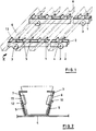
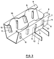
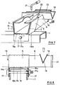
- the support rails 1 are each designed as U-rails open at the bottom and have 2 rollers 3 between their downwardly projecting flanges, with which the support rails 1 can be moved on a flat surface or on rails of a frame.
- Holding tabs 5 are angled upward over the length of the upper web surface 4 of each running rail. In the embodiment shown in FIGS. 1-3, the retaining tabs 5 are punched out of the web surface 4 and angled upwards.
- the cultivation channel 6 has upwardly diverging side walls 7.
- the inclination of the holding tabs 5 is adapted to the inclined course of these side walls 7.
- edge strips 8 are folded inwards from the upper edges of the side walls 7.
- the edge strips 8 have holding recesses 9 which are arranged at a distance from one another in the longitudinal direction of the channel and are adapted to the shape of the plant pots to be accommodated.
- holding strips 10 are punched out of the side walls 7 and folded into the interior of the culture channel 6. These holding strips serve to additionally hold the section of the received plant pot located below the edge strips 8, in order to prevent tipping in the longitudinal direction of the gutter.
- punch openings 11 are created in the channel side walls 7. These punch openings 11 are spaced above the channel bottom, so that the water flowing along the channel bottom cannot escape through the punch opening 11.
- the retaining tabs 5 which are edged up from the mounting rails 1 are essentially rigid and have locking projections 12 or locking projections which project against one another and engage in the punched openings 11 in a snap-in manner.
- the culture channels 6 can be pressed together resiliently for engaging and disengaging. In this way, the culture channels 6 are held on the mounting rails 1.
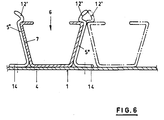
- the retaining tabs 5 'in the embodiment of FIGS. 4 and 5 are each part of a bracket 13 which consists of a base plate 14 and the holding tabs 5 'angled upward on both sides thereof.
- the base plate 14 of each bracket 13 is connected to the overlying web surface 4 of the mounting rail 1, for example by means of spot welding.
- the retaining tabs 5 ' are designed to be resilient in the longitudinal direction of the mounting rails 7.
- the locking projections 12 'at the upper ends of the holding tabs 5' are formed here by a hook-shaped end section of the holding tabs 5 '. As can be seen from FIG. 5, these latching projections 12 ′ also engage in the punched openings 11, which are formed in the side walls 7 of the culture channels 6. The upper, bent-back tongue of the end section of the retaining tab 5 'facilitates the engagement of the culture channels 6.
- the holding tabs 5 '' can also be made so long that they reach over the top edge of the culture channels 6. In this embodiment, it is not necessary for the culture channels 6 to have separate latching recesses.
- the retaining tabs 5 ′′ and / or the upper edges of the culture channels 6 can be designed to be resilient in order to enable them to snap into place.
- Fig. 6 it is further indicated by dash-dotted lines that one or more additional culture channels can be loosely set between the culture channels 6 held by the holding tabs 5 ''.
- the retaining tabs 5 '' in such a way that - as is also indicated by dash-dotted lines - they have locking projections 12 'pointing in both directions, so that the additionally set cultivation channels 6 (shown here with dash-dotted lines) are held in a snap-in manner become.
- the holding tabs 5 ′′ - shown individually here - on the web surface of the mounting rails 1 welded, riveted, screwed or fastened by joining using spot welding.
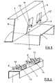
- the retaining elements connecting the cultivation channels 6 to the two mounting rails 1 are in this case designed as one-piece holders 15 which are detachably placed on the mounting rails 1.
- Each holder 15 has a rectangular base plate 16, from the two opposite edges 16a of which one leg 17 projects downward.
- the two legs 17 rest on the outer sides of the mounting rails 1.
- Retaining tabs 5 protrude from the two other edges 16b of the base plate 16 and engage with their ends over the upper edges of the culture channel 6.
- the cultivation channels 6 are designed to be resilient, so that their side walls 7 can be resiliently pressed inwards in order to be engaged or disengaged between the holding tabs 5, which are rigid in this case.
- the entire holder 15 is rigid. Instead, the holder 15 can also be made resilient.
- the two legs 17 of the holder 15 and the mounting rails 1 each have mutually aligned bores through which a common retaining bolt 17a is inserted.
- the retaining bolt 17a is secured by a releasable securing element 17b, for example an inserted wedge or split pin.
- the holding bolt 17a enables the holder 15 to be assembled and disassembled quickly, a positive connection being produced. This positive connection makes it possible to connect several Lift channels 6 together with their two mounting rails 1 as a unit and transport.
- a plurality of cultivation channels 6 are connected near their one end by a common irrigation channel 18 which is placed horizontally and transversely to the culture channels 6, i.e. runs parallel to the mounting rails 1.
- two outlet holes 20 are assigned to each culture channel 6 in a side wall of the irrigation channel 18.
- the irrigation channel 18, which is closed at its ends (not shown), is supplied with water and dissolved fertilizers continuously via a water inlet 21 or only when it passes through an irrigation station. The water runs through the lower outlet hole 20 into the respectively assigned culture channel 6 in the desired amount.
- Each cultivation channel 6 has a slight slope, so that the water supplied runs along the culture channel 6 and is absorbed by the plants set. Excess water runs at the opposite end of the culture channels 6 into a common collecting channel and can be recirculated from there.
- An upper, larger outlet hole 20 serves as an overflow if the smaller outlet hole located below is blocked.
- the cultivation channels 6 each have incisions 19 extending from their upper edge, into which the common irrigation channel 18 is inserted.
- the incisions 19 and Irrigation channel 18 with V-profile executed at the same angle.
- the culture channels 6 (as well as the irrigation channels 18) can each be closed at their ends with a cap 22. With a sufficient slope of the cultivation channels 6, such caps 22 are not required.
Landscapes
- Life Sciences & Earth Sciences (AREA)
- Environmental Sciences (AREA)
- Cultivation Receptacles Or Flower-Pots, Or Pots For Seedlings (AREA)
Claims (19)
- Supports pour plusieurs gouttières de culture (6) pour plantes, les supports étant constitués de profilés porteurs (1) longitudinaux et horizontaux s'étendant transversalement aux gouttières de culture, lesdits profilés présentant des éléments de retenue faisant saillie de leur surface vers le haut, caractérisés en ce que les éléments de retenue se présentent sous la forme d'éclisses de retenue individuelles (5, 5', 5'') faisant respectivement saillie vers le haut de la surface des profilés porteurs et en ce que chaque gouttière de culture (6) est maintenue par encliquetage entre deux éclisses de retenue (5, 5', 5'').
- Supports selon la revendication 1, caractérisés en ce que les éclisses de retenue (5') sont réalisées de manière élastique dans la direction longitudinale des profilés porteurs (1).
- Supports selon la revendication 1, caractérisés en ce que les éclisses de retenue se présentent sous forme sensiblement rigide et les gouttières de culture (6) sont compressibles de manière élastique au moins sur leurs bords supérieurs.
- Supports selon la revendication 1, caractérisés en ce que, respectivement, deux éclisses de retenue (5, 5') en regard l'une de l'autre s'enclenchent par des saillies d'encliquetage (12, 12') saillant de celles-ci dans des évidements d'encliquetage (11) des gouttières de culture (6).
- Supports selon la revendication 1, caractérisés en ce que, respectivement, deux éclisses de retenue (5'') en regard l'une de l'autre s'encliquètent par des saillies d'encliquetage (12') saillant de celles-ci sur les bords supérieurs des gouttières de culture (6).
- Supports selon la revendication 1 ou 5, caractérisés en ce que les profilés porteurs (1) présentent des galets de roulement (3).
- Supports selon la revendication 5, caractérisés en ce que les éclisses de retenue (5) sont matricées dans la surface transversale supérieure (4) des profilés porteurs (1) en forme de U et sont pliées vers le haut.
- Supports selon la revendication 5, caractérisés en ce que les éclisses de retenue (5') sont repliées vers le haut à partir d'un pied (14) qui est relié à la partie supérieure du profilé porteur (1).
- Supports selon la revendication 8, caractérisés en ce que deux éclisses de retenue (5') en regard l'une de l'autre sont réalisées avec un pied commun (14) sous la forme d'un étrier de retenue d'une pièce (13) constitué de tôle.
- Supports selon la revendication 9, caractérisés en ce que l'étrier de retenue (13) est fixé sur la surface transversale (4) du profilé porteur (1) par soudage par points, rivetage ou assemblage.
- Supports selon la revendication 11, caractérisés en ce que les profilés porteurs (1) se présentent respectivement sous la forme de profilés en U ouverts vers le bas.
- Supports selon l'une quelconque des revendications 1 à 11, caractérisés en ce que les éléments de retenue sont formés par des supports (15) qui sont montés sur les profilés porteurs (1) de manière amovible.
- Supports selon la revendication 12, caractérisés en ce que le support (15) présente une embase (16) qui comporte deux branches (17) faisant saillie vers le bas sur deux bords en regard (16a), lesdites branches se trouvant sur les faces externes des profilés porteurs (1), et en ce que les éclisses de retenue (5) font saillie vers le haut, des deux autres côtés (16b) de l'embase (16).
- Supports selon la revendication 13, caractérisés en ce que les branches (17) des supports (15) et les profilés porteurs (1) présentent des orifices respectivement alignés les uns avec les autres et à travers lesquels est enfiché un boulon de retenue commun (17a) qui présente un élément de fixation amovible (17b).
- Supports selon la revendication 13, caractérisés en ce que le support (15) est rigide et en ce que les parois latérales (7) des gouttières de culture (6) sont élastiques.
- Supports selon la revendication 12 ou 13, caractérisés en ce que le support (15) est élastique.
- Supports selon la revendication 1, caractérisés en ce que plusieurs gouttières de culture (6) sont reliées, à proximité de leur première extrémité, par une gouttière d'irrigation (18) commune s'étendant parallèlement aux profilés porteurs (1), sur laquelle au moins un orifice d'évacuation (20) est affecté à chaque gouttière de culture (6).
- Supports selon la revendication 16, caractérisés en ce que les gouttières de culture (6) présentent des découpes (19) pratiquées dans leur bord supérieur, dans lesquelles la gouttière d'irrigation (18) commune est insérée.
- Supports selon la revendication 17, caractérisés en ce que les découpes (19) et la gouttière d'irrigation (18) présentent le même profil.
Applications Claiming Priority (4)
| Application Number | Priority Date | Filing Date | Title |
|---|---|---|---|
| DE4014925 | 1990-05-10 | ||
| DE4014925 | 1990-05-10 | ||
| DE4026105A DE4026105C1 (en) | 1990-05-10 | 1990-08-17 | Carrier for plant culture troughs - has rails with sprung fish plates to retain troughs for plants |
| DE4026105 | 1990-08-17 |
Publications (2)
| Publication Number | Publication Date |
|---|---|
| EP0456077A1 EP0456077A1 (fr) | 1991-11-13 |
| EP0456077B1 true EP0456077B1 (fr) | 1995-11-02 |
Family
ID=25893037
Family Applications (1)
| Application Number | Title | Priority Date | Filing Date |
|---|---|---|---|
| EP91106943A Expired - Lifetime EP0456077B1 (fr) | 1990-05-10 | 1991-04-29 | Support de gouttières de culture |
Country Status (2)
| Country | Link |
|---|---|
| EP (1) | EP0456077B1 (fr) |
| DE (2) | DE4026105C1 (fr) |
Families Citing this family (5)
| Publication number | Priority date | Publication date | Assignee | Title |
|---|---|---|---|---|
| GB2255498A (en) * | 1991-05-08 | 1992-11-11 | Palmyra Limited | Adjustable seed tray frame |
| BE1012650A3 (nl) * | 1997-07-15 | 2001-09-04 | Bekaert Sa Nv | Draadpaneel voor het ondersteunen van bloempotten |
| DE20111912U1 (de) | 2001-07-23 | 2002-01-03 | Jung, Helmut, 76593 Gernsbach | Anzucht- und Transportbehältnis für Kulturpflanzen |
| NL1020882C2 (nl) * | 2002-06-17 | 2003-12-19 | W M Systems B V | Stelsel met over rails verplaatsbare plantdragers. |
| NL2031269B1 (en) * | 2022-03-14 | 2023-09-20 | Pb Techniek B V | Cultivation trough and transport system |
Family Cites Families (4)
| Publication number | Priority date | Publication date | Assignee | Title |
|---|---|---|---|---|
| CH441860A (fr) * | 1966-07-05 | 1967-08-15 | Ferrand Marcel | Dispositif pour la culture sans sol |
| US4163342A (en) * | 1978-03-24 | 1979-08-07 | General Electric Company | Controlled environment agriculture facility and method for its operation |
| US4476651A (en) * | 1983-01-27 | 1984-10-16 | Geoffrey Drury | Apparatus and method for transporting growing plants |
| DE3839664A1 (de) * | 1988-11-24 | 1990-05-31 | Ruediger Fischer | Trog fuer pflanzentoepfe |
-
1990
- 1990-08-17 DE DE4026105A patent/DE4026105C1/de not_active Expired - Lifetime
-
1991
- 1991-04-29 DE DE59106798T patent/DE59106798D1/de not_active Expired - Fee Related
- 1991-04-29 EP EP91106943A patent/EP0456077B1/fr not_active Expired - Lifetime
Also Published As
| Publication number | Publication date |
|---|---|
| DE4026105C1 (en) | 1991-06-20 |
| EP0456077A1 (fr) | 1991-11-13 |
| DE59106798D1 (de) | 1995-12-07 |
Similar Documents
| Publication | Publication Date | Title |
|---|---|---|
| DE3012874C2 (de) | Topfsatz für Pflanzen | |
| DE3880225T2 (de) | Verbundene Behälter. | |
| DE69725421T2 (de) | Gewächshausdach | |
| EP0374898A1 (fr) | Table de plantes | |
| EP0456077B1 (fr) | Support de gouttières de culture | |
| EP1426521A2 (fr) | Façade pour murs | |
| EP0445197B1 (fr) | Bac pour pots de fleurs | |
| EP4168721B1 (fr) | Dispositif de fixation pour fixer des modules solaires | |
| DE2256584B2 (de) | Dacheindeckung | |
| EP0095455B1 (fr) | Piège à neige pour toits | |
| DE19844020C2 (de) | Kulturplatte zum Bewurzeln von Jungpflanzen | |
| EP1764454A2 (fr) | Crochet pour monter des modules d'une installation solaire sour les toits | |
| DE2033550A1 (de) | Profilierter Trager zur Abstutzung und Verspannung von Platten | |
| DE19912143B4 (de) | Bauteilset zum Bau eines Gewächshauses | |
| EP4255168A1 (fr) | Récipient de plantation | |
| DE202020105637U1 (de) | Vorrichtung zur Aufnahme von Pflanztöpfen | |
| DE3439425C2 (de) | Blumenkasten für mit Dacheindeckungsplatten eingedeckte Dächer | |
| DE2651783A1 (de) | Tasche, insbesondere schultasche | |
| DE1530862A1 (de) | Auf dem Dach eines Fahrzeuges anzuordnender Traeger | |
| DE102019132124B4 (de) | Bausatz zur Montage eines bepflanzbaren Wandgartens | |
| DE3713442A1 (de) | Halterung fuer holzlatten an gebaeuden, insbesondere first- oder gratlatten in einer steildachkonstruktion | |
| DE102022113692A1 (de) | Pflanzgefäss | |
| DE7100680U (de) | Tragarm | |
| EP0010658B1 (fr) | Moyen de fixation pour un revêtement de façade | |
| DE1808787A1 (de) | Tragstuetze,insbesondere Radiatorstuetze |
Legal Events
| Date | Code | Title | Description |
|---|---|---|---|
| PUAI | Public reference made under article 153(3) epc to a published international application that has entered the european phase |
Free format text: ORIGINAL CODE: 0009012 |
|
| AK | Designated contracting states |
Kind code of ref document: A1 Designated state(s): BE DE DK FR IT NL |
|
| 17P | Request for examination filed |
Effective date: 19920506 |
|
| 17Q | First examination report despatched |
Effective date: 19950126 |
|
| GRAA | (expected) grant |
Free format text: ORIGINAL CODE: 0009210 |
|
| AK | Designated contracting states |
Kind code of ref document: B1 Designated state(s): BE DE DK FR IT NL |
|
| PG25 | Lapsed in a contracting state [announced via postgrant information from national office to epo] |
Ref country code: NL Free format text: LAPSE BECAUSE OF FAILURE TO SUBMIT A TRANSLATION OF THE DESCRIPTION OR TO PAY THE FEE WITHIN THE PRESCRIBED TIME-LIMIT Effective date: 19951102 Ref country code: BE Effective date: 19951102 Ref country code: DK Effective date: 19951102 Ref country code: FR Effective date: 19951102 Ref country code: IT Free format text: LAPSE BECAUSE OF FAILURE TO SUBMIT A TRANSLATION OF THE DESCRIPTION OR TO PAY THE FEE WITHIN THE PRE;WARNING: LAPSES OF ITALIAN PATENTS WITH EFFECTIVE DATE BEFORE 2007 MAY HAVE OCCURRED AT ANY TIME BEFORE 2007. THE CORRECT EFFECTIVE DATE MAY BE DIFFERENT FROM THE ONE RECORDED.SCRIBED TIME-LIMIT Effective date: 19951102 |
|
| REF | Corresponds to: |
Ref document number: 59106798 Country of ref document: DE Date of ref document: 19951207 |
|
| EN | Fr: translation not filed | ||
| NLV1 | Nl: lapsed or annulled due to failure to fulfill the requirements of art. 29p and 29m of the patents act | ||
| PLBE | No opposition filed within time limit |
Free format text: ORIGINAL CODE: 0009261 |
|
| STAA | Information on the status of an ep patent application or granted ep patent |
Free format text: STATUS: NO OPPOSITION FILED WITHIN TIME LIMIT |
|
| 26N | No opposition filed | ||
| PGFP | Annual fee paid to national office [announced via postgrant information from national office to epo] |
Ref country code: DE Payment date: 20000428 Year of fee payment: 10 |
|
| PG25 | Lapsed in a contracting state [announced via postgrant information from national office to epo] |
Ref country code: DE Free format text: LAPSE BECAUSE OF NON-PAYMENT OF DUE FEES Effective date: 20020301 |