EP0456852A1 - Outil de rivetage avec alimentation de rivets automatique - Google Patents
Outil de rivetage avec alimentation de rivets automatique Download PDFInfo
- Publication number
- EP0456852A1 EP0456852A1 EP90109091A EP90109091A EP0456852A1 EP 0456852 A1 EP0456852 A1 EP 0456852A1 EP 90109091 A EP90109091 A EP 90109091A EP 90109091 A EP90109091 A EP 90109091A EP 0456852 A1 EP0456852 A1 EP 0456852A1
- Authority
- EP
- European Patent Office
- Prior art keywords
- jaws
- rivet
- delivery line
- end piece
- transfer channel
- Prior art date
- Legal status (The legal status is an assumption and is not a legal conclusion. Google has not performed a legal analysis and makes no representation as to the accuracy of the status listed.)
- Granted
Links
- 230000005484 gravity Effects 0.000 claims description 3
- 238000000034 method Methods 0.000 description 5
- 238000010276 construction Methods 0.000 description 2
Images
Classifications
-
- B—PERFORMING OPERATIONS; TRANSPORTING
- B21—MECHANICAL METAL-WORKING WITHOUT ESSENTIALLY REMOVING MATERIAL; PUNCHING METAL
- B21J—FORGING; HAMMERING; PRESSING METAL; RIVETING; FORGE FURNACES
- B21J15/00—Riveting
- B21J15/10—Riveting machines
- B21J15/30—Particular elements, e.g. supports; Suspension equipment specially adapted for portable riveters
- B21J15/32—Devices for inserting or holding rivets in position with or without feeding arrangements
-
- B—PERFORMING OPERATIONS; TRANSPORTING
- B21—MECHANICAL METAL-WORKING WITHOUT ESSENTIALLY REMOVING MATERIAL; PUNCHING METAL
- B21J—FORGING; HAMMERING; PRESSING METAL; RIVETING; FORGE FURNACES
- B21J15/00—Riveting
- B21J15/10—Riveting machines
- B21J15/105—Portable riveters
-
- Y—GENERAL TAGGING OF NEW TECHNOLOGICAL DEVELOPMENTS; GENERAL TAGGING OF CROSS-SECTIONAL TECHNOLOGIES SPANNING OVER SEVERAL SECTIONS OF THE IPC; TECHNICAL SUBJECTS COVERED BY FORMER USPC CROSS-REFERENCE ART COLLECTIONS [XRACs] AND DIGESTS
- Y10—TECHNICAL SUBJECTS COVERED BY FORMER USPC
- Y10T—TECHNICAL SUBJECTS COVERED BY FORMER US CLASSIFICATION
- Y10T29/00—Metal working
- Y10T29/53—Means to assemble or disassemble
- Y10T29/53709—Overedge assembling means
- Y10T29/53717—Annular work
- Y10T29/53726—Annular work with second workpiece inside annular work one workpiece moved to shape the other
- Y10T29/5373—Annular work with second workpiece inside annular work one workpiece moved to shape the other comprising driver for snap-off-mandrel fastener; e.g., Pop [TM] riveter
Definitions
- the invention relates to a rivet setting device with a device for feeding blind rivets or rivet nuts to the rivet head containing the clamping jaws with a delivery line leading to the latter.
- the present invention has for its object an improved automatic riveting tool to make available that is characterized by an inexpensive construction and works reliably in operation.
- the delivery line is provided with a separate delivery line end piece that is pivotable with respect to the rivet setting device, that the delivery line end piece in a transfer channel in a first position in relation to the rivet head advanced in front of this swings in and that in a second retracted position of the transfer channel, the conveyor line end piece is pivoted out of this.
- the transfer channel is advantageously provided with jaws that can be swung out to the side.
- the jaws close the transfer channel to the front and, during the backward movement, place the rivet on the outside of the mouthpiece.
- the transfer channel is formed in the jaws.
- the rivet head and the guide sleeve are connected at their rear end to a suction line.
- the invention proposes that when the transfer channel moves backwards, the rivet head swings the jaws out to the side, in which the mouthpiece emerges between the jaws.
- the end of the conveying line can advantageously be mounted on a swivel piece which can be rotated about an axis, the end of the conveying line pushing downward due to its gravity or by a helical spring.
- the invention proposes that the jaws are combined to form a feed slide, which is displaceable on a guide sleeve carrying the rivet head.
- the jaws are attached to the feed slide by means of leaf springs.
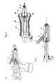
- FIG. 1 shows a rivet setting tool 1, which essentially consists of an upper tool part 2, a handle part 3 with a rivet feed device 4.
- a working piston 4 not shown, which is provided with a working piston rod which, as shown in FIG. 2, runs through a guide sleeve 5 to the rivet head 6 and carries the clamping jaws at the front end.
- a pressure piston is provided in the grip part 3 and the container 8 shown in dashed lines sits at the end of the upper grip part 2 to catch the torn rivet pins. With 9 compressed air or suction lines are marked.
- a pusher 10 is provided for actuating the riveting tool.
- the device has a delivery line 11 for feeding rivets, which at the end has a specially designed delivery line end piece 12. This is attached to a pivot piece 13 that is rotatably mounted at 14.
- the conveyor line end piece is pivoted out of the feed channel 15, which is shown in the retracted position in FIG. 1, wherein, as shown in FIG. 2, the jaws 16 closing at the front in the conveying channel are pivoted out to the side, in which the rivet head 6 with the mouthpiece 7 emerges between the jaws 16.
- the jaws 16 are combined to form a carriage, generally designated 17, which is slidably arranged on the guide sleeve 5.
- the jaws 16 are fastened to the carriage 17 with the aid of leaf springs 18, so that the jaws 16 can be pivoted to the side in a structurally simple manner when the rivet head 6 with the mouthpiece 7 emerges between the jaws.
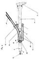
- the carriage 17 and thus the transfer channel 15 are pushed forward on the guide sleeve 5 and the delivery line end piece 12 of the delivery line 11 pivots into the transfer channel 15, as shown in broken lines in FIG. 3 and shown in section in FIG.
- the jaws 16 pivot inwards and close the transfer duct 15 at the front.
- the conveying line end piece 12 swings in directly behind the jaws 16 and a recess 19 is provided in these, which serves as a transfer channel and receives the rivets when they are fed from the conveying line 11 via the conveying line end piece 12.
- the slide 17 is moved into the retracted position on the guide sleeve 5, the rivet head 6 swiveling out the delivery line end piece 12 and the rivet 20 seated in the recess 19 of the jaws 16 into the mouthpiece 7 of the rivet head 6 is inserted, as shown in dashed lines on the left in FIG.
- the device is then ready to carry out the riveting process.
- the torn-off rivet pin is then conveyed into the collecting container 8 through the internal suction channel.
- the carriage 17 is pushed forward again, so that the conveyor line 11 with the conveyor line end piece 12 as shown in FIGS. 3 and 4 shown position can occupy.
- the pivoting of the delivery line end piece 11 can take place due to its gravity. But it is also possible to provide a coil spring 21 which supports the movement process.
Landscapes
- Engineering & Computer Science (AREA)
- Mechanical Engineering (AREA)
- Insertion Pins And Rivets (AREA)
- Automatic Assembly (AREA)
Priority Applications (3)
| Application Number | Priority Date | Filing Date | Title |
|---|---|---|---|
| EP90109091A EP0456852B1 (fr) | 1990-05-15 | 1990-05-15 | Outil de rivetage avec alimentation de rivets automatique |
| DE59006781T DE59006781D1 (de) | 1990-05-15 | 1990-05-15 | Nietsetzgerät mit automatischer Zuführung. |
| US07/612,129 US5042131A (en) | 1990-05-15 | 1990-11-09 | Rivet setting apparatus with automatic rivet feed |
Applications Claiming Priority (1)
| Application Number | Priority Date | Filing Date | Title |
|---|---|---|---|
| EP90109091A EP0456852B1 (fr) | 1990-05-15 | 1990-05-15 | Outil de rivetage avec alimentation de rivets automatique |
Publications (2)
| Publication Number | Publication Date |
|---|---|
| EP0456852A1 true EP0456852A1 (fr) | 1991-11-21 |
| EP0456852B1 EP0456852B1 (fr) | 1994-08-10 |
Family
ID=8203981
Family Applications (1)
| Application Number | Title | Priority Date | Filing Date |
|---|---|---|---|
| EP90109091A Expired - Lifetime EP0456852B1 (fr) | 1990-05-15 | 1990-05-15 | Outil de rivetage avec alimentation de rivets automatique |
Country Status (3)
| Country | Link |
|---|---|
| US (1) | US5042131A (fr) |
| EP (1) | EP0456852B1 (fr) |
| DE (1) | DE59006781D1 (fr) |
Cited By (5)
| Publication number | Priority date | Publication date | Assignee | Title |
|---|---|---|---|---|
| ITBO20130072A1 (it) * | 2013-02-20 | 2014-08-21 | Rivit S R L | Utensile, in particolare pistola, per l'applicazione automatica di elementi di fissaggio |
| CN106734834A (zh) * | 2016-12-13 | 2017-05-31 | 上海围簇自动化技术有限公司 | 一种抽芯铆钉自动定位机构 |
| CN109175197A (zh) * | 2018-08-22 | 2019-01-11 | 沈阳航空航天大学 | 一种凸轮式铆接自动送钉装置 |
| US12194603B2 (en) | 2018-09-05 | 2025-01-14 | Milwaukee Electric Tool Corporation | Blind rivet nut-setting tool |
| US12453999B2 (en) | 2021-07-28 | 2025-10-28 | Milwaukee Electric Tool Corporation | Blind rivet nut-setting tool |
Families Citing this family (8)
| Publication number | Priority date | Publication date | Assignee | Title |
|---|---|---|---|---|
| ES2070707B1 (es) * | 1993-01-19 | 1998-02-16 | Canvibloc Sl | Dispositivo para carga frontal automatica de remaches a una maquina remachadora y metodo para su puesta en practica. |
| US6519997B2 (en) | 2001-01-03 | 2003-02-18 | Allfast Fastening Systems, Inc. | Rivet gun |
| CN100574929C (zh) * | 2004-04-30 | 2009-12-30 | 阿久曼特知识产权有限公司 | 自动进给快速铆接工具 |
| US7040010B2 (en) * | 2004-04-30 | 2006-05-09 | Textron Inc. | Autofeed speed rivet tool |
| US7735218B2 (en) * | 2005-03-11 | 2010-06-15 | Acument Intellectual Properties, Llc | Rivet delivery apparatus and method |
| ITBO20110602A1 (it) * | 2011-10-25 | 2013-04-26 | Rivit S R L | Sistema per l'applicazione automatica di elementi di fissaggio |
| CN110586834B (zh) * | 2019-09-02 | 2024-07-26 | 上海兴韬汽车配件有限公司 | 一种压铆设备 |
| US12485473B2 (en) * | 2024-05-14 | 2025-12-02 | The Boeing Company | Fastener delivery system having an insertion device |
Citations (5)
| Publication number | Priority date | Publication date | Assignee | Title |
|---|---|---|---|---|
| US4604889A (en) * | 1984-12-27 | 1986-08-12 | Huck Manufacturing Company | Automated installation tool for blind fasteners |
| GB2180482A (en) * | 1985-09-19 | 1987-04-01 | Avdel Ltd | Apparatus for installing rivets |
| EP0285739A1 (fr) * | 1987-04-10 | 1988-10-12 | Roald Di Von Maerzthal Roald | Appareil d'alimentation, de renversement et de chargement frontal automatique de rivets, muni d'un pistolet de rivetage |
| US4811881A (en) * | 1987-11-20 | 1989-03-14 | Phillips Plastics Corporation | Apparatus for supplying and installing plastic expansion rivets |
| EP0352623A2 (fr) * | 1988-07-28 | 1990-01-31 | Böllhoff & Co, GmbH & Co KG | Appareil à poser des rivets aveugles |
Family Cites Families (7)
| Publication number | Priority date | Publication date | Assignee | Title |
|---|---|---|---|---|
| DE1172194B (de) * | 1958-12-24 | 1964-06-11 | Reich Maschf Gmbh Karl | Druckluftbetaetigtes Geraet zum Einschlagen von Naegeln |
| DE2441707C3 (de) * | 1974-08-30 | 1981-01-29 | Gesipa Blindniettechnik Gmbh, 6000 Frankfurt | Automatische Nietanlage |
| GB1579902A (en) * | 1978-02-01 | 1980-11-26 | Tucker Fasteners Ltd | Blind riveting |
| DE3506950C2 (de) * | 1985-02-27 | 1995-06-08 | Emhart Inc | Werkzeug zum Setzen von zweiteiligen Befestigern |
| US4630460A (en) * | 1986-02-14 | 1986-12-23 | Usm Corporation | Fastener-setting tool |
| US4747294A (en) * | 1987-03-19 | 1988-05-31 | Usm Corporation | Fastener presentation device |
| US4852376A (en) * | 1987-10-05 | 1989-08-01 | Huck Manufacturing Company | Lockbolt installation tool with cartridge feed |
-
1990
- 1990-05-15 EP EP90109091A patent/EP0456852B1/fr not_active Expired - Lifetime
- 1990-05-15 DE DE59006781T patent/DE59006781D1/de not_active Expired - Fee Related
- 1990-11-09 US US07/612,129 patent/US5042131A/en not_active Expired - Fee Related
Patent Citations (5)
| Publication number | Priority date | Publication date | Assignee | Title |
|---|---|---|---|---|
| US4604889A (en) * | 1984-12-27 | 1986-08-12 | Huck Manufacturing Company | Automated installation tool for blind fasteners |
| GB2180482A (en) * | 1985-09-19 | 1987-04-01 | Avdel Ltd | Apparatus for installing rivets |
| EP0285739A1 (fr) * | 1987-04-10 | 1988-10-12 | Roald Di Von Maerzthal Roald | Appareil d'alimentation, de renversement et de chargement frontal automatique de rivets, muni d'un pistolet de rivetage |
| US4811881A (en) * | 1987-11-20 | 1989-03-14 | Phillips Plastics Corporation | Apparatus for supplying and installing plastic expansion rivets |
| EP0352623A2 (fr) * | 1988-07-28 | 1990-01-31 | Böllhoff & Co, GmbH & Co KG | Appareil à poser des rivets aveugles |
Cited By (5)
| Publication number | Priority date | Publication date | Assignee | Title |
|---|---|---|---|---|
| ITBO20130072A1 (it) * | 2013-02-20 | 2014-08-21 | Rivit S R L | Utensile, in particolare pistola, per l'applicazione automatica di elementi di fissaggio |
| CN106734834A (zh) * | 2016-12-13 | 2017-05-31 | 上海围簇自动化技术有限公司 | 一种抽芯铆钉自动定位机构 |
| CN109175197A (zh) * | 2018-08-22 | 2019-01-11 | 沈阳航空航天大学 | 一种凸轮式铆接自动送钉装置 |
| US12194603B2 (en) | 2018-09-05 | 2025-01-14 | Milwaukee Electric Tool Corporation | Blind rivet nut-setting tool |
| US12453999B2 (en) | 2021-07-28 | 2025-10-28 | Milwaukee Electric Tool Corporation | Blind rivet nut-setting tool |
Also Published As
| Publication number | Publication date |
|---|---|
| DE59006781D1 (de) | 1994-09-15 |
| EP0456852B1 (fr) | 1994-08-10 |
| US5042131A (en) | 1991-08-27 |
Similar Documents
| Publication | Publication Date | Title |
|---|---|---|
| DE2903351C2 (fr) | ||
| DE3876831T2 (de) | Vorrichtung zum zufuehren von nieten. | |
| DE3631657C2 (de) | Vorrichtung zum Setzen von Befestigungselementen mit einer Beschickungseinrichtung | |
| DE3347986C2 (fr) | ||
| DE69507353T2 (de) | Vorrichtung zum automatischen Zuführen für Schraubenstreifen | |
| DE1552324C3 (de) | Werkzeugmaschine mit automatischem Werkzeugwechsel | |
| EP0456852B1 (fr) | Outil de rivetage avec alimentation de rivets automatique | |
| DE1931621A1 (de) | Geraet zum Blindnieten | |
| EP0302128A1 (fr) | Outil de pose de rivets pour poser des rivets borgnes | |
| EP0187995A2 (fr) | Presse à riveter pour fixer un élément de fermeture tel qu'un bouton-pression à un support tel qu'un vêtement | |
| DE1943190C3 (de) | Blindnietvorrichtung zum Setzen von Hohlnieten | |
| DE2754176A1 (de) | Vorrichtung zum beladen von werkzeugmaschinen, insbesondere drehmaschinen | |
| DE2930306C2 (de) | Vereinzelungseinrichtung zur Abgabe einzelner Befestigungselemente | |
| DE3616904C1 (en) | Device for aligning and conveying rivets | |
| DE1069993B (de) | Querfordervorrichtung für eine bolzen-oder mutternpresse | |
| DE4425960C2 (de) | Vorrichtung zum Befestigen eines Griffs an einem Reißverschluß-Schieberkörper | |
| DE2225440C2 (de) | Blindnietvorrichtung zum Setzen von Hohlnieten | |
| DE3049073A1 (de) | "zufuhrvorrichtung" | |
| DE3905808A1 (de) | Verfahren und einrichtung zur automatischen anbringung von klemmen | |
| DE2644716C2 (de) | Vorrichtung zum selbsttätigen Zuführen von stiftförmigen Körpern, insbesondere Stiften für Kesselrohre, zur Hohlelektrode einer elektrischen Schweißvorrichtung | |
| DE1283774B (de) | OEsensetzmaschine | |
| DE1122481B (de) | Zufuehrvorrichtung fuer Drahtenden | |
| EP0018565B1 (fr) | Dispositif pour enrouler des bandes munies de moyens de fixation | |
| DE2225439A1 (de) | Bhndnietvorrichtung zum Setzen von rohrförmigen Blmdnieten | |
| DE3825675A1 (de) | Blindnietgeraet |
Legal Events
| Date | Code | Title | Description |
|---|---|---|---|
| PUAI | Public reference made under article 153(3) epc to a published international application that has entered the european phase |
Free format text: ORIGINAL CODE: 0009012 |
|
| AK | Designated contracting states |
Kind code of ref document: A1 Designated state(s): DE FR GB IT SE |
|
| 17P | Request for examination filed |
Effective date: 19920515 |
|
| 17Q | First examination report despatched |
Effective date: 19930303 |
|
| GRAA | (expected) grant |
Free format text: ORIGINAL CODE: 0009210 |
|
| AK | Designated contracting states |
Kind code of ref document: B1 Designated state(s): DE FR GB IT SE |
|
| PG25 | Lapsed in a contracting state [announced via postgrant information from national office to epo] |
Ref country code: IT Free format text: LAPSE BECAUSE OF FAILURE TO SUBMIT A TRANSLATION OF THE DESCRIPTION OR TO PAY THE FEE WITHIN THE PRE;WARNING: LAPSES OF ITALIAN PATENTS WITH EFFECTIVE DATE BEFORE 2007 MAY HAVE OCCURRED AT ANY TIME BEFORE 2007. THE CORRECT EFFECTIVE DATE MAY BE DIFFERENT FROM THE ONE RECORDED.SCRIBED TIME-LIMIT Effective date: 19940810 Ref country code: FR Effective date: 19940810 Ref country code: GB Effective date: 19940810 |
|
| REF | Corresponds to: |
Ref document number: 59006781 Country of ref document: DE Date of ref document: 19940915 |
|
| RAP2 | Party data changed (patent owner data changed or rights of a patent transferred) |
Owner name: VVG BEFESTIGUNGSTECHNIK BETEILIGUNGS-GMBH |
|
| PG25 | Lapsed in a contracting state [announced via postgrant information from national office to epo] |
Ref country code: SE Effective date: 19941110 |
|
| EN | Fr: translation not filed | ||
| GBV | Gb: ep patent (uk) treated as always having been void in accordance with gb section 77(7)/1977 [no translation filed] |
Effective date: 19940810 |
|
| PLBE | No opposition filed within time limit |
Free format text: ORIGINAL CODE: 0009261 |
|
| STAA | Information on the status of an ep patent application or granted ep patent |
Free format text: STATUS: NO OPPOSITION FILED WITHIN TIME LIMIT |
|
| 26N | No opposition filed | ||
| PGFP | Annual fee paid to national office [announced via postgrant information from national office to epo] |
Ref country code: DE Payment date: 19980610 Year of fee payment: 9 |
|
| PG25 | Lapsed in a contracting state [announced via postgrant information from national office to epo] |
Ref country code: DE Free format text: LAPSE BECAUSE OF NON-PAYMENT OF DUE FEES Effective date: 20000301 |