EP0457486A2 - Appareil de réglage de passage et de température pour les fluides - Google Patents
Appareil de réglage de passage et de température pour les fluides Download PDFInfo
- Publication number
- EP0457486A2 EP0457486A2 EP91304146A EP91304146A EP0457486A2 EP 0457486 A2 EP0457486 A2 EP 0457486A2 EP 91304146 A EP91304146 A EP 91304146A EP 91304146 A EP91304146 A EP 91304146A EP 0457486 A2 EP0457486 A2 EP 0457486A2
- Authority
- EP
- European Patent Office
- Prior art keywords
- temperature
- control
- flow rate
- supply
- flow
- Prior art date
- Legal status (The legal status is an assumption and is not a legal conclusion. Google has not performed a legal analysis and makes no representation as to the accuracy of the status listed.)
- Granted
Links
Images


Classifications
-
- G—PHYSICS
- G05—CONTROLLING; REGULATING
- G05D—SYSTEMS FOR CONTROLLING OR REGULATING NON-ELECTRIC VARIABLES
- G05D23/00—Control of temperature
- G05D23/01—Control of temperature without auxiliary power
- G05D23/13—Control of temperature without auxiliary power by varying the mixing ratio of two fluids having different temperatures
- G05D23/1393—Control of temperature without auxiliary power by varying the mixing ratio of two fluids having different temperatures characterised by the use of electric means
-
- Y—GENERAL TAGGING OF NEW TECHNOLOGICAL DEVELOPMENTS; GENERAL TAGGING OF CROSS-SECTIONAL TECHNOLOGIES SPANNING OVER SEVERAL SECTIONS OF THE IPC; TECHNICAL SUBJECTS COVERED BY FORMER USPC CROSS-REFERENCE ART COLLECTIONS [XRACs] AND DIGESTS
- Y10—TECHNICAL SUBJECTS COVERED BY FORMER USPC
- Y10T—TECHNICAL SUBJECTS COVERED BY FORMER US CLASSIFICATION
- Y10T137/00—Fluid handling
- Y10T137/6198—Non-valving motion of the valve or valve seat
- Y10T137/6253—Rotary motion of a reciprocating valve
- Y10T137/6307—Turbine on valve
-
- Y—GENERAL TAGGING OF NEW TECHNOLOGICAL DEVELOPMENTS; GENERAL TAGGING OF CROSS-SECTIONAL TECHNOLOGIES SPANNING OVER SEVERAL SECTIONS OF THE IPC; TECHNICAL SUBJECTS COVERED BY FORMER USPC CROSS-REFERENCE ART COLLECTIONS [XRACs] AND DIGESTS
- Y10—TECHNICAL SUBJECTS COVERED BY FORMER USPC
- Y10T—TECHNICAL SUBJECTS COVERED BY FORMER US CLASSIFICATION
- Y10T137/00—Fluid handling
- Y10T137/7722—Line condition change responsive valves
- Y10T137/7758—Pilot or servo controlled
- Y10T137/7759—Responsive to change in rate of fluid flow
-
- Y—GENERAL TAGGING OF NEW TECHNOLOGICAL DEVELOPMENTS; GENERAL TAGGING OF CROSS-SECTIONAL TECHNOLOGIES SPANNING OVER SEVERAL SECTIONS OF THE IPC; TECHNICAL SUBJECTS COVERED BY FORMER USPC CROSS-REFERENCE ART COLLECTIONS [XRACs] AND DIGESTS
- Y10—TECHNICAL SUBJECTS COVERED BY FORMER USPC
- Y10T—TECHNICAL SUBJECTS COVERED BY FORMER US CLASSIFICATION
- Y10T137/00—Fluid handling
- Y10T137/8593—Systems
- Y10T137/87571—Multiple inlet with single outlet
- Y10T137/87676—With flow control
- Y10T137/87684—Valve in each inlet
Definitions
- the present invention relates to fluid flow and temperature control apparatus.
- the apparatus is of general application but is best explained in relation to the control of a domestic shower which is supplied with both hot and cold water.
- a prime requirement of such a system is that the output be kept at a required constant temperature regardless of input conditions.
- a number of arrangements have already been proposed to effect such control which utilize a motorized mixing valve under the control of a microprocessor.
- the input parameter for the control system is the temperature of the water output and the control system acts to keep this constant by adjusting the mixing valve to allow, for example, more hot water into the outlet in the case that the outlet temperature falls.
- the overall flow rate in such a system is typically determined empirically by the user.
- temperature sensors are typically slow to react to rapid temperature changes and thus systems utilizing such sensors are prone to supplying water which is not at the required temperature for comparatively long periods of time while re-adjustment is made.
- this is achieved by the use of a flow meter in one or both of the supplies to sense the flow rate and to supply this data as the input parameter to the control system.
- the advantage of this is that flow meters react to changes in condition faster than temperature sensors and this enables the control system of the present invention to react to changes in condition faster than known systems.
- M c , M h , M o designate the mass flow rates in the cold supply, hot supply and outlet respectively
- S designates the specific heat capacity of the liquid being supplied
- T c , T h , T o designate the temperatures of the cold supply, hot supply and outlet respectively.
- equation (1) can be re-arranged to give:
- outlet temperature, T o can be controlled by sensing and controlling only input parameters.
- the mass flow rates, M c and M h are the most likely to be subject to rapid change and these parameters can be sensed by the flow meters which have a fast response time.
- the input temperatures typically vary quite slowly and only a small amount and thus this variation may be sensed accurately using conventional temperature sensors, in spite of their relatively slow response.
- control system may be adapted to take account of the different densities in the hot and cold supplies.
- Figure 1 is a schematic diagram of a first embodiment of this invention. This embodiment is a very simple example of the invention and is useful for understanding the principle of the invention.
- Figure 1 shows a cold water supply 1 and a hot water supply 2 which are mixed in mixing chamber 3, an outlet 4 from which supplies a shower head, not shown.
- the temperatures of the hot and cold water are constant and that the flow rate in the cold water supply 1 is constant. This would be the case when, for instance, the cold water is supplied directly from the domestic mains supply.
- the flow rate in hot water supply 2 is measured by a flow meter 5 and may be controlled by valve 6.
- An electrical output from flow meter 5 indicative of the flow rate is connected to a microprocessor control unit, not shown, which also controls the opening and closing of valve 6.
- the output temperature is set by a user by adjusting the flow rate of the hot water supply 2. This may be done either by direct action on valve 6 or via the control of the microprocessor. Once the temperature has been set, the microprocessor takes over complete control in order to maintain a constant outlet temperature.
- V c , T c and T h are all assumed to be constant. Therefore:
- K1, K2 and K3 are constants.
- V h in order for T o to be held constant it is necessary for V h to be held constant. This is achieved by the microprocessor controlled valve.
- the microprocessor records the value of V h at the initial setting of the required temperature and is operative to maintain V h at this value. If V h falls below this value, for instance caused by a drop in the hot water supply pressure, the microprocessor opens valve 6 to allow V h to rise again to the required valve. Due to the sensitivity and rapid response time of flow meter 5 this correction is effected very rapidly, such that the change in input condition has virtually no effect on the user.
- the microprocessor need have no record of the actual value of the output temperature, T o . It is only necessary that the microprocessor keep a record of the required value of V h .
- the system may be arranged to memorize the required value of V h even when not in use in order that the required outlet temperature may be re-established at a later time without the necessity for setting up the system again.
- Figure 1 has been described with the control in the hot water supply 2. This is for reasons of safety in domestic shower arrangements and the system is adapted such that in the case of failure, valve 6 shuts fully so that no hot water is supplied.
- the invention extends to an arrangement in which the hot water is supplied at a constant flow rate and control of output temperature is effected by a valve in the cold water supply.
- Figure 2 shows a schematic diagram of a second embodiment of the invention.
- the same numerals designate similar parts to those in figure 1.
- Figure 2 shows a cold water supply 1 and a hot water supply 2 which are mixed in mixing chamber 3 and outlet 4 from which supplies a shower, not shown.
- the flow rate in hot water supply 2 is measured by first flow meter 5 and may be controlled by first valve 6.
- the flow rate in cold water supply 3 is measured by second flow meter 7 and may be controlled by second valve 8.
- Electrical outputs from first and second flow meters 5, 7 indicative of the hot and cold flow rates respectively are connected to a microprocessor control unit, not shown, which also controls the opening and closing of first and second valves 6, 8.
- the microprocessor also has an input allowing a user to adjust the required output temperature T o .
- This system may be operated as follows. Initially valves 6,8 are both opened to allow 60% of maximum flow rate in each of cold water supply 1 and hot water supply 2. Second valve 8 is held in this position while the user indicates to the microprocessor whether the output temperature should be increased or decreased. This is adjusted by way of first valve 6 in a similar manner to that described above in relation to figure 1. Once the required output temperature is reached the values of V c and V h are stored by the microprocessor. In this system T c and T h are assumed to be constant and thus output temperature T o may be maintained constant by controlling valves 6, 8 in order to keep V c and V h constant.
- valve 6 is held fixed and valve 8 is used to adjusted the initial output temperature T o , or that both valves 6, 8 are used in the setting of the required output temperature.
- Equation (4) may be re-arranged to give:
- T o will remain constant if the ratio R between the two input flow rates is held constant. For example, if the pressure in the hot supply were to fall suddenly this whould have the effect of (i) causing V h to fall, (ii) causing the value of T o to fall and (iii) causing the value of R to rise.
- R In order to restore T o to its required value, R must be restored to its original value. This may be achieved either by raising V h , reducing V c , or a combination of increasing V h and reducing V c .
- the temperature T o may be restored either by opening first valve 6, partially closing second valve 8, or a combination of these.
- the embodiment of figure 2 may further be operated such that the output flow rate V o may be maintained at a required value.
- a required output flow rate V o may be established by increasing or decreasing the valves of V c and V h while ensuring that the ratio R remains constant.
- total control of the output conditions may be effected in the embodiment of figure 2 by maintaining V c and V h and the values necessary to give the correct ratio for the required value of T o and to give the correct sum for the required value of V o .
- the apparatus shown in figure 2 may also be operated such that the required flow rate V o is established first and then the required temperature T o is established by adjusting V c and V h such that their ratio changes but their sum remains constant.
- apparatus of figure 2 may be arranged such that adjustment of the required flow rate or temperature may be while the shower is in use.
- the system of figure 2 may be also arranged to memorize the required values of, say, R and V o , or V c and V h , in order that the required setting may easily be re-established at a later time.
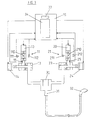
- Figure 3 shows a third preferred embodiment of the present invention which is a control system for supplying water at a user specified temperature and/or flow rate.
- the system of figure 3 monitors both input flow rates via separate flow meters as well as the temperatures of the hot and cold input water.
- the system of figure 3 is largely similar to that of figure 2 and comprises a cold water supply 10 which feeds mixing chamber 30 via flow meter 11 and needle valve 13, and a hot water supply 20 which feeds mixing chamber 30 via flow meter 21 and needle valve 23.
- An outlet 31 from mixing chamber 30 feeds shower head 32.
- Needle valve 13 is operated by stepper motor 14 and needle valve 23 is operated by stepper motor 24.
- control unit 35 which comprises microprocessor 33 and control panel 34.
- Control unit 35 controls the operation of stepper motors 14, 24 and thereby the valves 13, 23.
- Flow meters 11, 21 provide electrical signal to control unit 35 indicative of the instantaneous flow rates of the cold and hot water respectively.
- the flow meters 11, 12 are preferably of the type comprising a turbine 110, 210, a light source (typically an LED) 111, 211 and a photo-sensitive cell 112, 212. These are arranged such that a light beam from the light source 111, 211 shines across the bore of the flow meter to photo-sensitive cell 112,212. This light beam is intermittently cut by turbine 110, 210 as it spins. The faster the flow rate through the flow meter, the faster the turbine spins and the faster the light beam is alternatively cut and restored.
- Control unit 35 is adapted to determine the flow rates V c and V h from the signals output from photo-sensitive cells 112, 212 respectively.
- Control unit 35 thus is able to monitor the flow rates V c and V h and to control valves 13, 23 and is thus able to provide water at the required temperature and/or flow rate as described in relation to figure 2.
- the system of figure 3 further comprises thermistors 15, 25 which provides signals to control unit 35 indicative of the cold and hot supply temperatures T c , T h respectively.
- thermistors 15, 25 which provides signals to control unit 35 indicative of the cold and hot supply temperatures T c , T h respectively.
- T o the absolute value of T o to be determined as all of V c , V h , T c and T h are known. It is therefore possible for the control unit 35 simply to have as inputs the required absolute value of T o and V o and for the valves to be set appropriately to achieve these values, without the need for the empirical setting of the output by the user.
- the measurement of T c and T h also makes it possible to maintain the output temperature even if the input temperatures vary slightly.
- Variations in the input temperature may be expected to be small and gradual and this means they can be ignored as in figure 2 without greatly affecting the accuracy of the system, but this also means that the input temperatures can be accurately monitored by thermistors in spite of their slow response time thus enabling even greater control accuracy and automation to be achieved.
- the control panel 34 can take any suitable form and can provide for presetting the actual desired flow rate and temperature of the shower as mentioned above or can simply provide control switches so that the user can increase or decrease the flow and/or temperature of the output water from the shower head in an empirical manner as described in relation to figure 2.
- the microprocessor 33 is capable of storing preferred settings so that individuals can select their settings from the memory. This is particularly useful with pumped shower systems where the ability to select a remember flow as well as temperature is particularly important for children who are often frightened by the force of pumped hot and cold supplies.
- both hot and cold valves 13 and 23 are opened to their maximum position. This is preferably found by monitoring the flow rate through each valve until a 90° movement of the respective stepper motor 14 or 24 produces no change in the flow meter output. Input temperatures Tc, T h are also monitored until a stable hot and cold supply level is found. The settings of the control valves are altered until the supply having the lower maximum flow rate has a flow rate of 70% of its maximum and the output temperature is equal to 40°C. This is the initialized temperature and flow rate. All alterations by the user are from this initial level.
- any supply alteration of flow rate and temperature is monitored and corrected by adjustment of one or both of the valves 13, 23.
- the first reaction of the system will be to open the valve for which the flow rate is reduced.
- the lower pressure supply control valve at 70% of maximum any reduction in that supply can be compensated for by opening that valve further.
- the required output temperature cannot be maintained by operating the valve then the overall output flow rate will be reduced.
- the priority of the system is to maintain temperature rather than overall flow rate.
- the microprocessor will also correct for variations in input temperature in the same way, however devices for monitoring temperature such as thermistors have a slow response as discussed above. Flow meters can respond to changes in flow instantaneously thus the system will appear to react to flow first and temperature last whereas both will in fact have equal importance.
- the user can alter, via the control panel 34, both the flow rate and the temperature up and down.
- a suitable control panel 34 for use with a system such as that shown in figure 3 is illustrated by way of example in figure 4.
- This comprises a control 40 for switching the system on or off, control 41 for adjusting the output temperature and control 42 for adjusting the output flow rate.
- control 41 for adjusting the output temperature
- control 42 for adjusting the output flow rate.
- the control panel illustrated in figure 4 may be used with a system which is able to memorize preferred settings.
- the above described systems can be used for other arrangements in addition to the domestic shower description given above.
- the system since the system is measuring both flow and temperature, the system could also dispense a pre-determined quantity of water in the form of public shower systems where the showers are only run for a short period.
- the water could be supplied to a bath filler tap enabling the user to simply set the temperature and bath volume level and then leave the apparatus to run the bath.
- control panel of figure 4 permits this by allowing a shower to be selected by control 44 and a bath by control 45.
Landscapes
- Physics & Mathematics (AREA)
- General Physics & Mathematics (AREA)
- Engineering & Computer Science (AREA)
- Automation & Control Theory (AREA)
- Control Of Temperature (AREA)
Applications Claiming Priority (2)
| Application Number | Priority Date | Filing Date | Title |
|---|---|---|---|
| GB9010842 | 1990-05-15 | ||
| GB909010842A GB9010842D0 (en) | 1990-05-15 | 1990-05-15 | Fluid flow and temperature control apparatus |
Publications (3)
| Publication Number | Publication Date |
|---|---|
| EP0457486A2 true EP0457486A2 (fr) | 1991-11-21 |
| EP0457486A3 EP0457486A3 (en) | 1992-11-04 |
| EP0457486B1 EP0457486B1 (fr) | 1996-09-18 |
Family
ID=10676000
Family Applications (1)
| Application Number | Title | Priority Date | Filing Date |
|---|---|---|---|
| EP91304146A Expired - Lifetime EP0457486B1 (fr) | 1990-05-15 | 1991-05-08 | Appareil de réglage de passage et de température pour les fluides |
Country Status (4)
| Country | Link |
|---|---|
| US (1) | US5358177A (fr) |
| EP (1) | EP0457486B1 (fr) |
| DE (1) | DE69122165T2 (fr) |
| GB (1) | GB9010842D0 (fr) |
Cited By (11)
| Publication number | Priority date | Publication date | Assignee | Title |
|---|---|---|---|---|
| GB2261610A (en) * | 1991-11-19 | 1993-05-26 | Computer Shower Co Ltd | Controlling liquid temperature |
| WO1993014451A1 (fr) * | 1992-01-20 | 1993-07-22 | Gregory Allan Stokes | Systeme de commande de douche a minuterie electronique |
| EP0676683A1 (fr) * | 1994-04-09 | 1995-10-11 | Hydrometer GmbH | Commande programmé pour une vanne thermostatique ou une commande de chauffage |
| ES2100117A1 (es) * | 1994-02-23 | 1997-06-01 | Gonzalez Maria Teresa Santiago | Aparato de ducha. |
| WO2002002879A3 (fr) * | 2000-06-29 | 2002-09-06 | Hernandez Joel Valenzuela | Robinet a commande numerique a flux variable |
| WO2007007093A3 (fr) * | 2005-07-12 | 2007-06-14 | Alexander Terrell | Appareil de regulation d'ecoulement de liquide |
| EP2169124A3 (fr) * | 2008-09-24 | 2011-09-28 | VIEGA GmbH & Co. KG | Armature pouvant être commandée électroniquement destinée au mélange d'eau froide et d'eau chaude, notamment pour une table de lavage |
| WO2013020545A1 (fr) * | 2011-08-08 | 2013-02-14 | Schroeck Edgar | Robinet à eau à commande électronique |
| WO2014078883A3 (fr) * | 2012-11-21 | 2014-12-31 | Waizenauer Dietmar | Installation de mélange pour milieux visqueux |
| GB2599958A (en) * | 2020-10-19 | 2022-04-20 | Kohler Mira Ltd | Control system for one or more ablutionary devices |
| EP4036328A4 (fr) * | 2019-09-26 | 2023-11-01 | LIXIL Corporation | Mélangeur d'eau chaude et d'eau froide |
Families Citing this family (67)
| Publication number | Priority date | Publication date | Assignee | Title |
|---|---|---|---|---|
| US5609180A (en) * | 1992-04-27 | 1997-03-11 | Burlington Chemical Co., Inc. | Liquid alkali system for fiber reactive dyeing |
| JP2824443B2 (ja) * | 1994-05-12 | 1998-11-11 | ティ・エフ・シィ株式会社 | 分取用液体クロマトグラフィ装置 |
| CA2162802A1 (fr) * | 1995-11-13 | 1997-05-14 | Peter Zosimadis | Systeme sans fil de surveillance de temperature |
| US6059192A (en) * | 1996-04-04 | 2000-05-09 | Zosimadis; Peter | Wireless temperature monitoring system |
| US5671774A (en) * | 1996-06-18 | 1997-09-30 | Nelson Irrigation Corporation | Rate-of-flow control valve |
| CN1244932A (zh) | 1996-12-12 | 2000-02-16 | 美国标准公司 | 流体流量伺服控制用阀系统 |
| DE29721502U1 (de) * | 1996-12-21 | 1998-04-23 | KSB AG, 67227 Frankenthal | Strangregulierarmatur |
| IT1290356B1 (it) * | 1997-02-18 | 1998-10-22 | Prealpina Tecnoplastica | Valvola per il controllo della temperatura dell'acqua in una macchina lavatrice o lavastoviglie procedimento di trattamento dell'acqua in |
| US6029094A (en) * | 1997-10-14 | 2000-02-22 | Diffut; Eduardo | Shower temperature and flow rate memory controller |
| US6101451A (en) * | 1998-02-23 | 2000-08-08 | Water Management Services, Inc. | Water management system |
| US5979776A (en) * | 1998-05-21 | 1999-11-09 | Williams; Roderick A. | Water flow and temperature controller for a bathtub faucet |
| US6270014B1 (en) | 1999-08-30 | 2001-08-07 | Encon Safety Products | Tempered water blending system |
| US6438770B1 (en) * | 2000-07-25 | 2002-08-27 | Invent Resources, Inc. | Electronically-controlled shower system |
| EP1190656A1 (fr) * | 2000-09-20 | 2002-03-27 | Inter Company Computer, Engineering, Design Services, in het kort : " Concept Design", naamloze vennootschap | Dispositif de distribution de liquide |
| US6430514B1 (en) * | 2000-10-26 | 2002-08-06 | David A. Saar | Water management system |
| WO2003038537A1 (fr) * | 2001-11-01 | 2003-05-08 | The Chicago Faucet Company | Appareil de regulation d'ecoulement et de temperature de liquide |
| US20050004712A1 (en) * | 2003-07-05 | 2005-01-06 | Stevens Jeffrey W. | Method and apparatus for determining time remaining for hot water flow |
| USD528991S1 (en) * | 2003-11-25 | 2006-09-26 | Aisin Seiki Kabushiki Kaisha | Remote control for a toilet seat with bidet |
| USD541225S1 (en) * | 2003-11-25 | 2007-04-24 | Aisin Seiki Kabushiki Kaisha | Remote control for a toilet seat with bidet |
| US7690395B2 (en) | 2004-01-12 | 2010-04-06 | Masco Corporation Of Indiana | Multi-mode hands free automatic faucet |
| US7000850B2 (en) * | 2004-04-27 | 2006-02-21 | Brand New Technology Ltd. | Anti-scald water valve assembly |
| US7458520B2 (en) | 2005-04-19 | 2008-12-02 | Masco Corporation Of Indiana | Electronic proportioning valve |
| US7475827B2 (en) | 2005-04-19 | 2009-01-13 | Masco Corporation Of Indiana | Fluid mixer |
| US7448553B2 (en) | 2005-04-19 | 2008-11-11 | Masco Corporation Of Indiana | Fluid mixer |
| US7584898B2 (en) | 2005-07-01 | 2009-09-08 | Masco Corporation Of Indiana | Manual override for electronic proportioning valve |
| USD569352S1 (en) * | 2005-10-14 | 2008-05-20 | Balboa Instruments, Inc. | Remote control |
| US7867172B1 (en) | 2006-11-09 | 2011-01-11 | Dingane Baruti | Combination toothbrush and peak flow meter system |
| US7624757B2 (en) * | 2006-11-09 | 2009-12-01 | Masco Corporation Of Indiana | Dual function handles for a faucet assembly |
| US8438672B2 (en) | 2005-11-11 | 2013-05-14 | Masco Corporation Of Indiana | Integrated electronic shower system |
| US7328726B2 (en) * | 2006-01-20 | 2008-02-12 | Air Products And Chemicals, Inc. | Ramp rate blender |
| US9243756B2 (en) | 2006-04-20 | 2016-01-26 | Delta Faucet Company | Capacitive user interface for a faucet and method of forming |
| US8162236B2 (en) | 2006-04-20 | 2012-04-24 | Masco Corporation Of Indiana | Electronic user interface for electronic mixing of water for residential faucets |
| US8089473B2 (en) | 2006-04-20 | 2012-01-03 | Masco Corporation Of Indiana | Touch sensor |
| US8118240B2 (en) | 2006-04-20 | 2012-02-21 | Masco Corporation Of Indiana | Pull-out wand |
| US8365767B2 (en) * | 2006-04-20 | 2013-02-05 | Masco Corporation Of Indiana | User interface for a faucet |
| US20070289647A1 (en) * | 2006-06-20 | 2007-12-20 | Elbi International S.P.A. | Mixer valve unit for liquids with associated flow rate meter, particularly for electrical domestic appliances |
| US9243392B2 (en) | 2006-12-19 | 2016-01-26 | Delta Faucet Company | Resistive coupling for an automatic faucet |
| US8944105B2 (en) | 2007-01-31 | 2015-02-03 | Masco Corporation Of Indiana | Capacitive sensing apparatus and method for faucets |
| US7806141B2 (en) | 2007-01-31 | 2010-10-05 | Masco Corporation Of Indiana | Mixing valve including a molded waterway assembly |
| GB2446409B (en) * | 2007-02-06 | 2011-05-04 | Secretary Trade Ind Brit | Fluid mixtures |
| CA2675417C (fr) | 2007-03-28 | 2015-10-13 | Masco Corporation Of Indiana | Capteur tactile capacitif ameliore |
| WO2008130349A1 (fr) | 2007-04-20 | 2008-10-30 | Kohler Co. | Interface utilisateur permettant de commander un appareil sanitaire de salle de bains |
| WO2009075858A1 (fr) | 2007-12-11 | 2009-06-18 | Masco Corporation Of Indiana | Dispositif de couplage capacitif pour robinet |
| KR100974742B1 (ko) * | 2008-06-26 | 2010-08-06 | 현대자동차주식회사 | 수소 공급 시스템의 일체형 압력 조절 액츄에이터 어셈블리 |
| US7841732B2 (en) * | 2008-10-24 | 2010-11-30 | Osram Sylvania Inc. | Shower light |
| US8316883B1 (en) | 2009-03-09 | 2012-11-27 | Craig Watson | Water faucet temperature gauge and display |
| US20110088799A1 (en) * | 2009-10-15 | 2011-04-21 | Woo-Chong Jung | Digital faucet system |
| US8482409B2 (en) * | 2009-11-19 | 2013-07-09 | Masco Corporation Of Indiana | System and method for conveying status information regarding an electronic faucet |
| US8561626B2 (en) | 2010-04-20 | 2013-10-22 | Masco Corporation Of Indiana | Capacitive sensing system and method for operating a faucet |
| US8776817B2 (en) | 2010-04-20 | 2014-07-15 | Masco Corporation Of Indiana | Electronic faucet with a capacitive sensing system and a method therefor |
| CA2800069C (fr) | 2010-05-21 | 2018-07-03 | Masco Corporation Of Indiana | Systeme de douche electronique |
| CA2756952C (fr) | 2010-11-04 | 2020-12-15 | Magarl, Llc | Soupape de commande electrohydraulique thermostatique |
| USD669867S1 (en) * | 2011-04-06 | 2012-10-30 | Moen Incorporated | Control panel |
| USD669866S1 (en) * | 2011-04-06 | 2012-10-30 | Moen Incorporated | Control panel |
| USD669865S1 (en) * | 2011-04-06 | 2012-10-30 | Moen Incorporated | Control panel |
| EP2859153A4 (fr) | 2012-04-20 | 2016-06-22 | Masco Corp | Robinet comportant une baguette d'extraction à détection capacitive |
| US9273450B2 (en) | 2012-06-22 | 2016-03-01 | Kohler Mira Limited | Plumbing fixture with heating elements |
| US9528249B2 (en) * | 2013-02-13 | 2016-12-27 | Component Hardware Group, Inc. | Valve assembly |
| US9182047B2 (en) * | 2013-03-13 | 2015-11-10 | Kohler Mira Limited | Valve with fail-safe device |
| US9057353B2 (en) | 2013-03-15 | 2015-06-16 | Michael S. Aubuchon, Sr. | Shaft-less radial vane turbine generator |
| CN205781212U (zh) | 2015-01-19 | 2016-12-07 | 莫恩股份有限公司 | 电子卫生洁具配件 |
| WO2017075618A1 (fr) * | 2015-10-30 | 2017-05-04 | Lvd Acquisition, Llc | Dispositif de refroidissement de l'eau avec chauffage pour eau chaude rapide |
| GB2568271B (en) | 2017-11-09 | 2020-04-22 | Kohler Mira Ltd | A plumbing component for controlling the mixture of two supplies of water |
| JP7003885B2 (ja) * | 2018-09-18 | 2022-02-04 | 横浜ゴム株式会社 | 航空機用湯水供給システム |
| GB2599956B (en) * | 2020-10-19 | 2024-09-25 | Kohler Mira Ltd | Control system for one or more ablutionary devices |
| CN118765342A (zh) * | 2022-02-28 | 2024-10-11 | As 美国股份有限公司 | 环保淋浴喷头 |
| DE102022129751A1 (de) * | 2022-11-10 | 2024-05-16 | Grohe Ag | Verfahren zum Betreiben einer Sanitärarmatur und Sanitärarmatur |
Family Cites Families (10)
| Publication number | Priority date | Publication date | Assignee | Title |
|---|---|---|---|---|
| US3079950A (en) * | 1954-04-15 | 1963-03-05 | Dole Valve Co | Fluid mixing valve |
| GB1568367A (en) * | 1975-10-14 | 1980-05-29 | Dresser Europe Sa | Liquid blending control system |
| ZA812800B (en) * | 1980-04-29 | 1982-05-26 | Cashmore P | Flow transducer and apparatus utilising the same |
| DE3030716C2 (de) * | 1980-08-14 | 1984-05-30 | Friedrich Grohe Armaturenfabrik Gmbh & Co, 5870 Hemer | Ventileinrichtung |
| KR890001016B1 (ko) * | 1984-12-11 | 1989-04-18 | 마쯔시다덴기산교 가부시기가이샤 | 탕수혼합장치 |
| US4682728A (en) * | 1985-08-27 | 1987-07-28 | Oudenhoven Martin S | Method and apparatus for controlling the temperature and flow rate of a fluid |
| US4696428A (en) * | 1986-07-10 | 1987-09-29 | Paul Shakalis | Electronic fluid temperature flow control system |
| JPH0827017B2 (ja) * | 1987-06-29 | 1996-03-21 | 松下電器産業株式会社 | 給湯装置 |
| US4969598A (en) * | 1987-07-17 | 1990-11-13 | Memry Plumbing Products Corp. | Valve control |
| GB8911059D0 (en) * | 1989-05-15 | 1989-06-28 | Bio Flo Ltd | Laboratory filtration apparatus |
-
1990
- 1990-05-15 GB GB909010842A patent/GB9010842D0/en active Pending
-
1991
- 1991-05-08 EP EP91304146A patent/EP0457486B1/fr not_active Expired - Lifetime
- 1991-05-08 DE DE69122165T patent/DE69122165T2/de not_active Expired - Fee Related
-
1993
- 1993-08-10 US US08/104,409 patent/US5358177A/en not_active Expired - Lifetime
Cited By (14)
| Publication number | Priority date | Publication date | Assignee | Title |
|---|---|---|---|---|
| GB2261610A (en) * | 1991-11-19 | 1993-05-26 | Computer Shower Co Ltd | Controlling liquid temperature |
| WO1993014451A1 (fr) * | 1992-01-20 | 1993-07-22 | Gregory Allan Stokes | Systeme de commande de douche a minuterie electronique |
| ES2100117A1 (es) * | 1994-02-23 | 1997-06-01 | Gonzalez Maria Teresa Santiago | Aparato de ducha. |
| EP0676683A1 (fr) * | 1994-04-09 | 1995-10-11 | Hydrometer GmbH | Commande programmé pour une vanne thermostatique ou une commande de chauffage |
| WO2002002879A3 (fr) * | 2000-06-29 | 2002-09-06 | Hernandez Joel Valenzuela | Robinet a commande numerique a flux variable |
| GB2442676A (en) * | 2005-07-12 | 2008-04-09 | Alexander Terrell | Liquid flow control apparatus |
| WO2007007093A3 (fr) * | 2005-07-12 | 2007-06-14 | Alexander Terrell | Appareil de regulation d'ecoulement de liquide |
| EP2169124A3 (fr) * | 2008-09-24 | 2011-09-28 | VIEGA GmbH & Co. KG | Armature pouvant être commandée électroniquement destinée au mélange d'eau froide et d'eau chaude, notamment pour une table de lavage |
| WO2013020545A1 (fr) * | 2011-08-08 | 2013-02-14 | Schroeck Edgar | Robinet à eau à commande électronique |
| WO2014078883A3 (fr) * | 2012-11-21 | 2014-12-31 | Waizenauer Dietmar | Installation de mélange pour milieux visqueux |
| EP4036328A4 (fr) * | 2019-09-26 | 2023-11-01 | LIXIL Corporation | Mélangeur d'eau chaude et d'eau froide |
| GB2599958A (en) * | 2020-10-19 | 2022-04-20 | Kohler Mira Ltd | Control system for one or more ablutionary devices |
| GB2599958B (en) * | 2020-10-19 | 2024-09-04 | Kohler Mira Ltd | Control system for one or more ablutionary devices |
| US12481298B2 (en) | 2020-10-19 | 2025-11-25 | Kohler Mira Limited | Control system for one or more ablutionary devices |
Also Published As
| Publication number | Publication date |
|---|---|
| DE69122165T2 (de) | 1997-04-10 |
| DE69122165D1 (de) | 1996-10-24 |
| EP0457486B1 (fr) | 1996-09-18 |
| US5358177A (en) | 1994-10-25 |
| EP0457486A3 (en) | 1992-11-04 |
| GB9010842D0 (en) | 1990-07-04 |
Similar Documents
| Publication | Publication Date | Title |
|---|---|---|
| EP0457486B1 (fr) | Appareil de réglage de passage et de température pour les fluides | |
| US4941608A (en) | Hot water supplying system | |
| EP0358173B1 (fr) | Appareil de distribution d'eau chaude | |
| US20040041034A1 (en) | Proportional fluid mixing system | |
| JPS60245947A (ja) | 給湯制御装置 | |
| GB2261610A (en) | Controlling liquid temperature | |
| JPS60134152A (ja) | 給湯装置 | |
| GB2262588A (en) | Fluid temperature controller | |
| KR20060092653A (ko) | 온수기의 온도조절장치 및 온도조절방법 | |
| JP2831504B2 (ja) | シャワー装置 | |
| JPH02174600A (ja) | 発電機用エンジンの回転安定化装置 | |
| JP2513353B2 (ja) | 湯水混合装置 | |
| JPH0277912A (ja) | 自動給湯装置 | |
| JP2505641B2 (ja) | 給湯システム | |
| JPH04320730A (ja) | 給水給湯装置 | |
| JP2523495B2 (ja) | 湯水混合装置 | |
| JPS58217145A (ja) | 流体加熱制御装置 | |
| JPH0239211A (ja) | 給湯制御装置 | |
| JP2661995B2 (ja) | 自動給湯装置 | |
| JP2675846B2 (ja) | 給湯システム | |
| JPH0271026A (ja) | 自動給湯装置 | |
| JP2827352B2 (ja) | 湯水混合制御装置 | |
| JPH0411776B2 (fr) | ||
| JPS6242220B2 (fr) | ||
| JP2762529B2 (ja) | 湯水混合制御装置 |
Legal Events
| Date | Code | Title | Description |
|---|---|---|---|
| PUAI | Public reference made under article 153(3) epc to a published international application that has entered the european phase |
Free format text: ORIGINAL CODE: 0009012 |
|
| AK | Designated contracting states |
Kind code of ref document: A2 Designated state(s): DE ES FR GB IT |
|
| PUAL | Search report despatched |
Free format text: ORIGINAL CODE: 0009013 |
|
| AK | Designated contracting states |
Kind code of ref document: A3 Designated state(s): DE ES FR GB IT |
|
| 17P | Request for examination filed |
Effective date: 19930617 |
|
| 17Q | First examination report despatched |
Effective date: 19941121 |
|
| GRAG | Despatch of communication of intention to grant |
Free format text: ORIGINAL CODE: EPIDOS AGRA |
|
| GRAH | Despatch of communication of intention to grant a patent |
Free format text: ORIGINAL CODE: EPIDOS IGRA |
|
| GRAH | Despatch of communication of intention to grant a patent |
Free format text: ORIGINAL CODE: EPIDOS IGRA |
|
| GRAA | (expected) grant |
Free format text: ORIGINAL CODE: 0009210 |
|
| AK | Designated contracting states |
Kind code of ref document: B1 Designated state(s): DE ES FR GB IT |
|
| PG25 | Lapsed in a contracting state [announced via postgrant information from national office to epo] |
Ref country code: ES Free format text: THE PATENT HAS BEEN ANNULLED BY A DECISION OF A NATIONAL AUTHORITY Effective date: 19960918 Ref country code: FR Effective date: 19960918 |
|
| REF | Corresponds to: |
Ref document number: 69122165 Country of ref document: DE Date of ref document: 19961024 |
|
| ITF | It: translation for a ep patent filed | ||
| EN | Fr: translation not filed | ||
| PLBE | No opposition filed within time limit |
Free format text: ORIGINAL CODE: 0009261 |
|
| STAA | Information on the status of an ep patent application or granted ep patent |
Free format text: STATUS: NO OPPOSITION FILED WITHIN TIME LIMIT |
|
| 26N | No opposition filed | ||
| REG | Reference to a national code |
Ref country code: GB Ref legal event code: 732E |
|
| REG | Reference to a national code |
Ref country code: GB Ref legal event code: IF02 |
|
| PGFP | Annual fee paid to national office [announced via postgrant information from national office to epo] |
Ref country code: DE Payment date: 20080515 Year of fee payment: 18 |
|
| PGFP | Annual fee paid to national office [announced via postgrant information from national office to epo] |
Ref country code: IT Payment date: 20080527 Year of fee payment: 18 |
|
| PGFP | Annual fee paid to national office [announced via postgrant information from national office to epo] |
Ref country code: GB Payment date: 20080514 Year of fee payment: 18 |
|
| GBPC | Gb: european patent ceased through non-payment of renewal fee |
Effective date: 20090508 |
|
| PG25 | Lapsed in a contracting state [announced via postgrant information from national office to epo] |
Ref country code: GB Free format text: LAPSE BECAUSE OF NON-PAYMENT OF DUE FEES Effective date: 20090508 |
|
| PG25 | Lapsed in a contracting state [announced via postgrant information from national office to epo] |
Ref country code: DE Free format text: LAPSE BECAUSE OF NON-PAYMENT OF DUE FEES Effective date: 20091201 |
|
| PG25 | Lapsed in a contracting state [announced via postgrant information from national office to epo] |
Ref country code: IT Free format text: LAPSE BECAUSE OF NON-PAYMENT OF DUE FEES Effective date: 20090508 |