EP0457719A1 - Procédé et dispositif pour l'élimination de liquides de filaments entraînés à grande vitesse - Google Patents
Procédé et dispositif pour l'élimination de liquides de filaments entraînés à grande vitesse Download PDFInfo
- Publication number
- EP0457719A1 EP0457719A1 EP91810292A EP91810292A EP0457719A1 EP 0457719 A1 EP0457719 A1 EP 0457719A1 EP 91810292 A EP91810292 A EP 91810292A EP 91810292 A EP91810292 A EP 91810292A EP 0457719 A1 EP0457719 A1 EP 0457719A1
- Authority
- EP
- European Patent Office
- Prior art keywords
- thread
- deflection
- liquid
- chamber
- filament
- Prior art date
- Legal status (The legal status is an assumption and is not a legal conclusion. Google has not performed a legal analysis and makes no representation as to the accuracy of the status listed.)
- Granted
Links
Images


Classifications
-
- D—TEXTILES; PAPER
- D06—TREATMENT OF TEXTILES OR THE LIKE; LAUNDERING; FLEXIBLE MATERIALS NOT OTHERWISE PROVIDED FOR
- D06B—TREATING TEXTILE MATERIALS USING LIQUIDS, GASES OR VAPOURS
- D06B15/00—Removing liquids, gases or vapours from textile materials in association with treatment of the materials by liquids, gases or vapours
- D06B15/04—Removing liquids, gases or vapours from textile materials in association with treatment of the materials by liquids, gases or vapours by suction
-
- D—TEXTILES; PAPER
- D06—TREATMENT OF TEXTILES OR THE LIKE; LAUNDERING; FLEXIBLE MATERIALS NOT OTHERWISE PROVIDED FOR
- D06B—TREATING TEXTILE MATERIALS USING LIQUIDS, GASES OR VAPOURS
- D06B15/00—Removing liquids, gases or vapours from textile materials in association with treatment of the materials by liquids, gases or vapours
- D06B15/10—Removing liquids, gases or vapours from textile materials in association with treatment of the materials by liquids, gases or vapours by use of centrifugal force
Definitions
- the invention is in the field of textile technology and relates to a method and a device for the gentle removal of excess liquid from high-speed threads according to the preamble of the independent claims.
- Manufacturing processes in particular of synthetic threads consisting of a plurality of fibrils, often comprise one or more process steps which are connected from a treatment of the thread with a liquid.
- Such process steps are, for example, quenching, stretching, dyeing, impregnating or texturing such threads.
- Such liquid treatment processes are preferably carried out in closed chambers which have narrow inlet and outlet openings for the continuous thread or threads.
- the chambers for liquid treatment and in particular their thread outlet openings are designed in such a way that the liquid remains in the chamber and only small amounts can escape through the openings, it cannot be prevented that the thread or threads emerging from the chamber itself carry liquid with them, which then occurs in the case of the thread guiding elements following the liquid treatment chamber with the formation of spray mist is thrown out.
- Such spray mists contaminate neighboring machine parts and represent a loss of treatment liquid, which should advantageously be avoided.
- the threads are still contaminated with too much liquid even after the thread guide elements and may then have to be dried according to the method, using considerable amounts of energy.
- the liquid content in the thread after going through the process should be adjustable.
- the liquid removed from the thread should be collected so that it can be returned to the liquid treatment.
- the process for removing excess liquid from the thread should be able to be operated with a minimum of energy and it should treat the thread so gently that it is also suitable for very sensitive threads and is applicable at every stage of a thread manufacturing process.
- the process should have as little braking effect on the thread so that it can also be used immediately after a stretching chamber.
- the method is said to be particularly applicable for high yarn speeds, ie above 2000 m / min.
- the method according to the invention represents a combination of various sub-methods suitable for the removal of liquid from high-speed threads.
- the thread is deflected, whereby liquid is thrown out of the thread in a known manner by the centrifugal force
- the liquid that is thrown away is directed away from the thread running zone and, thirdly, the entire process takes place in a closed chamber in which a negative pressure is generated by the thread passing through , which contributes to the easier evaporation of the liquid.
- the negative pressure generated by the continuous thread can also be increased by additional means.
- the air that is directly surrounding the thread and entrained by it is peeled off from the thread and replaced. Obviously, in this fourth sub-process, the acceleration of the air in the direction of the thread and the resulting shear forces between the thread and the ambient air act on the thread in a drying manner.
- the process step combined from the four partial processes described is repeated immediately in succession, possibly with slightly varying process parameters, preferably three to four times. This makes it possible to achieve a high drying effect with only very small deflection angles, which is significantly gentler on the thread than a single deflection step by a correspondingly larger deflection angle.
- the process has only a very slight braking effect on the thread, so that it can also be used after a stretching bath without part of the stretching process only taking place during the drying process.
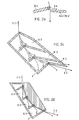
- FIG. 1 shows a method step of the method according to the invention in a very schematic manner.
- a wet thread F.1 is deflected by a deflection element U and liquid is thrown out of it (broken arrow A).
- the ejected liquid is directed away from the thread by a chicane B inclined away from the thread in the direction of gravity.
- the thread runs over the deflection element U, it simultaneously passes through a narrow gap S.
- the air that directly surrounds the thread is peeled off from the thread, which is indicated in the figure by the drawn arrows L.1.
- the thread F will entrain new ambient air (solid arrows L.2), which must be accelerated accordingly.
- the process step takes place in a space surrounding the thread, except for narrow openings for thread inlet and outlet, in which the thread running creates a negative pressure.
- the thread leaves the process step described as drier thread F.2 and is advantageously passed into one or more directly following process steps of the same design in order to be gradually dried to a desired degree of drying.
- the drying effect of a method step according to the invention is greater with a larger deflection angle ⁇ , with a smaller deflection radius r, with a narrower gap S and with lower pressure.
- a method variant to that illustrated by FIG. 1 consists in that the deflection of the thread and its passage through the narrow gap are locally separated from one another.
- FIG. 2a shows how the method according to the invention, which is used to remove liquids from high-speed threads, and which, for example, consists of 4 process steps as described in connection with FIG. 1, runs in a corresponding device which is shown very schematically.
- the wet thread F.1 loaded with liquid is passed through, for example, three chambers K.1-3 and leaves the chamber K.3 as a dry thread F.2, from which most of the liquid has been separated.
- the thread is deflected by a small deflection angle ⁇ , preferably 0.5 to 10 °, for which purpose deflection elements U.1-4 with a radius of curvature r of 0.5 to 5 mm are preferably used .
- the deflection angle is advantageously not chosen to be larger, since a small deflection angle is gentler on the thread and since the repeated deflection can achieve the same liquid-separating effect as with a single deflection by a larger deflection angle.
- the walls 20.1-4 which close off and separate the chambers in the direction of the thread carry the deflection elements U.1-4, form the columns S.1-4 and at the same time function as baffles B.1-4 which act in the form of spray A.1 -3 Direct the flung liquid away from the thread by tilting it in the direction of gravity.
- the walls 20.1-4 are shaped such that their two parts (for example. 20.1 and 20.1 ') have the same height on both sides of the gap in the thread direction. It is also conceivable to shift these heights in the thread direction so that one wall part follows the other in the thread direction.
- FIG. 2a apparently there is no chicane B.4 for the fourth and last process step. If the wall parts 20.4 and 20.4 ', on the other hand, are displaced relative to one another in the thread running direction, as is indicated in FIG. 2b, the wall part 20.4' can still partially take on the function of a chicane B.4.
- the chambers K.1-3 are closed to the outside except for the thread inlet opening, which represents the first gap S.1 traversed by the thread, the thread outlet opening, which represents the last gap S.4, and the suction openings 21 and 21 ', through which the liquid collected in the chambers is aspirated. Since the high-speed thread creates a negative pressure in the chambers, the liquid must be actively sucked out of the device.
- the individual chambers are interconnected through the openings 22.1 and 22.2 (22.1 'and 22.2'). These openings and the suction openings 21.1 and 21.1 'are each arranged at the lowest point in the direction of gravity of the chambers, so that in the Chamber-generated liquid is driven by gravity from one chamber to the next and from the last against the suction.
- a completely soaked thread of 110dtex f34 made of PA66 can be deflected four times by 3, 6, 6 and 3 °, i.e. a total of 18 °, to a moisture level at a throughput speed of 3000 m / min of approximately 11%, so that subsequent rolls, thread guides and the entire exit zone remain practically dry.
- the energy consumption for the process (suction) is low because the flow cross-section over the inlet and outlet opening is very small.
- the design of the schematic device which is illustrated by FIG. 2a, is strongly characterized by the fact that the general thread running direction corresponds to the direction of gravity. This is an advantageous arrangement because it allows the device to be designed in a simple manner. From the principle of the method, however, it is not imperative that the general direction of the thread is chosen in the direction of gravity. Devices for other thread running directions will differ from the device shown schematically primarily by a different design of the walls 20.1-4.
- the variant of the method according to the invention shown in FIG. 2a is suitable for points in the higher-level process at which the thread itself does not have to be deflected. For this reason, the thread is deflected alternately in different directions in such a way that the sum of the deflection angles of the individual process steps is zero, that is, the thread is not deflected over the entire process.
- the method according to the invention for removing unnecessary liquid from a thread begins If a point of the higher-level process is used at which the thread has to be deflected, deflections can always be provided in the same direction for the partial steps of the method according to the invention, such that the sum of the deflection angles in the method steps is equal to the desired deflection angle.
- a corresponding scheme for a method with four substeps is shown in FIG. 2c.
- FIG. 2d An example of a corresponding device variant is shown in Figure 2d. As in FIG. 2c, it is a device with which the method is carried out in the form of four sub-method steps and which is suitable for a deflection point in the higher-level process.
- FIG. 2 Further variants of the method described in connection with FIG. 2 can consist in that there is no deflection of the thread at the entrance to the first chamber in the direction of the thread and at the exit from the last chamber. Furthermore, all chambers can be connected to a central suction device by a separate suction device.
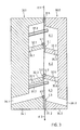
- FIGS. 3 and 4 now show in detail as an example an embodiment of a device with which the described method according to the invention can be carried out. It is a device with which four threads running parallel in the direction of gravity can be freed of liquid.
- the device comprises three chambers K.1-3 and three deflection elements U.1-3. No thread deflection takes place at the entrance to the first chamber K.1 in the thread running direction.
- the device consists of two parts 30.1 and 30.2, of which the block part 30.1 is preferably fastened to a device frame, while the cover part 30.2 can be opened with respect to the block part 30.1 by means of, for example, a closure and hinges, so that the threads can be carried out.
- the functions of the two parts 30.1 and 30.2 with respect to the method according to the invention are the same.
- the plane that separates the two parts 30.1 and 30.2 of the device is the one in which all the threads that run into and out of the device lie.
- FIG. 3 shows this embodiment of the device according to the invention as a section through both device parts 30.1 and 30.2 perpendicular to the plane which separates the two parts and parallel to the thread running direction.
- the threads run into the first chamber K.1 through an inlet slot 31.1 perpendicular to the cutting plane and out of the third chamber K.3 through a corresponding outlet slot 31.2.
- One of the threads is shown in FIG. 3, entering the device as a wetted thread F.1 and exiting the device as a dry thread F.2.
- the three chambers K.1-3 which consist of two identically shaped chamber halves falling away in the direction of gravity from the thread path, one of which lies in the block section 30.1 and one in the cover section 30.2, are closed off from the outside by the outer walls of the two device parts and through the chamber partitions 32.1-4 separated.
- the chamber partitions are displaced relative to one another in such a way that they follow one another in the thread running direction in the following sequence: 32.1, 32.2, 32.4, 32.3, 34.1, 34.2.
- the latter two are not actually chamber partitions, but the thread outer side chamber walls.
- the partitions 32.1-4 are designed in such a way that, when the two device parts 30.1 and 30.2 are adjacent to one another, they leave a gap S.1 and S.2 open for the threads running through, the width of which corresponds to 2 to 10 times the fibril diameter.
- three thread deflection elements U.1-3 are attached to corresponding ledges in such a way that they project a little beyond the plane that separates the two device parts 30.1 and 30.2, and thus the threads from their rectilinear movement in this plane between the entry slot 31.1 and deflect the outlet slot 31.2.
- the deflection elements U.1-3 are preferably ceramic rods with a sliding-friendly surface. In a device such as that shown in FIG.
- the chamber K.1 is connected to the chamber K.2 with, for example, four passages (35.1 and 35.2 in FIG. 3, 35.1 and 35.3 in FIG. 4), which advantageously start from the lowest points in the chamber in the direction of gravity.
- the same passages 35.5-8 connect the chamber K.2 with the chamber K.3.
- the chamber K.3 is connected, for example with two passages 36.1 and 36.2 through the chamber outer wall, which advantageously open into the chamber K.3 at the lowest chamber locations and which have the same angle of inclination as the chamber itself, with a suction device.
- Figure 4 shows a detail of a top view of the inside of the block part 30.1 in the area of the chamber K.1. The course of the thread between the separating bars 37.1-5 and over the deflecting element U.1 can be seen from this.
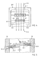
- FIG. 5 shows a detail of another exemplary device variant with adjustable chamber wall parts.
- the chamber wall parts can be moved relative to the plane of separation of the two chamber parts. It is therefore possible to vary not only the deflection angle ⁇ of each partial process step, but also the width of each individual gap S with an arrangement with all chamber wall parts and deflection elements that are of the same design. With such a device, it is possible to set the method in such a way that the thread emerging from the device contains a precisely determined residual moisture.
- An exemplary application for this device is the dosing of spin finish.
- the thread is first impregnated with an excess of spinning finish and then subjected to the process according to the invention with process parameters set in such a way (deflection angle ⁇ , gap width S, negative pressure) that it contains the desired amount of spinning finish when it leaves the device according to the invention.
- FIG. 5 shows an exemplary embodiment variant for the adjustable chamber wall parts.
- Both chamber wall parts 51.1 and 51.2 are not firmly connected to the chamber outer walls 50 of the device, but are guided in them and adjustable with the aid of, for example, adjusting screws 52.1 and 52.2.
- a spring 53 is attached between the chamber wall part and the chamber outer wall, which presses the chamber wall part in its possible position that is furthest away from the chamber outer wall.
- An adjustment of the chamber wall part 51.1 which carries the deflection element U, primarily causes an adjustment of the deflection angle ⁇ .
- An adjustment of the chamber wall part 51.2 relative to the position of the chamber wall part 51.1 given by the deflection angle causes an adjustment of the width of the gap S, which is adjustable, for example, between 0.05 and 0.1 mm.
- FIG. 6 shows a further exemplary embodiment variant for the device for removing liquid from high-speed threads. It corresponds to the devices of Figures 2 and 3 in terms of their function and also in terms of their basic structure. It differs from the previously described design variants by the design of the chamber dividing walls 60.1 / 2/3/4, which are designed in such a way that the chambers enclosing the thread are smaller and, above all, the angle ⁇ between gravity and the part of the liquid leading away Chamber walls 61.1 / 2/3/4 (discharge elements) is smaller.
- the angle ⁇ is advantageously chosen between 10 ° and 60 °.
- the width of the channel 62.1 and 62.2 leading away from the chambers such that the free fall height for the drops is small. It has been shown that the width of the channel at its entrance into the chamber is advantageously chosen between 0.5 and 5 mm.
- the chamber walls according to FIG. 6 can be equipped with separate deflection elements, or else they can be formed from a suitable material such as sintered oxides, for example aluminum oxide, in such a way that they can be used in one piece as a chamber partition, discharge element and deflection element. They can be adjustable transversely to the thread running direction in the manner shown in FIG. So that the effect of the device can be adjusted for a specific application.
- a suitable material such as sintered oxides, for example aluminum oxide
- the local flow formed by the separation of air in the chambers forms a vortex which impacts finer liquid particles (droplets) on the chamber walls and can be separated out, so that the portion of the current flowing back onto the thread contains less liquid than the part leading away from the thread. This creates a dynamic balance that is aligned with the process.
- the contact surfaces of the two main parts can be designed such that they are not flat in the open state (without any force acting on them) and only deform in the closed state (under the action of the forces of the closing means) in such a way that they form a metallic sealing connection.
- Corresponding sealing surfaces can be found in CH registration no. 4496/89 by the same registrant.
Landscapes
- Engineering & Computer Science (AREA)
- Textile Engineering (AREA)
- Treatment Of Fiber Materials (AREA)
- Drying Of Solid Materials (AREA)
- Yarns And Mechanical Finishing Of Yarns Or Ropes (AREA)
Applications Claiming Priority (2)
| Application Number | Priority Date | Filing Date | Title |
|---|---|---|---|
| CH168990 | 1990-05-18 | ||
| CH1689/90 | 1990-05-18 |
Publications (2)
| Publication Number | Publication Date |
|---|---|
| EP0457719A1 true EP0457719A1 (fr) | 1991-11-21 |
| EP0457719B1 EP0457719B1 (fr) | 1996-06-19 |
Family
ID=4216307
Family Applications (1)
| Application Number | Title | Priority Date | Filing Date |
|---|---|---|---|
| EP91810292A Expired - Lifetime EP0457719B1 (fr) | 1990-05-18 | 1991-04-18 | Procédé et dispositif pour l'élimination de liquides de filaments entraînés à grande vitesse |
Country Status (4)
| Country | Link |
|---|---|
| US (1) | US5378377A (fr) |
| EP (1) | EP0457719B1 (fr) |
| JP (1) | JPH04228644A (fr) |
| DE (1) | DE59107941D1 (fr) |
Families Citing this family (2)
| Publication number | Priority date | Publication date | Assignee | Title |
|---|---|---|---|---|
| US6427360B1 (en) * | 2001-01-25 | 2002-08-06 | Lear Corporation | Method for convectively heating permeable material |
| EP1528134B1 (fr) * | 2003-10-17 | 2011-11-09 | Oerlikon Textile GmbH & Co. KG | Dispositif pour le traitement d'un fil en mouvement avec une vapeur |
Citations (3)
| Publication number | Priority date | Publication date | Assignee | Title |
|---|---|---|---|---|
| US3045315A (en) * | 1960-11-02 | 1962-07-24 | Du Pont | Apparatus for orienting continuous filament yarns |
| DE2158932A1 (de) * | 1971-11-27 | 1973-05-30 | Hirschburger Kg Eugen | Verfahren und vorrichtung zur maschinellen kontinuierlichen behandlung von garnen mit fluessigen behandlungsmitteln |
| AU518025B2 (en) * | 1977-11-25 | 1981-09-10 | Commonwealth Scientific And Industrial Research Organisation | Liquid applicator |
Family Cites Families (18)
| Publication number | Priority date | Publication date | Assignee | Title |
|---|---|---|---|---|
| US79412A (en) * | 1868-06-30 | Improvement in maohine fob dbiino tdbdlab fabbios | ||
| US1083005A (en) * | 1913-12-30 | Charles J Burdick | Drip rail-plate for twisting-frames. | |
| US1770310A (en) * | 1926-12-21 | 1930-07-08 | Karplus Hans | Manufacture of hollow artificial threads |
| US1990617A (en) * | 1930-11-01 | 1935-02-12 | Atlas Powder Co | Apparatus for simultaneously spinning, twisting, and purifying rayon |
| GB507782A (en) * | 1938-01-29 | 1939-06-21 | Lustrafil Ltd | Improvements in or relating to the guidng of flaments, thread or yarns during the treatment thereof |
| US2340577A (en) * | 1942-07-11 | 1944-02-01 | Du Pont | Yarn treatment |
| US2579999A (en) * | 1946-11-23 | 1951-12-25 | Rca Corp | Phonograph turntable spindle |
| FR1069785A (fr) * | 1952-06-26 | 1954-07-13 | Fr Des Produits Gelsol Soc | Nouveau procédé et dispositif de décantation |
| US3002804A (en) * | 1958-11-28 | 1961-10-03 | Du Pont | Process of melt spinning and stretching filaments by passing them through liquid drag bath |
| CH510771A (de) * | 1969-07-30 | 1971-02-26 | Luwa Ag | Verfahren zur Behandlung eines endlosen Faserstranges |
| DE2627268A1 (de) * | 1976-06-18 | 1977-12-22 | Hamel Gmbh Zwirnmaschinen | Doppeldraht-zwirnspindel zum nasszwirnen |
| GB1566955A (en) * | 1977-01-27 | 1980-05-08 | Heathcoat & Co Ltd | Heating and drawing of synthetic filaments |
| CH615354A5 (fr) * | 1977-02-04 | 1980-01-31 | Rieter Ag Maschf | |
| EP0273292B1 (fr) * | 1983-12-15 | 1990-12-05 | Toray Industries, Inc. | Dispositif d'enfilage de fil |
| DD233870A1 (de) * | 1985-01-07 | 1986-03-12 | Textima Veb K | Verfahren und vorrichtung zum entfernen von fluessigkeiten aus laufenden endlosen faeden |
| CH672800A5 (fr) * | 1986-03-19 | 1989-12-29 | Schlafhorst & Co W | |
| FR2599390B1 (fr) * | 1986-05-30 | 1988-09-09 | Robatel Slpi | Dispositif pour le chargement et le dechargement des paniers tournants pour l'essorage centrifuge des bobines de fil |
| DE59002052D1 (de) * | 1989-02-24 | 1993-09-02 | Rieter Ag Maschf | Streckkammer. |
-
1991
- 1991-04-18 DE DE59107941T patent/DE59107941D1/de not_active Expired - Fee Related
- 1991-04-18 EP EP91810292A patent/EP0457719B1/fr not_active Expired - Lifetime
- 1991-05-17 JP JP3112933A patent/JPH04228644A/ja active Pending
-
1993
- 1993-07-23 US US08/097,309 patent/US5378377A/en not_active Expired - Fee Related
Patent Citations (3)
| Publication number | Priority date | Publication date | Assignee | Title |
|---|---|---|---|---|
| US3045315A (en) * | 1960-11-02 | 1962-07-24 | Du Pont | Apparatus for orienting continuous filament yarns |
| DE2158932A1 (de) * | 1971-11-27 | 1973-05-30 | Hirschburger Kg Eugen | Verfahren und vorrichtung zur maschinellen kontinuierlichen behandlung von garnen mit fluessigen behandlungsmitteln |
| AU518025B2 (en) * | 1977-11-25 | 1981-09-10 | Commonwealth Scientific And Industrial Research Organisation | Liquid applicator |
Also Published As
| Publication number | Publication date |
|---|---|
| JPH04228644A (ja) | 1992-08-18 |
| US5378377A (en) | 1995-01-03 |
| EP0457719B1 (fr) | 1996-06-19 |
| DE59107941D1 (de) | 1996-07-25 |
Similar Documents
| Publication | Publication Date | Title |
|---|---|---|
| DE69219707T2 (de) | Unterdruckdüsenanordnung zur Behandlung von Bahnen | |
| CH663042A5 (de) | Luftleitkasten an der trockenpartie einer papiermaschine. | |
| DE2544590A1 (de) | Duesentrockner mit ober- und unterhalb einer durchlaufenden warenbahn angeordneten duesenkoerpern | |
| EP0787854A1 (fr) | Dispositif pour guider une bande fibreuse dans une section de séchage à toile unique | |
| EP2179084B1 (fr) | Dispositif de traitement d'un fil multibrin | |
| DE69016536T2 (de) | Vorrichtung in der Trockenpartie einer Papiermaschine. | |
| DD232320A5 (de) | Verfahren und anlage zum trocknen einer mit haertbarem kunstharz impraegnierten warenbahn | |
| DE4013485C2 (de) | Verfahren und Vorrichtung zur Effektivierung der Bahnendaufführung in einer Papiermaschinentrockenpartie | |
| EP0457719B1 (fr) | Procédé et dispositif pour l'élimination de liquides de filaments entraînés à grande vitesse | |
| DE4035985B4 (de) | Absaugverfahren und Absaugvorrichtung in einer Papiermaschine | |
| WO2016000841A1 (fr) | Procédé et dispositif de traction et d'étirement d'une pluralité de fils venant d'être filés | |
| DE4227008A1 (de) | Expandieren und trocknen von tabak | |
| EP0979985B1 (fr) | Dispositif pour le traitement thermique d'une bande de matière textile | |
| DE3536270A1 (de) | Verfahren und vorrichtung zum entfernen von fluessigkeit aus einem laufenden faden | |
| EP0620872B1 (fr) | Procede et dispositif a texturer des fils thermoplastiques | |
| EP0853156A2 (fr) | Dispositif d'aspiration et dispositif de traitement des étoffes textiles | |
| EP1314815A1 (fr) | Appareil pour nettoyer une bande de tamisage dans une machine à papier | |
| EP0468918B1 (fr) | Système de tirage à l'eau avec un effet de freinage variable | |
| EP1449958B1 (fr) | Dispositif pour traiter en particulier pour traiter par dépression, la toile de fabrication ou le feutre d'une machine à papier | |
| EP0828027A2 (fr) | Section de presse et procédé pour la déshydratation d'une bande fibreuse humide | |
| EP1303656A1 (fr) | Procede et dispositif pour traiter en continu des fils synthetiques dans une chambre d'echangeur de chaleur | |
| EP0534895B1 (fr) | Chambre d'étirage | |
| DE3324394C2 (de) | Vorrichtung zum Abscheiden von Verunreinigungen an Offenendspinneinheiten | |
| EP0374541A2 (fr) | Procédé de nettoyage d'un ruban de cardage | |
| DE2359176A1 (de) | Faserbandverdichter fuer aufloesevorrichtungen von offen-end-spinneinheiten |
Legal Events
| Date | Code | Title | Description |
|---|---|---|---|
| PUAI | Public reference made under article 153(3) epc to a published international application that has entered the european phase |
Free format text: ORIGINAL CODE: 0009012 |
|
| AK | Designated contracting states |
Kind code of ref document: A1 Designated state(s): CH DE FR GB IT LI |
|
| 17P | Request for examination filed |
Effective date: 19920402 |
|
| 17Q | First examination report despatched |
Effective date: 19940812 |
|
| GRAH | Despatch of communication of intention to grant a patent |
Free format text: ORIGINAL CODE: EPIDOS IGRA |
|
| GRAA | (expected) grant |
Free format text: ORIGINAL CODE: 0009210 |
|
| AK | Designated contracting states |
Kind code of ref document: B1 Designated state(s): CH DE FR GB IT LI |
|
| PG25 | Lapsed in a contracting state [announced via postgrant information from national office to epo] |
Ref country code: GB Effective date: 19960619 Ref country code: FR Effective date: 19960619 |
|
| REF | Corresponds to: |
Ref document number: 59107941 Country of ref document: DE Date of ref document: 19960725 |
|
| GRAH | Despatch of communication of intention to grant a patent |
Free format text: ORIGINAL CODE: EPIDOS IGRA |
|
| ITF | It: translation for a ep patent filed | ||
| EN | Fr: translation not filed | ||
| GBV | Gb: ep patent (uk) treated as always having been void in accordance with gb section 77(7)/1977 [no translation filed] |
Effective date: 19960619 |
|
| PLBE | No opposition filed within time limit |
Free format text: ORIGINAL CODE: 0009261 |
|
| 26N | No opposition filed | ||
| PGFP | Annual fee paid to national office [announced via postgrant information from national office to epo] |
Ref country code: DE Payment date: 19990326 Year of fee payment: 9 Ref country code: CH Payment date: 19990326 Year of fee payment: 9 |
|
| PG25 | Lapsed in a contracting state [announced via postgrant information from national office to epo] |
Ref country code: LI Free format text: LAPSE BECAUSE OF NON-PAYMENT OF DUE FEES Effective date: 20000430 Ref country code: CH Free format text: LAPSE BECAUSE OF NON-PAYMENT OF DUE FEES Effective date: 20000430 |
|
| REG | Reference to a national code |
Ref country code: CH Ref legal event code: PL |
|
| PG25 | Lapsed in a contracting state [announced via postgrant information from national office to epo] |
Ref country code: DE Free format text: LAPSE BECAUSE OF NON-PAYMENT OF DUE FEES Effective date: 20010201 |
|
| PG25 | Lapsed in a contracting state [announced via postgrant information from national office to epo] |
Ref country code: IT Free format text: LAPSE BECAUSE OF NON-PAYMENT OF DUE FEES;WARNING: LAPSES OF ITALIAN PATENTS WITH EFFECTIVE DATE BEFORE 2007 MAY HAVE OCCURRED AT ANY TIME BEFORE 2007. THE CORRECT EFFECTIVE DATE MAY BE DIFFERENT FROM THE ONE RECORDED. Effective date: 20050418 |