EP0457907A1 - Bolzenvorrichtung zum verbinden von baumaschinengliedern - Google Patents
Bolzenvorrichtung zum verbinden von baumaschinengliedern Download PDFInfo
- Publication number
- EP0457907A1 EP0457907A1 EP90902674A EP90902674A EP0457907A1 EP 0457907 A1 EP0457907 A1 EP 0457907A1 EP 90902674 A EP90902674 A EP 90902674A EP 90902674 A EP90902674 A EP 90902674A EP 0457907 A1 EP0457907 A1 EP 0457907A1
- Authority
- EP
- European Patent Office
- Prior art keywords
- pin
- pin boss
- rigid
- machine operating
- thrust
- Prior art date
- Legal status (The legal status is an assumption and is not a legal conclusion. Google has not performed a legal analysis and makes no representation as to the accuracy of the status listed.)
- Ceased
Links
- 230000002093 peripheral effect Effects 0.000 claims description 8
- 230000009471 action Effects 0.000 description 4
- 230000000694 effects Effects 0.000 description 3
- 238000003780 insertion Methods 0.000 description 3
- 230000037431 insertion Effects 0.000 description 3
- 230000004048 modification Effects 0.000 description 3
- 238000012986 modification Methods 0.000 description 3
- 238000010586 diagram Methods 0.000 description 2
- 238000003754 machining Methods 0.000 description 2
- 230000013011 mating Effects 0.000 description 2
- QNRATNLHPGXHMA-XZHTYLCXSA-N (r)-(6-ethoxyquinolin-4-yl)-[(2s,4s,5r)-5-ethyl-1-azabicyclo[2.2.2]octan-2-yl]methanol;hydrochloride Chemical compound Cl.C([C@H]([C@H](C1)CC)C2)CN1[C@@H]2[C@H](O)C1=CC=NC2=CC=C(OCC)C=C21 QNRATNLHPGXHMA-XZHTYLCXSA-N 0.000 description 1
- 230000006835 compression Effects 0.000 description 1
- 238000007906 compression Methods 0.000 description 1
- 230000008878 coupling Effects 0.000 description 1
- 238000010168 coupling process Methods 0.000 description 1
- 238000005859 coupling reaction Methods 0.000 description 1
- 239000000428 dust Substances 0.000 description 1
- 238000000605 extraction Methods 0.000 description 1
- 230000002452 interceptive effect Effects 0.000 description 1
- 239000010687 lubricating oil Substances 0.000 description 1
- 230000014759 maintenance of location Effects 0.000 description 1
- 238000004519 manufacturing process Methods 0.000 description 1
- 239000007769 metal material Substances 0.000 description 1
- 230000002265 prevention Effects 0.000 description 1
- 230000009467 reduction Effects 0.000 description 1
- 230000000452 restraining effect Effects 0.000 description 1
Images


Classifications
-
- E—FIXED CONSTRUCTIONS
- E02—HYDRAULIC ENGINEERING; FOUNDATIONS; SOIL SHIFTING
- E02F—DREDGING; SOIL-SHIFTING
- E02F9/00—Component parts of dredgers or soil-shifting machines, not restricted to one of the kinds covered by groups E02F3/00 - E02F7/00
- E02F9/006—Pivot joint assemblies
-
- F—MECHANICAL ENGINEERING; LIGHTING; HEATING; WEAPONS; BLASTING
- F16—ENGINEERING ELEMENTS AND UNITS; GENERAL MEASURES FOR PRODUCING AND MAINTAINING EFFECTIVE FUNCTIONING OF MACHINES OR INSTALLATIONS; THERMAL INSULATION IN GENERAL
- F16C—SHAFTS; FLEXIBLE SHAFTS; ELEMENTS OR CRANKSHAFT MECHANISMS; ROTARY BODIES OTHER THAN GEARING ELEMENTS; BEARINGS
- F16C11/00—Pivots; Pivotal connections
- F16C11/04—Pivotal connections
- F16C11/045—Pivotal connections with at least a pair of arms pivoting relatively to at least one other arm, all arms being mounted on one pin
-
- F—MECHANICAL ENGINEERING; LIGHTING; HEATING; WEAPONS; BLASTING
- F16—ENGINEERING ELEMENTS AND UNITS; GENERAL MEASURES FOR PRODUCING AND MAINTAINING EFFECTIVE FUNCTIONING OF MACHINES OR INSTALLATIONS; THERMAL INSULATION IN GENERAL
- F16C—SHAFTS; FLEXIBLE SHAFTS; ELEMENTS OR CRANKSHAFT MECHANISMS; ROTARY BODIES OTHER THAN GEARING ELEMENTS; BEARINGS
- F16C2350/00—Machines or articles related to building
- F16C2350/26—Excavators
-
- Y—GENERAL TAGGING OF NEW TECHNOLOGICAL DEVELOPMENTS; GENERAL TAGGING OF CROSS-SECTIONAL TECHNOLOGIES SPANNING OVER SEVERAL SECTIONS OF THE IPC; TECHNICAL SUBJECTS COVERED BY FORMER USPC CROSS-REFERENCE ART COLLECTIONS [XRACs] AND DIGESTS
- Y10—TECHNICAL SUBJECTS COVERED BY FORMER USPC
- Y10T—TECHNICAL SUBJECTS COVERED BY FORMER US CLASSIFICATION
- Y10T403/00—Joints and connections
- Y10T403/32—Articulated members
- Y10T403/32606—Pivoted
- Y10T403/32819—Pivoted including tension or take-up means
- Y10T403/32827—Interposed spring means coaxial with pivot
-
- Y—GENERAL TAGGING OF NEW TECHNOLOGICAL DEVELOPMENTS; GENERAL TAGGING OF CROSS-SECTIONAL TECHNOLOGIES SPANNING OVER SEVERAL SECTIONS OF THE IPC; TECHNICAL SUBJECTS COVERED BY FORMER USPC CROSS-REFERENCE ART COLLECTIONS [XRACs] AND DIGESTS
- Y10—TECHNICAL SUBJECTS COVERED BY FORMER USPC
- Y10T—TECHNICAL SUBJECTS COVERED BY FORMER US CLASSIFICATION
- Y10T403/00—Joints and connections
- Y10T403/32—Articulated members
- Y10T403/32606—Pivoted
- Y10T403/32819—Pivoted including tension or take-up means
- Y10T403/32836—Acting through tapered surface on bearing component
Definitions
- the present invention relates to a connecting pin device for working machine operating links and, in particular, to a connecting pin device for working machine operating links which is suitable for use as a connecting pin device for the machine operating links of the working unit of a hydraulic excavator or the like.
- Fig. 6 shows an ordinary structure for a connecting pin device for machine operating links adapted to control the posture of a working unit.
- the structure of the connecting pin device for machine operating links shown in the drawing will be described below.
- Links 9R and 9L on one side are spaced away from and opposed to each other.
- pin boss portions 2R and 2L are provided coaxially in end portions of these links 9R and 9L, into which a pin 1 is to be fitted.
- a cylindrical pin boss portion 2M Disposed between these pin boss portions 2R and 2L is a cylindrical pin boss portion 2M, which is provided at one end of a link 9 on the other side, and the pin 1 is inserted into these pin boss portions 2R, 2M and 2L after mating their pin holes with each other, thus effecting pin joint connection of the links 9R, 9L and 9.
- the present invention has been made in view of the above problems in the prior art. It is an object of the present invention to provide a connecting pin device for working machine operating links which is capable of minimizing the axial and radial clearance or play and suppressing an inertial movement in the rotating direction in the pin joint connection portions of machine operating links. In view of this, the present invention provides a structure as shown in Fig.
- the thrust distributing and forming portions 30 cause the rigid-elastic annular members 40 to expand and impart a resilient force F to these rigid-elastic annular members 40, which are held by the thrust distributing and forming portions 30 that are adapted to distribute a thrust in the axial direction S and the radial direction R of the opposed end surfaces 30A and 30B of the pin boss portions 20R, 20L and 23.
- the reactive force energy of the rigid-elastic annular members 40 generates thrusts in the radial direction R and the axial direction S between the respective opposed end surfaces 30A and 30B of the pin boss portions, thereby restraining the play caused by the clearance due to the fitting relationship between the pin 10 and the pin boss portions 20R, 23 and 20L by a strong resilient reactive force -F and quickly suppressing the inertial force when the machine movement stops.
- this resilient reactive force -F also imparts a rotation resistance force to the pin boss portions, thereby contributing to a reduction in the rotary inertial force when the working unit stops its raise movement.
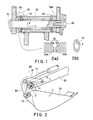
- FIGs. 1 through 5 are diagrams showing embodiments of the connecting pin device for working machine operating links of the present invention, of which:
- FIGs. 2 and 3 are shown as applied to the working unit of a hydraulic excavator.
- a working unit lifting arm 60 Shown in Fig. 2 are a working unit lifting arm 60, a working unit (a bucket) 70, and a machine operating link device 80 including a double-acting hydraulic cylinder 71.
- the machine operating link device 80 consists of tilt levers 81 one end of each of which is rotatably supported by the lifting arm 60, and a tilt rod 82, one end of which is linked with these tilt levers 81 and the other end of which is connected with the linking brackets 72 of the working unit 70.
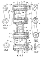
- the working unit 70 is rotatably connected with the front end D of the working unit lifting arm 60 and can be lifted by means of the above machine operating link device 80. More specifically, the linkage of this machine operating link device 80 is effected by the connecting pin device structure shown in Fig. 3, which is a sectional view taken along the line X1-X1 of Fig. 2.
- the upper section of the drawing shows two connecting pin device structures, each of which includes a pair coaxial pin boss portions 21R and 21L, which are spaced away from each other by a fixed interval, and a pin boss portion 23 disposed between these pin boss portions 21R and 21L.
- each of the two structures shown in the lower section of the drawing includes pin boss portions 22R and 22L and a pin boss portion 23 disposed therebetween.
- the pin boss portions 21R and 21L are respectively provided at either end of the tilt levers 81R and 81L of the machine operating link 80, and the pin boss potions 22R and 22L are respectively provided on the linking brackets 72R and 72L of the working unit 70.
- the pin boss portions 23 consist of cylindrical bearing members indicated by the symbols A, B, C and D, which are provided at the end portions of the working unit lifting arm 60 and the tilt rod 82. Pins 11 are inserted into the associated pin boss portions 21R, 23 and 21L to effect linkage of the machine operating link device 80, and pins 12 are inserted into the associated pin boss portions 22R, 23 and 22L to effect, likewise, linkage of the machine operating link device 80.
- plates P1 which extend in the radial direction, are fastened to a part of the links 81L and 72L by means of bolts B1 so as to prevent these pins 11 and 12 from rotating.
- the pin boss portions 23 are equipped with bushes 23B, which are rotatable with respect to the pins 11 and 12.
- these components are produced by machining in such dimensions as will provide some play or clearance therebetween when they are assembled together.
- the pins 11 and 12 and the pin boss portions (21R, 23, 21L) and (22R, 23, 22L) are so prepared that they exhibit some play (clearance) in the axial direction S and the radial direction R when they are mated with each other.
- this embodiment includes rigid-elastic annular members 40, thrust distributing and forming portions 30, and a resilience imparting means 50.
- each rigid-elastic member 40 has a circular configuration with a round section, with a part of its ring portion being cut off. It is formed of a rigid metal material and adapted to exert a strong reactive force with respect to traction in the radial direction R.
- each rigid-elastic annular member 40 is held by one of the thrust distributing and forming portions 30 which is on the outer peripheral side of the pin boss portions adjacent thereto and defined between the opposed end surfaces 30A and 30B of these pin boss portions.
- Each thrust distributing and forming portion 30 is equipped with beveled surfaces 30a and 30b, which are formed on the end shoulders of the opposed end surfaces 30A and 30B on the outer peripheral side of the pin boss portions, and the rigid-elastic annular members 40 are supported by these beveled surfaces 30a and 30b.
- the inner ring diameter of each rigid-elastic annular member 40 is made smaller than the bottom diameter of the beveled portion.
- the reactive force component in the axial direction S acts on the end surfaces of the pin boss portions (21R, 23, 21L) and (22R, 23, 22L) so as to suppress the axial movement of the pin boss portions 23, whereas the reactive force component in the radial direction R serves to support the pin boss portions (21R, 23, 21L) and (22R, 23, 22L) with the inner ring portions of the rigid-elastic annular members 40, resiliently retaining the clearance in the radial direction R defined by the inner diameter of the bushes 23B of the pin boss portions 23 and the outer diameter of the pins 11 and 12.
- the rigid-elastic annular members 40 whose positions are determined by the beveled surfaces 30a and 30b of the stationary pin boss portions (21R, 23, 21L) and (22R, 23, 22L), exert an aligning action with respect to the centers of the pins 11 and 12 when the resilient retention in the radial direction of the pin boss portions is effected, thus suppressing the play in the radial direction R. Further, since they are pressed against the beveled surfaces, these rigid-elastic annular members 40 provide a frictional resistance force with respect to the relative rotating movement of the pin boss portions (21R, 23, 21L) and (22R, 23, 22L) and the pin boss portions 23.
- the reactive force imparting and forming portion as the means 50 for imparting resilience to the rigid-elastic annular members 40.
- This resilience imparting and forming portion 50 differs in the case where the stationary pin boss portions are axially movable and in the case where they are not.
- This embodiment covers both cases. That is, the embodiment shown in Figs. 2 and 3 include two different embodiments. For convenience, the embodiment including the former structure will be referred to as the first embodiment, and the embodiment including the latter structure will be referred to as the second embodiment. As shown in the upper section of Fig. 3, in the case of the former structure, a plate P2 is provided at the outer end of the pin boss portion 21R.
- a bolt B2 which is passed through this plate P2, is screwed in the direction of the axial center of the pin 11.
- the right and left pin boss portions 21R and 21L are placed between the detent plate P1 on one side of the pin 11 and the plate P2 on the other side of the same, and, by the screwing of the bolt B2, the pin boss portions 21R and 21L are relatively moved in the axial direction of the pin 11.
- the rigid-elastic annular members 40 on the beveled surfaces of the pin boss portions are expanded in the radial direction R, thereby obtaining a resilient reactive force -F.
- the latter structure shown in the lower section of Fig.
- an axial adjustment member 51, into which the pin 12 is fitted, is provided in such a manner as to be slidable towards the end surface of the pin boss portion 22R.
- a movement adjusting plate P3 which has an inner protrusion 512 adapted to engage with the rear surface 511 (Fig. 3 (3d)) of the axial adjustment member 51 and into which the pin 12 is fitted, is applied to the outer end of the other pin boss portion 22R and is screwed in the axial direction by means of bolts B4 so as to effect movement adjustment, thereby causing the movement member 51 to pressurise the rigid-elastic annular members 40 and the pin boss portion 23 in the axial direction.
- each rigid-elastic annular member 40 in this case is lodged in a thrust distributing and forming portion on the inner peripheral side of the pin boss portion.
- the resilient force F of the rigid-elastic annular member 41 after adjustment by the resilience imparting portion 50 acts in such a manner as to expand in the direction of the outer circumference, as shown in (4c).
- a ring seal 45 may be provided in the outer peripheral opening portion.
- FIG. 5 show other embodiments, which consist of variations of the sectional configuration of the rigid-elastic annular members 40 and that of the thrust distributing and forming portions 30 holding the same.
- These variations include: a structure using a rigid-elastic annular member 42 with an approximately round sectional configuration and beveled working faces 31 inclined 45° (5a); a structure using a rigid-elastic annular member 43 having a round sectional configuration and a narrow round beveled portion 32 (5b); a structure using a rigid-elastic annular member 43 having a round sectional configuration and a wide round beveled portion 33(5c); a structure using a rigid-elastic annular member 44 having an approximately triangular sectional configuration and beveled working faces 30 of a desired configuration (5d); a structure using a rigid-elastic annular member 45 having an approximately rhombic sectional configuration and beveled working faces 30 of a desired configuration (5e); a structure using a rigid-elastic annular member 47 having a special
- these rigid-elastic annular members 40 exert a strong resilient restoring force with respect to compression or traction in the radial direction.
- a replaceable wear ring 481 on the beveled surfaces so as to prevent the wear of the beveled surfaces and the rigid-elastic annular members due to the frictional resistance during the relative rotating movement of the pin boss portions (5g).
- a wear ring 481, a vibration absorbing ring 483, etc. in a plurality of layers (5h).
- the above advantages (1) to (3) are particularly effective, for example, in preventing the noise, vibration, and shaking which are caused by the play in the pin joint connection portions when lifting or lowering the working unit or moving it to the right or left, or raising it in an empty-load (no-load) condition.
- the connecting pin device for working machine operating links of the present invention is capable of minimizing the axial and radial clearance or play and suppressing the radial inertial movement in the pin joint connection portions of a machine operating link device, so that it is suitable for use as a connecting pin device for machine operating links adapted to control the posture of a working unit that is attached to the front end of the working-unit lifting arm of a hydraulic excavator or the like.
Landscapes
- Engineering & Computer Science (AREA)
- General Engineering & Computer Science (AREA)
- Mining & Mineral Resources (AREA)
- Civil Engineering (AREA)
- Structural Engineering (AREA)
- Mechanical Engineering (AREA)
- Pivots And Pivotal Connections (AREA)
- Component Parts Of Construction Machinery (AREA)
Applications Claiming Priority (2)
| Application Number | Priority Date | Filing Date | Title |
|---|---|---|---|
| JP1989015022U JPH0712447Y2 (ja) | 1989-02-10 | 1989-02-10 | 作業機作動リンクの結合ピン装置 |
| JP15022/89U | 1989-02-10 |
Publications (2)
| Publication Number | Publication Date |
|---|---|
| EP0457907A1 true EP0457907A1 (de) | 1991-11-27 |
| EP0457907A4 EP0457907A4 (en) | 1992-03-18 |
Family
ID=11877221
Family Applications (1)
| Application Number | Title | Priority Date | Filing Date |
|---|---|---|---|
| EP19900902674 Ceased EP0457907A4 (en) | 1989-02-10 | 1990-02-02 | Connecting pin device for working machine operating links |
Country Status (5)
| Country | Link |
|---|---|
| US (1) | US5228797A (de) |
| EP (1) | EP0457907A4 (de) |
| JP (1) | JPH0712447Y2 (de) |
| KR (1) | KR0141980B1 (de) |
| WO (1) | WO1990009490A1 (de) |
Cited By (2)
| Publication number | Priority date | Publication date | Assignee | Title |
|---|---|---|---|---|
| EP1074664A3 (de) * | 1995-08-16 | 2002-04-03 | Deere & Company | Bagger |
| CN112676859A (zh) * | 2021-01-15 | 2021-04-20 | 刘攀 | 一种铝型材加工用多功能工作台 |
Families Citing this family (8)
| Publication number | Priority date | Publication date | Assignee | Title |
|---|---|---|---|---|
| US5955199A (en) * | 1997-09-26 | 1999-09-21 | Ashland Inc. | Imine-containing curative for two component polyurethane structural adhesives |
| US6241416B1 (en) * | 1999-06-14 | 2001-06-05 | Sandia Corporation | Agile mobility chassis design for robotic all-terrain vehicle |
| US6467561B1 (en) * | 2000-03-09 | 2002-10-22 | Bombardier Inc. | Apparatus and kit for coupling a snowmobile suspension |
| US7966754B2 (en) * | 2006-03-02 | 2011-06-28 | Caterpillar Inc. | Adapter for attaching a tool to a machine |
| JP5662169B2 (ja) * | 2010-01-08 | 2015-01-28 | 株式会社クボタ | ピン連結構造及びコンバインのクローラ走行装置 |
| JP5444189B2 (ja) * | 2010-10-29 | 2014-03-19 | 株式会社クボタ | コンバイン |
| JP2013257027A (ja) * | 2012-06-14 | 2013-12-26 | Tokkyokiki Corp | 振動減衰装置 |
| KR102131767B1 (ko) * | 2020-02-11 | 2020-07-09 | 주식회사 맵 | 굴삭기용 진동감쇠장치 |
Family Cites Families (12)
| Publication number | Priority date | Publication date | Assignee | Title |
|---|---|---|---|---|
| US2716033A (en) * | 1951-06-27 | 1955-08-23 | Ruez M Dodge | Pivotal joint utilizing an end play take-up washer |
| US3750489A (en) * | 1972-06-07 | 1973-08-07 | Caterpillar Tractor Co | Composite drive assembly |
| FR2296118A1 (fr) * | 1974-12-27 | 1976-07-23 | Citroen Sa | Dispositif pour fixer une piece circulaire en forme de disque a l'interieur d'une piece cylindrique |
| JPS5810766Y2 (ja) * | 1976-09-24 | 1983-02-28 | 株式会社クボタ | 土工作業用ア−ムのシ−ル構造 |
| SE399745B (sv) * | 1977-03-31 | 1978-02-27 | Skf Nova Ab | Lasningsanordning |
| JPS5810766A (ja) * | 1981-07-10 | 1983-01-21 | Canon Inc | 転写装置 |
| ZA825804B (en) * | 1981-09-03 | 1983-08-31 | Olin Corp | Polyurethane oligomer impact and shrinkage modifiers for thermoset polyesters |
| JPS5852315U (ja) * | 1981-10-06 | 1983-04-09 | 日立建機株式会社 | ピン結合装置 |
| JPS6197619A (ja) * | 1984-10-19 | 1986-05-16 | Fuji Photo Film Co Ltd | 光学式リニアエンコ−ダ |
| JPH0320571Y2 (de) * | 1984-12-03 | 1991-05-02 | ||
| JPS6254319A (ja) * | 1985-09-03 | 1987-03-10 | Dainippon Printing Co Ltd | 兼用キ−ボ−ド |
| JPS6254319U (de) * | 1985-09-24 | 1987-04-04 |
-
1989
- 1989-02-10 JP JP1989015022U patent/JPH0712447Y2/ja not_active Expired - Lifetime
-
1990
- 1990-02-02 EP EP19900902674 patent/EP0457907A4/en not_active Ceased
- 1990-02-02 US US07/741,456 patent/US5228797A/en not_active Expired - Lifetime
- 1990-02-02 WO PCT/JP1990/000133 patent/WO1990009490A1/ja not_active Ceased
- 1990-02-02 KR KR1019910700871A patent/KR0141980B1/ko not_active Expired - Fee Related
Non-Patent Citations (1)
| Title |
|---|
| See references of WO9009490A1 * |
Cited By (2)
| Publication number | Priority date | Publication date | Assignee | Title |
|---|---|---|---|---|
| EP1074664A3 (de) * | 1995-08-16 | 2002-04-03 | Deere & Company | Bagger |
| CN112676859A (zh) * | 2021-01-15 | 2021-04-20 | 刘攀 | 一种铝型材加工用多功能工作台 |
Also Published As
| Publication number | Publication date |
|---|---|
| WO1990009490A1 (fr) | 1990-08-23 |
| JPH02129458U (de) | 1990-10-25 |
| JPH0712447Y2 (ja) | 1995-03-22 |
| KR0141980B1 (ko) | 1999-02-18 |
| US5228797A (en) | 1993-07-20 |
| EP0457907A4 (en) | 1992-03-18 |
Similar Documents
| Publication | Publication Date | Title |
|---|---|---|
| EP0457907A1 (de) | Bolzenvorrichtung zum verbinden von baumaschinengliedern | |
| KR101928795B1 (ko) | 굴삭기용 회전링크 | |
| EP3277991B1 (de) | Dichtung für gelenkanordnung | |
| JPS63149474A (ja) | ウオーム及びウオームギヤ間の遊びを自動的に補償するための改良システム | |
| GB2333759A (en) | Work arm linkage assembly | |
| JPH0470451B2 (de) | ||
| US5791809A (en) | Dragline with improved pin-retaining structure | |
| JPH09302706A (ja) | 作業機 | |
| US6116847A (en) | Lift arm for a work machine having extended height and enhanced stability | |
| US6298933B1 (en) | Equalizer bar stop assembly for limiting movement of the equalizer bar relative to the main frame of a track-type work machine | |
| KR102629729B1 (ko) | 굴착기 어태치먼트의 회전 구조체 | |
| US5290119A (en) | Apparatus and method for retaining a pin | |
| US20150233090A1 (en) | Turret assembly for machines | |
| JP2977041B2 (ja) | 隙間調整装置 | |
| JP2001330024A (ja) | 軸受装置 | |
| CA1170828A (en) | Lock pin assembly | |
| JP3509466B2 (ja) | 土木機械等の樹脂製のワッシャ | |
| US20070012465A1 (en) | Implement lift cylinder support | |
| US7255037B2 (en) | Switch | |
| JPH083472Y2 (ja) | ピン連結部の振動防止装置 | |
| JPH0756366Y2 (ja) | 作業機リンクの結合ピン装置 | |
| US5511329A (en) | Backhoe mounting mechanism | |
| JPH027289Y2 (de) | ||
| US3391747A (en) | Hydraulic cylinder mounting assembly | |
| JP2002155922A (ja) | 軸受装置 |
Legal Events
| Date | Code | Title | Description |
|---|---|---|---|
| PUAI | Public reference made under article 153(3) epc to a published international application that has entered the european phase |
Free format text: ORIGINAL CODE: 0009012 |
|
| AK | Designated contracting states |
Kind code of ref document: A1 Designated state(s): DE FR GB |
|
| 17P | Request for examination filed |
Effective date: 19910627 |
|
| A4 | Supplementary search report drawn up and despatched |
Effective date: 19920130 |
|
| AK | Designated contracting states |
Kind code of ref document: A4 Designated state(s): DE FR GB |
|
| 17Q | First examination report despatched |
Effective date: 19930820 |
|
| GRAG | Despatch of communication of intention to grant |
Free format text: ORIGINAL CODE: EPIDOS AGRA |
|
| STAA | Information on the status of an ep patent application or granted ep patent |
Free format text: STATUS: THE APPLICATION HAS BEEN REFUSED |
|
| 18R | Application refused |
Effective date: 19980905 |