EP0457986A1 - Procédé pour introduire un corps flexible et allongé dans un passage - Google Patents
Procédé pour introduire un corps flexible et allongé dans un passage Download PDFInfo
- Publication number
- EP0457986A1 EP0457986A1 EP90309895A EP90309895A EP0457986A1 EP 0457986 A1 EP0457986 A1 EP 0457986A1 EP 90309895 A EP90309895 A EP 90309895A EP 90309895 A EP90309895 A EP 90309895A EP 0457986 A1 EP0457986 A1 EP 0457986A1
- Authority
- EP
- European Patent Office
- Prior art keywords
- passage
- spiral flow
- coanda
- compressed gas
- flow device
- Prior art date
- Legal status (The legal status is an assumption and is not a legal conclusion. Google has not performed a legal analysis and makes no representation as to the accuracy of the status listed.)
- Granted
Links
- 238000000034 method Methods 0.000 title claims abstract description 20
- 239000013307 optical fiber Substances 0.000 claims description 9
- 238000009423 ventilation Methods 0.000 claims description 8
- 230000008878 coupling Effects 0.000 claims description 6
- 238000010168 coupling process Methods 0.000 claims description 6
- 238000005859 coupling reaction Methods 0.000 claims description 6
- 230000002093 peripheral effect Effects 0.000 claims description 2
- 239000004698 Polyethylene Substances 0.000 description 4
- 239000004020 conductor Substances 0.000 description 4
- -1 polyethylene Polymers 0.000 description 4
- 229920000573 polyethylene Polymers 0.000 description 4
- 239000012530 fluid Substances 0.000 description 3
- 238000004891 communication Methods 0.000 description 1
- 239000002131 composite material Substances 0.000 description 1
- 238000010276 construction Methods 0.000 description 1
- 238000007796 conventional method Methods 0.000 description 1
- 238000005516 engineering process Methods 0.000 description 1
- 238000012986 modification Methods 0.000 description 1
- 230000004048 modification Effects 0.000 description 1
- 239000004033 plastic Substances 0.000 description 1
- 229920003023 plastic Polymers 0.000 description 1
- 238000012360 testing method Methods 0.000 description 1
Images


Classifications
-
- H—ELECTRICITY
- H02—GENERATION; CONVERSION OR DISTRIBUTION OF ELECTRIC POWER
- H02G—INSTALLATION OF ELECTRIC CABLES OR LINES, OR OF COMBINED OPTICAL AND ELECTRIC CABLES OR LINES
- H02G1/00—Methods or apparatus specially adapted for installing, maintaining, repairing or dismantling electric cables or lines
- H02G1/06—Methods or apparatus specially adapted for installing, maintaining, repairing or dismantling electric cables or lines for laying cables, e.g. laying apparatus on vehicle
- H02G1/08—Methods or apparatus specially adapted for installing, maintaining, repairing or dismantling electric cables or lines for laying cables, e.g. laying apparatus on vehicle through tubing or conduit, e.g. rod or draw wire for pushing or pulling
-
- B—PERFORMING OPERATIONS; TRANSPORTING
- B65—CONVEYING; PACKING; STORING; HANDLING THIN OR FILAMENTARY MATERIAL
- B65H—HANDLING THIN OR FILAMENTARY MATERIAL, e.g. SHEETS, WEBS, CABLES
- B65H51/00—Forwarding filamentary material
- B65H51/16—Devices for entraining material by flow of liquids or gases, e.g. air-blast devices
-
- B—PERFORMING OPERATIONS; TRANSPORTING
- B65—CONVEYING; PACKING; STORING; HANDLING THIN OR FILAMENTARY MATERIAL
- B65G—TRANSPORT OR STORAGE DEVICES, e.g. CONVEYORS FOR LOADING OR TIPPING, SHOP CONVEYOR SYSTEMS OR PNEUMATIC TUBE CONVEYORS
- B65G53/00—Conveying materials in bulk through troughs, pipes or tubes by floating the materials or by flow of gas, liquid or foam
- B65G53/34—Details
- B65G53/58—Devices for accelerating or decelerating flow of the materials; Use of pressure generators
-
- F—MECHANICAL ENGINEERING; LIGHTING; HEATING; WEAPONS; BLASTING
- F15—FLUID-PRESSURE ACTUATORS; HYDRAULICS OR PNEUMATICS IN GENERAL
- F15D—FLUID DYNAMICS, i.e. METHODS OR MEANS FOR INFLUENCING THE FLOW OF GASES OR LIQUIDS
- F15D1/00—Influencing flow of fluids
- F15D1/0015—Whirl chambers, e.g. vortex valves
-
- G—PHYSICS
- G02—OPTICS
- G02B—OPTICAL ELEMENTS, SYSTEMS OR APPARATUS
- G02B6/00—Light guides; Structural details of arrangements comprising light guides and other optical elements, e.g. couplings
- G02B6/44—Mechanical structures for providing tensile strength and external protection for fibres, e.g. optical transmission cables
- G02B6/4479—Manufacturing methods of optical cables
- G02B6/4485—Installing in protective tubing by fluid drag during manufacturing
Definitions
- the present invention relates generally to a method of passing an elongate flexible element, such as cable or a wire, through a passage. More specifically, it relates to a method of passing such an element, for example an optical fiber, easily and efficiently through a long and thin passage, even as slong as about 100m, with many bends.
- Methods of passing a cable or a wire which are already known can generally be divided into ones using compressed gas and ones not using compressed gas.
- a method of forcing a cable or wire through a passage by supplying compressed gas into the passage is know.
- a method of forcing a cable or wire manually through a passage using a polyethylene pipe or other means is known.
- a method of passing a flexible elongate element such as a cable or a wire through a passage comprising connecting a coanda spiral flow device to the said passage, providing a pressure release port in the passage, supplying compressed gas from a portable-type compressed gas supply means via the coanda slit of said coanda spiral flow device, and inserting said flexible elongate element from an end introducing port of said coanda spiral flow device.
- the present invention is based upon a principle of the conveyance of a flexible elongate element such a cable or a wire by means of a coanda spiral flow that has been investigated by the inventors of the present invention and established as a practical process technology.
- a coanda spiral flow is characterized by a vast difference in velocity and density between the axial flow of a fluid and the flow around the axial one, and shows a steep velocity distribution.
- the degree of turbulence is indicated as 0.09, less than half of 0.2 indicated for turbulent flow, showing that coanda spiral flow involves enormous different conditions from turbulent flow. It is furthermore formed as a unique spiral flow by the syntheseis of axial vector and radial vector.
- This coanda spiral flow is a flow that converges on the pipe axis in a pipe, and has the very advantageous features that it has a small degree of turbulence and that it can prevent hard collisions and contacts with the pipe wall brought about by the automatic vibration of the conveyed object.
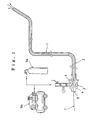
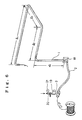
- a coanda spiral flow device 3 is connected to the passage 1 in question through a flexible hose 2 or other means.
- Compressed gas is supplied in the direction for passing a cable or wire into the passage 1 by means of a portable-type compressed gas supply means 5a or 5b via coanda slit 4.
- the cable or wire 7 is inserted into an end introducing inlet 6 of the coanda spiral flow device.
- a pressure release port in the passage 1. By opening this pressure release port prior to passing a cable or wire 7 into the passage 1, it is possible to control the occurrence of a back flow of compressed gas, and thereby to pass the cable or wire through in a stable and smooth manner.
- the location of the pressure release port it is preferred to provide it at a connection between the passage 1 and the coanda spiral flow device 3, for example in the flexible hose 2.
- the cable or wire 7 is automatically conveyed by means of coanda spiral flow into the flexible hose 2 and the passage 1, and passed through at high speed.
- One of the features of the present embodiment is the use of a portable type of compressed gas supply means 5a or 5b.
- a portable type of compressed gas supply means 5a or 5b For instance, an appropriate bomb 5a of air or N2, or an air compressor 5b, can be used.
- the bomb 5a one which has an internal pressure of about 50 to 180 kg/cm2, for example, and which can maintain the pressure of compressed gas supplied to the coanda spiral flow device at a approximately 1 to 10 kg/cm2, is preferred.
- Fig.2 which is an enlarged view of the device illustrated in Fig. 1, the device has an annular coanda slit 4, an inclined surface 9 in the vicinity thereof, and a ventilation distribution chamber 10 for compressed gas between the discharge outlet 8 of the passage and the end introducing inlet 6, through which a cable or wire 7 is inserted.
- devices having a composite unit type of construction as indicated in Figs. 3 and 4 can also be used. Further details of the devices as shown in Figs.3 and 4 are disclosed in European Patent Application No., claiming priority from JP 342347/1989.
- a device comprising three units can be used; namely a first unit A having and end introducing port 6, an outer circumferential inclined or erect surface 11 on the end opposite to the port 11, and a coupling flange 12; a second unit B having a discharge outlet 8, an inner circumferential inclined or curved surface 13 on the end opposite to said outlet, which surface opposes the inclined or erect surface 11 of the first unit A to form a coanda slit 4, a conically tapered inclined surface 9 extending from said inclined or curved surface 13 towards the discharge outlet 8, an annular groove 14 on the outer surface adjacent the surface 13, and a coupling flange 15; and a removable outer peripheral tube unit C having a ventilation inlet 16 which covers the inclined or erect surface 11 and the annular groove 14 and has both ends in close contact with the coupling flanges 12 and 15 of the units A and B, to form a ventilation distribution chamber 10 which communicates with said ventilation inlet 16.
- a conduit 17 is provided to supply compressed gas to the ventilation distribution chamber 10.
- the coanda spiral spiral flow device 3 shown in Fig.5 which is also the subject of European Patent Application No., claiming priority from JP 128289/1990, is a very convenient unit which can be assembled at any work site where a cable or a wire is to be passed through a passage, at any time.
- electric wires, optical fibers or other conductors, or plastic ropes, or other flexible elongate elements can be passed directly through the passage 1.
- a passage of up to about 150m in length not limited to a normal indoor passage 25m to 30m long, can be passed through in a single pass.
- a 22mm-dia. CD pipe was used, and the diameter of the polyethylene rope was 3mm.
- the passage 1 was connected to a flexible hose 2 at joining box 18, and coanda spiral flow device 3 as shown in fig. 5 was linked to said flexible hose 2.
- the flexible hose 2 was 1.5m, long.
- the coanda spiral flow device 3 was provided with an air filter 19, an opening and closing valve 20 and a pressure gauge 21, and compressed air was supplied by a compressor.
- the inclined angle of the inclined surface 9 of the coanda spiral flow device 3 was set at 15°, the angle of the inclined surface 13 was set at 60°, while the coanda slit clearance was 0.18mm.
- a 3 mm-dia. polyethylene rope was passed through a conduit with a diameter of 22 mm and a length of 25m in a similar manner as in EXAMPLE 2. The passing operation was completed in only a few seconds.
- a 2.8 mm-dia. optical fiber cable with a connecting terminal was passed through a conduit with a bore of 22mm and a length of 25m in a similar manner as in EXAMPLE 1.
- a smooth passing was effected in approximately two minutes without any damage to the optical fiber.
- the present invention is not limited to the examples as described above. Various modifications are possible in the type, diameter, bore, length or other details of an element to be passed, a guide, and a passage.
Landscapes
- Engineering & Computer Science (AREA)
- Physics & Mathematics (AREA)
- Mechanical Engineering (AREA)
- Fluid Mechanics (AREA)
- General Engineering & Computer Science (AREA)
- Manufacturing & Machinery (AREA)
- General Physics & Mathematics (AREA)
- Optics & Photonics (AREA)
- Light Guides In General And Applications Therefor (AREA)
- Electric Cable Installation (AREA)
Applications Claiming Priority (4)
| Application Number | Priority Date | Filing Date | Title |
|---|---|---|---|
| JP2128288A JPH0422903A (ja) | 1990-05-18 | 1990-05-18 | 通線方法 |
| JP128288/90 | 1990-05-18 | ||
| JP128289/90 | 1990-05-18 | ||
| JP2128289A JP2517779B2 (ja) | 1990-05-18 | 1990-05-18 | コアンダスパイラルフロ―ユニット |
Publications (2)
| Publication Number | Publication Date |
|---|---|
| EP0457986A1 true EP0457986A1 (fr) | 1991-11-27 |
| EP0457986B1 EP0457986B1 (fr) | 1995-05-03 |
Family
ID=26464007
Family Applications (1)
| Application Number | Title | Priority Date | Filing Date |
|---|---|---|---|
| EP90309895A Expired - Lifetime EP0457986B1 (fr) | 1990-05-18 | 1990-09-10 | Procédé pour introduire un corps flexible et allongé dans un passage |
Country Status (7)
| Country | Link |
|---|---|
| US (1) | US5118226A (fr) |
| EP (1) | EP0457986B1 (fr) |
| KR (1) | KR910020981A (fr) |
| CN (1) | CN1027846C (fr) |
| AU (1) | AU629684B2 (fr) |
| CA (1) | CA2024856C (fr) |
| DE (1) | DE69019142T2 (fr) |
Cited By (3)
| Publication number | Priority date | Publication date | Assignee | Title |
|---|---|---|---|---|
| EP0544388A1 (fr) * | 1991-11-28 | 1993-06-02 | Horii, Kiyoshi | Dispositif d'installation d'un fil |
| EP0606711A1 (fr) * | 1992-10-31 | 1994-07-20 | BICC Public Limited Company | Dispositif d'installation pour une ligne de transmission optique |
| WO2007149080A1 (fr) * | 2006-06-21 | 2007-12-27 | Eastman Chemical Company | Dispositifs et procédés destinés au transport de fibres |
Families Citing this family (23)
| Publication number | Priority date | Publication date | Assignee | Title |
|---|---|---|---|---|
| KR960007907B1 (ko) * | 1991-04-10 | 1996-06-15 | 키요시 호리이 | 통선장치 |
| US5374034A (en) * | 1993-09-02 | 1994-12-20 | Fast Laing Industries, Inc. | Apparatus for installing a line through conduits |
| US5573225A (en) * | 1994-05-06 | 1996-11-12 | Dowell, A Division Of Schlumberger Technology Corporation | Means for placing cable within coiled tubing |
| US5730424A (en) * | 1995-04-14 | 1998-03-24 | Fli Line Tool Corporation | Apparatus for sending a line through a conduit |
| AU5561598A (en) * | 1996-12-11 | 1998-07-03 | Koninklijke Kpn N.V. | Method for inserting a cable-like element into a tube coiled in or on a holder |
| NL1004747C2 (nl) * | 1996-12-11 | 1998-06-15 | Nederland Ptt | Methode en inrichting voor het inbrengen van een kabelvormig element in een op of in een houder opgewonden langgerekte buisvormige omhulling. |
| US6134766A (en) * | 1997-03-24 | 2000-10-24 | Sievert; Thomas M. | Method and apparatus for installing cable-like elements inside pipes |
| US6148925A (en) * | 1999-02-12 | 2000-11-21 | Moore; Boyd B. | Method of making a conductive downhole wire line system |
| US6428246B1 (en) | 2000-06-22 | 2002-08-06 | Sealed Air Corporation | System and method of conveying, storing, and dispensing packing material |
| WO2004005968A2 (fr) * | 2002-07-03 | 2004-01-15 | Sensor Highway Limited | Deploiement a impulsion d'un cable a travers un conduit se trouvant dans un puits |
| US7350291B2 (en) * | 2005-06-30 | 2008-04-01 | Cardiac Pacemakers, Inc. | Method for manufacturing a cable by stringing an element through a sheath |
| US7530810B2 (en) * | 2006-08-30 | 2009-05-12 | Clement Milton A | Dental fixture implantation system and associated method |
| US20080205998A1 (en) * | 2007-02-22 | 2008-08-28 | Bernard Lasko | Pellet Delivery System |
| US8167516B2 (en) * | 2007-02-22 | 2012-05-01 | Bernard Lasko | Pellet Delivery System |
| CN101786550B (zh) * | 2010-02-10 | 2012-02-08 | 无锡三和重工机械有限公司 | 一种干制散货输送管活动接头密封装置 |
| US20130287504A1 (en) * | 2012-07-24 | 2013-10-31 | Harry John Gatley | Method and Apparatus Accelerate Gases Peripherally |
| DE102017115939A1 (de) | 2017-07-14 | 2019-01-17 | Saurer Spinning Solutions Gmbh & Co. Kg | Verfahren zum Betreiben einer Luftspinnvorrichtung, Fadenleitkanal und Luftspinnmaschine umfassend einen solchen Fadenleitkanal |
| ES2718704B2 (es) * | 2018-02-27 | 2022-01-11 | Nortek S A | Boquilla separadora de alta eficiencia |
| CN109578079A (zh) * | 2019-01-28 | 2019-04-05 | 霍州煤电集团有限责任公司 | 一种播种式光纤测温布线装置及其布线方法 |
| CN111313332A (zh) * | 2020-02-20 | 2020-06-19 | 青岛博海建设集团有限公司 | 一种高效气压法室内穿线施工工艺 |
| US11214450B1 (en) * | 2021-03-11 | 2022-01-04 | Cciip Llc | Method of proofing an innerduct/microduct and proofing manifold |
| DE102022101248A1 (de) * | 2022-01-20 | 2023-07-20 | Saurer Technologies GmbH & Co. KG | Fadenzuführvorrichtung, Arbeitsstelle einer Kabliermaschine sowie Verfahren zur Zuführung |
| CN117086607A (zh) * | 2023-08-22 | 2023-11-21 | 广东锦熹智能科技有限公司 | 一种用于热压板的穿线装置 |
Citations (2)
| Publication number | Priority date | Publication date | Assignee | Title |
|---|---|---|---|---|
| US4640576A (en) * | 1984-06-26 | 1987-02-03 | Canada Wire And Cable Limited | Method and apparatus for tubing optical fibers |
| EP0347018A1 (fr) * | 1988-06-17 | 1989-12-20 | Fukuvi Chemical Industry Co., Ltd. | Procédé pour transférer des fibres courtes |
Family Cites Families (14)
| Publication number | Priority date | Publication date | Assignee | Title |
|---|---|---|---|---|
| US2310265A (en) * | 1939-09-18 | 1943-02-09 | Robert P Sweeny | Pneumatic conveying apparatus |
| US2982082A (en) * | 1954-10-20 | 1961-05-02 | British Celanese | Production of voluminous yarn |
| US2924868A (en) * | 1956-09-13 | 1960-02-16 | Eastman Kodak Co | Jet device for blowing yarn and process |
| US3276821A (en) * | 1964-02-28 | 1966-10-04 | Howard C Edwards | Materials handling draft eductor |
| DE3480335D1 (en) * | 1983-08-01 | 1989-12-07 | Horii Kiyoshi | Method and apparatus for the generation and utilization of a spiral gas stream in a pipeline |
| JPS6031437A (ja) * | 1983-08-01 | 1985-02-18 | Kiyoyuki Horii | 螺旋気流による粒塊の輸送方法 |
| JPH0660640B2 (ja) * | 1985-09-09 | 1994-08-10 | 清之 堀井 | 管路に螺旋流体流を生成させる装置 |
| JPH0750967B2 (ja) * | 1986-09-02 | 1995-05-31 | 清之 堀井 | 電線・ケ−ブル貫通用のコアンダスパイラルフロ−装置 |
| JPH0748923B2 (ja) * | 1986-09-02 | 1995-05-24 | 清之 堀井 | 電線・ケ−ブルの貫通方法 |
| JP2506108B2 (ja) * | 1987-04-20 | 1996-06-12 | 住友石炭鉱業株式会社 | 多段コアンダスパイラルフロ−生成装置 |
| JPS6464918A (en) * | 1987-09-03 | 1989-03-10 | Horii Kyoyuki | Staple conveying method |
| JPH0198519A (ja) * | 1987-10-07 | 1989-04-17 | Yamaha Motor Co Ltd | 部品供給ヘツド |
| CA1306241C (fr) * | 1988-08-11 | 1992-08-11 | Nobuo Araki | Appareil servant a l'insertion d'un fil dans un tube |
| JPH0347018A (ja) * | 1989-07-12 | 1991-02-28 | Matsushita Refrig Co Ltd | 生鮮物貯蔵装置 |
-
1990
- 1990-09-07 AU AU62289/90A patent/AU629684B2/en not_active Ceased
- 1990-09-07 CA CA002024856A patent/CA2024856C/fr not_active Expired - Fee Related
- 1990-09-10 KR KR1019900014278A patent/KR910020981A/ko not_active Ceased
- 1990-09-10 DE DE69019142T patent/DE69019142T2/de not_active Expired - Fee Related
- 1990-09-10 US US07/579,322 patent/US5118226A/en not_active Expired - Fee Related
- 1990-09-10 CN CN90108370A patent/CN1027846C/zh not_active Expired - Fee Related
- 1990-09-10 EP EP90309895A patent/EP0457986B1/fr not_active Expired - Lifetime
Patent Citations (2)
| Publication number | Priority date | Publication date | Assignee | Title |
|---|---|---|---|---|
| US4640576A (en) * | 1984-06-26 | 1987-02-03 | Canada Wire And Cable Limited | Method and apparatus for tubing optical fibers |
| EP0347018A1 (fr) * | 1988-06-17 | 1989-12-20 | Fukuvi Chemical Industry Co., Ltd. | Procédé pour transférer des fibres courtes |
Cited By (4)
| Publication number | Priority date | Publication date | Assignee | Title |
|---|---|---|---|---|
| EP0544388A1 (fr) * | 1991-11-28 | 1993-06-02 | Horii, Kiyoshi | Dispositif d'installation d'un fil |
| AU656975B2 (en) * | 1991-11-28 | 1995-02-23 | Kiyoshi Horii | Wire installation device |
| EP0606711A1 (fr) * | 1992-10-31 | 1994-07-20 | BICC Public Limited Company | Dispositif d'installation pour une ligne de transmission optique |
| WO2007149080A1 (fr) * | 2006-06-21 | 2007-12-27 | Eastman Chemical Company | Dispositifs et procédés destinés au transport de fibres |
Also Published As
| Publication number | Publication date |
|---|---|
| DE69019142D1 (de) | 1995-06-08 |
| DE69019142T2 (de) | 1995-08-31 |
| EP0457986B1 (fr) | 1995-05-03 |
| CN1056960A (zh) | 1991-12-11 |
| US5118226A (en) | 1992-06-02 |
| KR910020981A (ko) | 1991-12-20 |
| CA2024856C (fr) | 1999-02-23 |
| CN1027846C (zh) | 1995-03-08 |
| AU6228990A (en) | 1991-11-21 |
| AU629684B2 (en) | 1992-10-08 |
| CA2024856A1 (fr) | 1991-11-19 |
Similar Documents
| Publication | Publication Date | Title |
|---|---|---|
| EP0457986B1 (fr) | Procédé pour introduire un corps flexible et allongé dans un passage | |
| AU615446B2 (en) | Pipeline systems | |
| CA2071159C (fr) | Dispositif de filerie ameliore | |
| AU643554B2 (en) | Device for passing wire | |
| EP0795942A1 (fr) | Réseau de distribution du gaz avec câble de transmission de l'information | |
| EP0456931B1 (fr) | Dispositif d'écoulement à spirale Coanda | |
| FR2740862B1 (fr) | Dispositif pour aspirer un fluide gazeux a travers un conduit pour le rejeter a l'exterieur de celui-ci | |
| JPH06121425A (ja) | 通線方法 | |
| JPH0422903A (ja) | 通線方法 | |
| EP0585902B1 (fr) | Méthode et appareil pour mesurer la longueur des tuyaux | |
| JPH06178419A (ja) | コアンダフロー通線装置 | |
| HU221095B1 (en) | Method of installing pipes | |
| JP2548465B2 (ja) | 通線装置 | |
| JPH0630514A (ja) | 通線方法 | |
| JPH0379492B2 (fr) | ||
| JPH07250410A (ja) | 通線用管路アダプタ | |
| JPS5895565A (ja) | パイプの内面ライニング法 | |
| JPH0549132A (ja) | パイプ・イン・パイプ貫通方法 | |
| JPH01292302A (ja) | 光ファイバの布設方法 | |
| JPH06217433A (ja) | 通線装置 | |
| KR100388782B1 (ko) | 광섬유 케이블을 가스 파이프 내부에 설치하기 위한 장치및 그 방법 | |
| JPH04172403A (ja) | 細径管路への光ファイバ送り込み方法 | |
| JPH034272B2 (fr) | ||
| JPH03144504A (ja) | ケーブルの布設回収方法 | |
| JPH0447613B2 (fr) |
Legal Events
| Date | Code | Title | Description |
|---|---|---|---|
| PUAI | Public reference made under article 153(3) epc to a published international application that has entered the european phase |
Free format text: ORIGINAL CODE: 0009012 |
|
| AK | Designated contracting states |
Kind code of ref document: A1 Designated state(s): DE FR GB |
|
| 17P | Request for examination filed |
Effective date: 19911204 |
|
| 17Q | First examination report despatched |
Effective date: 19931208 |
|
| GRAA | (expected) grant |
Free format text: ORIGINAL CODE: 0009210 |
|
| AK | Designated contracting states |
Kind code of ref document: B1 Designated state(s): DE FR GB |
|
| REF | Corresponds to: |
Ref document number: 69019142 Country of ref document: DE Date of ref document: 19950608 |
|
| ET | Fr: translation filed | ||
| PLBE | No opposition filed within time limit |
Free format text: ORIGINAL CODE: 0009261 |
|
| STAA | Information on the status of an ep patent application or granted ep patent |
Free format text: STATUS: NO OPPOSITION FILED WITHIN TIME LIMIT |
|
| 26N | No opposition filed | ||
| REG | Reference to a national code |
Ref country code: GB Ref legal event code: IF02 |
|
| PGFP | Annual fee paid to national office [announced via postgrant information from national office to epo] |
Ref country code: FR Payment date: 20020827 Year of fee payment: 13 |
|
| PGFP | Annual fee paid to national office [announced via postgrant information from national office to epo] |
Ref country code: GB Payment date: 20020905 Year of fee payment: 13 |
|
| PGFP | Annual fee paid to national office [announced via postgrant information from national office to epo] |
Ref country code: DE Payment date: 20021028 Year of fee payment: 13 |
|
| PG25 | Lapsed in a contracting state [announced via postgrant information from national office to epo] |
Ref country code: GB Free format text: LAPSE BECAUSE OF NON-PAYMENT OF DUE FEES Effective date: 20030910 |
|
| PG25 | Lapsed in a contracting state [announced via postgrant information from national office to epo] |
Ref country code: DE Free format text: LAPSE BECAUSE OF NON-PAYMENT OF DUE FEES Effective date: 20040401 |
|
| GBPC | Gb: european patent ceased through non-payment of renewal fee |
Effective date: 20030910 |
|
| PG25 | Lapsed in a contracting state [announced via postgrant information from national office to epo] |
Ref country code: FR Free format text: LAPSE BECAUSE OF NON-PAYMENT OF DUE FEES Effective date: 20040528 |
|
| REG | Reference to a national code |
Ref country code: FR Ref legal event code: ST |