EP0458224A1 - Dispositif d'étranglement en forme de segment commandé par flotteur - Google Patents
Dispositif d'étranglement en forme de segment commandé par flotteur Download PDFInfo
- Publication number
- EP0458224A1 EP0458224A1 EP91108071A EP91108071A EP0458224A1 EP 0458224 A1 EP0458224 A1 EP 0458224A1 EP 91108071 A EP91108071 A EP 91108071A EP 91108071 A EP91108071 A EP 91108071A EP 0458224 A1 EP0458224 A1 EP 0458224A1
- Authority
- EP
- European Patent Office
- Prior art keywords
- float
- contactor
- throttle
- control according
- underwater
- Prior art date
- Legal status (The legal status is an assumption and is not a legal conclusion. Google has not performed a legal analysis and makes no representation as to the accuracy of the status listed.)
- Granted
Links
- XLYOFNOQVPJJNP-UHFFFAOYSA-N water Substances O XLYOFNOQVPJJNP-UHFFFAOYSA-N 0.000 claims abstract description 17
- 230000001105 regulatory effect Effects 0.000 claims abstract description 9
- 238000005303 weighing Methods 0.000 claims description 17
- 238000009825 accumulation Methods 0.000 claims description 13
- 238000011010 flushing procedure Methods 0.000 claims description 10
- 230000000694 effects Effects 0.000 claims description 9
- 239000007788 liquid Substances 0.000 claims description 3
- 230000000630 rising effect Effects 0.000 claims description 2
- 230000008878 coupling Effects 0.000 claims 2
- 238000010168 coupling process Methods 0.000 claims 2
- 238000005859 coupling reaction Methods 0.000 claims 2
- 238000011144 upstream manufacturing Methods 0.000 abstract description 4
- 230000033228 biological regulation Effects 0.000 description 4
- 238000013016 damping Methods 0.000 description 4
- 230000001419 dependent effect Effects 0.000 description 4
- 239000010865 sewage Substances 0.000 description 3
- 230000001914 calming effect Effects 0.000 description 2
- 230000004308 accommodation Effects 0.000 description 1
- 230000005540 biological transmission Effects 0.000 description 1
- 238000004140 cleaning Methods 0.000 description 1
- 239000000356 contaminant Substances 0.000 description 1
- 230000001276 controlling effect Effects 0.000 description 1
- 230000007423 decrease Effects 0.000 description 1
- 238000009434 installation Methods 0.000 description 1
- 230000014759 maintenance of location Effects 0.000 description 1
- 239000002184 metal Substances 0.000 description 1
- 238000000034 method Methods 0.000 description 1
- 230000000284 resting effect Effects 0.000 description 1
- 239000002352 surface water Substances 0.000 description 1
- 239000000725 suspension Substances 0.000 description 1
- 230000009182 swimming Effects 0.000 description 1
Images

Classifications
-
- E—FIXED CONSTRUCTIONS
- E03—WATER SUPPLY; SEWERAGE
- E03F—SEWERS; CESSPOOLS
- E03F5/00—Sewerage structures
- E03F5/10—Collecting-tanks; Equalising-tanks for regulating the run-off; Laying-up basins
- E03F5/105—Accessories, e.g. flow regulators or cleaning devices
- E03F5/107—Active flow control devices, i.e. moving during flow regulation
-
- E—FIXED CONSTRUCTIONS
- E02—HYDRAULIC ENGINEERING; FOUNDATIONS; SOIL SHIFTING
- E02B—HYDRAULIC ENGINEERING
- E02B7/00—Barrages or weirs; Layout, construction, methods of, or devices for, making same
- E02B7/20—Movable barrages; Lock or dry-dock gates
- E02B7/205—Barrages controlled by the variations of the water level; automatically functioning barrages
-
- G—PHYSICS
- G05—CONTROLLING; REGULATING
- G05D—SYSTEMS FOR CONTROLLING OR REGULATING NON-ELECTRIC VARIABLES
- G05D7/00—Control of flow
- G05D7/01—Control of flow without auxiliary power
- G05D7/0166—Control of flow without auxiliary power the sensing element being a float or a ball placed outside the flow path to be controlled
Definitions
- the disadvantage is that in the event of later dirt deposits in front of the throttle bodies, there is no longer any flushing, rather, the further rising float regulates an additional closing process.
- the known discharge flow controller can therefore not be used for polluted water or for smaller drains, since a free-rinsing effect only occurs once after practically complete emptying of the pool.
- a discharge control is known from DE-PS 30 38 098, in which the discharge flow is completely detected by a weighing channel suspended from a lever system.
- the weighing channel is moved by the forces contained in the flowing flow and thus an upstream throttle element is adjusted until the state of equilibrium is reached between the forces of the flowing liquid and a compensating member that relieves the weighing channel. Due to its mode of operation, the weighing channel is subject to certain restrictions and structural conditions, because a relatively large overall length and also a certain cross-sectional depth are necessary to record the weight.
- this object is achieved in that a part of the drive connection between the OW float and the UW throttle element is a first correction device which takes into account the dependence of the outflow quantity on the accumulation level in the container, that in front of the UW throttle element there is a swimming chamber containing a UW float and an inlet channel arranged between the tank outlet and the float chamber an adjustable contactor is provided that the UW float is connected to the contactor in opposite directions via a linkage so that a predetermined artificial accumulation height in the float chamber is maintained by the opening width in the inlet channel as soon as the pool drain a certain value, eg. B. 2 x Q TW exceeds that a responding to blockages in front of the UW throttle body emergency release device is coupled to the UW float and acts opening on the actuating linkage of the UW throttle body.
- a certain value eg. B. 2 x Q TW
- An important feature is the special way in which the drainage control according to the invention copes with the risk of clogging, especially in the case of small flow rates and low slopes, in that maintenance-free effects are achieved by automatic flushing effects.
- Deposits accumulating in front of the throttle element and leading to blockages are eliminated by the fact that the underwater float element automatically opens via the underwater float arranged in the float chamber when a certain intended accumulation height is exceeded.
- the segment contactor and its correction curve which is dependent on the fill level in the storage container, ensure that the segment contactor has sufficient supply opening in the event of a blockage on the outlet orifice leaves wide open to ensure the flushing effect. Any blockages that may build up on the segment contactor are also automatically removed when the level in the float chamber drops, with the then increasing weight of the underwater float and the resulting lifting of the segment contactor.
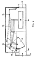
- a second basic embodiment of the discharge control according to the invention, four of the most important basic elements of the first described embodiment are also used, namely the segment contactor arranged in the inlet channel, the float arranged in the re-designed float chamber, and the segment contactor via a weighing beam is adjustable in opposite directions, further a downstream throttle orifice arranged in front of the outlet of the shaft housing or the float chamber for precise drain control and a stop curve taking into account the outflow laws from the storage container for the adjustment of the underwater orifice, which is arranged on the segment contactor for sensitive regulation of the underwater orifice and such a course has that the actuating linkage of the underwater screen, which is limited in its movement by the stop curve, ensures the same adjustment of the segment contactor and screen both when closing and when opening.
- an emergency release device which is automatically actuated when the water level increases in the float chamber and which couples the float movement with the orifice opening movement is used.
- a damping device eg, for damping the regulating movements of the segment contactor.
- a damping cylinder is provided.
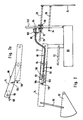
- a float 36 is provided on the upper water level 12 of a storage container 10, which is connected via a connecting rod 38 to a pivot shaft 40 mounted in the side wall of the shaft housing 14.
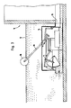
- the Z. B. existing metal shaft housing 14 can be set up dry in a shaft, not shown, independent of the basin or, according to FIG. 3, placed on the bottom of the storage container to save space or be encapsulated, in accordance with FIG. 3 z. B. in front of the storage container drain 16.
- an underwater throttle element 24 is arranged in the form of a vertically guided throttle diaphragm.
- the diaphragm is guided in parallel via a linkage 26 leading upwards and preferably via two parallel guide links 28, 30 (FIG. 2).
- the links 28, 30 have fixed pivot axes 32, 34.
- the upper link 28 is beyond its pivot axis 32 at 29 extended and is guided there on a correction curve 46 which takes into account the outflow laws for the container stowage height.
- the type of guide curve shown and the connection to the underwater throttle element 24 is schematic and can be replaced in practice by other measures having the same effect.
- the curve 46 is generally guided horizontally in guides, not shown, within the shaft housing 14 in such a way that the free end 29 of the actuating lever 28 on the curve 46 moves to the right and thus to the steep region of the curve 46 as the accumulation level in the container 10 decreases to open the underwater aperture 24.
- An inlet duct 50 adjoins the shaft inlet 18, in which a segment contactor 52 is mounted so as to be pivotable about a horizontal axis 54.
- the segment contactor 52 is attached to a weighing beam at point 58 by means of a handlebar or a bracket 56.
- the weighing beam consists of two normally rigid core 72 and 74, which on a common pivot axis 84 of a fixed bearing support 76 are pivotable.
- the partial link 70 forming the right end of the weighing beam is pivotally connected to an upper extension 68 of a float 66.
- the float 66 is preferably guided parallel to itself by the parallel links 70, 72.
- the suspension of the segment contactor 52 comprises a correction or retention curve 60, on which a slide roller or a sliding block 58 of the link 56 is guided or held in such a way that the opening value in the inlet channel 50 is maintained or not reduced, which corresponds to the accumulation height in the storage container 10 is assigned to maintain the desired level of artificial build-up in the float chamber.
- the correction curve 60 wins e.g. B. Significance if, in the event of a blockage in front of the aperture 24, the accumulation in the float chamber 64 rises and the segment throttle should actually move in the closing direction due to the upward movement of the UW float.
- FIG. 2 shows, as a variant of this emergency release device, an actuating rod 100 which is articulated on the upper side of the float 66 and which has a toothing, for example a locking toothing, and is guided in a sleeve 98 connected to the handlebar 28.
- the locking toothing is assigned a locking pawl 94, which is pivotally mounted on a holder 96 extending from the sleeve 98 with its upper end and is at its lower end under the action of a biasing spring 102 supported on the holder 96, which engages the locking pawl with the locking toothing tried to press.
- the pawl 94 is connected to the wire rope 92 of a Bowden train 88.
- the upper parallel link 70 of the float guide forms the right-hand partial link of the weighing beam, which is pivotally connected to the segment contactor 52 together with the left-hand partial link 74 about the fixed pivot point 84.
- the two partial links 70, 74 are in Fig. 2 under the load of the attached segment contactor 52 in the stretched state, the z. B. is maintained by the stop 86 on the partial link 74. If the downward movement of the segment contactor 52 made possible by the upward movement of the float 66 is limited or prevented by the sliding block 58 resting against the correction curve 60, the partial links 70, 74 of the weighing beam according to FIG.
- the guide bracket 110 is connected to the wire rope 92 of the Bowden cable via an extension 106, the wire rope due to the pretension spring 72 moving together with the latch 102 to the right in FIG. 2 and the upward movement of the float 66 via the pawl engagement the actuating rod 28 attached sleeve 98 in a rectified upward movement of the diaphragm 24.
- the stopper 104 causes the catch to disengage from the actuating rod 100.
- the outlet-side diaphragm 24 is briefly opened by the application of an assistant, e.g. B. with the help of an electrically operated magnet or a hydraulic or pneumatic cylinder, the period of time keeping the aperture open is adjusted according to local conditions or needs. This also applies to the frequency of triggering such Flushing pulses caused by a timer, e.g. B. a timer is set.
- a float In order to temporarily open the diaphragm without external energy, a float can be coupled in, and in an embodiment not shown, the float 66 is used for this.
- the diaphragm slide 24 is pulled up by a motor engaging the rod 26, which, for. B. has a rope over a roller or drum with an attached drive weight. Since the float 66 drops in accordance with the function of the discharge control when the float chamber 64 is emptied, it pulls the rope with the drive weight again with this lowering movement by means of a suitable connection and / or drive transmission.
- an independent float can be provided for performing the elevator function for the cable motor and the timing element, the mechanical or hydraulic timing element triggering the wound-up cable motor to open the cover 24 after an adjustable period of time.
Landscapes
- Engineering & Computer Science (AREA)
- Structural Engineering (AREA)
- General Engineering & Computer Science (AREA)
- Health & Medical Sciences (AREA)
- Automation & Control Theory (AREA)
- General Physics & Mathematics (AREA)
- Mechanical Engineering (AREA)
- Civil Engineering (AREA)
- Physics & Mathematics (AREA)
- Life Sciences & Earth Sciences (AREA)
- Hydrology & Water Resources (AREA)
- Public Health (AREA)
- Water Supply & Treatment (AREA)
- Float Valves (AREA)
- Other Liquid Machine Or Engine Such As Wave Power Use (AREA)
- Barrages (AREA)
Applications Claiming Priority (2)
| Application Number | Priority Date | Filing Date | Title |
|---|---|---|---|
| DE4016376 | 1990-05-21 | ||
| DE4016376A DE4016376C2 (de) | 1990-05-21 | 1990-05-21 | Abflußregelung für Regenspeicherbecken |
Publications (2)
| Publication Number | Publication Date |
|---|---|
| EP0458224A1 true EP0458224A1 (fr) | 1991-11-27 |
| EP0458224B1 EP0458224B1 (fr) | 1994-09-28 |
Family
ID=6406906
Family Applications (1)
| Application Number | Title | Priority Date | Filing Date |
|---|---|---|---|
| EP91108071A Expired - Lifetime EP0458224B1 (fr) | 1990-05-21 | 1991-05-18 | Dispositif d'étranglement en forme de segment commandé par flotteur |
Country Status (3)
| Country | Link |
|---|---|
| EP (1) | EP0458224B1 (fr) |
| AT (1) | ATE112350T1 (fr) |
| DE (1) | DE4016376C2 (fr) |
Cited By (10)
| Publication number | Priority date | Publication date | Assignee | Title |
|---|---|---|---|---|
| WO1994010398A1 (fr) * | 1992-11-04 | 1994-05-11 | Peter John Higgins | Regulateur d'ecoulement d'eau de pluie |
| EP0627530A1 (fr) * | 1993-05-11 | 1994-12-07 | BGU BAUGESELLSCHAFT FÜR UMWELTSCHUTZANLAGEN mbH | Dispositif de contrôle de débit |
| EP1069252A1 (fr) * | 1999-07-15 | 2001-01-17 | Bionik GmbH - Innovative Technik für die Umwelt | Dispoitif de contrôle de débit pour réservoir de retenue des eaux pluviales |
| WO2001088292A1 (fr) * | 2000-05-17 | 2001-11-22 | GÜTHLER, Renate | Procede et dispositif pour reguler des ecoulements et/ou epurer des canalisations |
| WO2003012209A1 (fr) * | 2001-08-03 | 2003-02-13 | Trojan Technologies Inc. | Systeme de regulation du niveau de liquide |
| US6663318B2 (en) | 2001-08-03 | 2003-12-16 | Trojan Technologies, Inc. | Fluid level control system |
| FR2847603A1 (fr) * | 2002-11-22 | 2004-05-28 | S Saint Dizier Environnement S | Regulateur de debit a decolmatage automatique |
| EP1845210A3 (fr) * | 2006-04-15 | 2007-12-19 | REHAU AG + Co | Commutateur avec restricteur de débit |
| CN112064589A (zh) * | 2020-09-18 | 2020-12-11 | 青海师范大学 | 一种用于水质净化的可透水生态透水溢流坝 |
| CN112281759A (zh) * | 2020-10-20 | 2021-01-29 | 重庆大学 | 一种用于地下及临水建筑的智能化自动控制防洪系统 |
Families Citing this family (2)
| Publication number | Priority date | Publication date | Assignee | Title |
|---|---|---|---|---|
| DE20021617U1 (de) * | 2000-12-21 | 2002-05-02 | BIONIK GmbH - Innovative Technik für die Umwelt, 65232 Taunusstein | Spülklappe an einer Spülkammer eines Flüssigkeitsspeicherraumes |
| FR3121192B1 (fr) * | 2021-03-25 | 2023-10-06 | Bernard Sikora | Dispositif de régulation d’un flux d’effluent d’une canalisation |
Citations (5)
| Publication number | Priority date | Publication date | Assignee | Title |
|---|---|---|---|---|
| DE3038098A1 (de) * | 1980-10-09 | 1982-05-13 | Karl 7891 Ühlingen Kraus | Abflussregelung fuer fluessigkeitsbehaelter |
| DE3108440A1 (de) * | 1981-03-06 | 1982-12-09 | Karl-Heinz 7114 Windischenbach Göhre | Abwasserabflussmengenbegrenzung - schwimmer/schieber-steuerung |
| DE3418347A1 (de) * | 1984-05-17 | 1985-11-21 | Lothar Dipl.-Ing. 6204 Taunusstein Steinhardt | Abflussmengenregler |
| DE3822555A1 (de) * | 1988-01-25 | 1989-08-03 | Giehl Klaus Ulrich | Drosselvorrichtung fuer kanalisationsanlagen |
| DE3914702A1 (de) * | 1989-05-04 | 1990-11-08 | Steinhardt Lothar | Abflussmengenregler |
Family Cites Families (1)
| Publication number | Priority date | Publication date | Assignee | Title |
|---|---|---|---|---|
| DE3418348C2 (de) * | 1984-05-17 | 1994-12-01 | Steinhardt Lothar | Abflußmengenregler |
-
1990
- 1990-05-21 DE DE4016376A patent/DE4016376C2/de not_active Expired - Fee Related
-
1991
- 1991-05-18 AT AT91108071T patent/ATE112350T1/de not_active IP Right Cessation
- 1991-05-18 EP EP91108071A patent/EP0458224B1/fr not_active Expired - Lifetime
Patent Citations (5)
| Publication number | Priority date | Publication date | Assignee | Title |
|---|---|---|---|---|
| DE3038098A1 (de) * | 1980-10-09 | 1982-05-13 | Karl 7891 Ühlingen Kraus | Abflussregelung fuer fluessigkeitsbehaelter |
| DE3108440A1 (de) * | 1981-03-06 | 1982-12-09 | Karl-Heinz 7114 Windischenbach Göhre | Abwasserabflussmengenbegrenzung - schwimmer/schieber-steuerung |
| DE3418347A1 (de) * | 1984-05-17 | 1985-11-21 | Lothar Dipl.-Ing. 6204 Taunusstein Steinhardt | Abflussmengenregler |
| DE3822555A1 (de) * | 1988-01-25 | 1989-08-03 | Giehl Klaus Ulrich | Drosselvorrichtung fuer kanalisationsanlagen |
| DE3914702A1 (de) * | 1989-05-04 | 1990-11-08 | Steinhardt Lothar | Abflussmengenregler |
Cited By (12)
| Publication number | Priority date | Publication date | Assignee | Title |
|---|---|---|---|---|
| WO1994010398A1 (fr) * | 1992-11-04 | 1994-05-11 | Peter John Higgins | Regulateur d'ecoulement d'eau de pluie |
| EP0627530A1 (fr) * | 1993-05-11 | 1994-12-07 | BGU BAUGESELLSCHAFT FÜR UMWELTSCHUTZANLAGEN mbH | Dispositif de contrôle de débit |
| EP1069252A1 (fr) * | 1999-07-15 | 2001-01-17 | Bionik GmbH - Innovative Technik für die Umwelt | Dispoitif de contrôle de débit pour réservoir de retenue des eaux pluviales |
| WO2001088292A1 (fr) * | 2000-05-17 | 2001-11-22 | GÜTHLER, Renate | Procede et dispositif pour reguler des ecoulements et/ou epurer des canalisations |
| WO2003012209A1 (fr) * | 2001-08-03 | 2003-02-13 | Trojan Technologies Inc. | Systeme de regulation du niveau de liquide |
| US6663318B2 (en) | 2001-08-03 | 2003-12-16 | Trojan Technologies, Inc. | Fluid level control system |
| US6719491B2 (en) | 2001-08-03 | 2004-04-13 | Trojan Technologies Inc. | Fluid level control system |
| FR2847603A1 (fr) * | 2002-11-22 | 2004-05-28 | S Saint Dizier Environnement S | Regulateur de debit a decolmatage automatique |
| EP1426507A1 (fr) * | 2002-11-22 | 2004-06-09 | S.A.S. Saint Dizier Environnement | Régulateur de débit à décolmatage automatique |
| EP1845210A3 (fr) * | 2006-04-15 | 2007-12-19 | REHAU AG + Co | Commutateur avec restricteur de débit |
| CN112064589A (zh) * | 2020-09-18 | 2020-12-11 | 青海师范大学 | 一种用于水质净化的可透水生态透水溢流坝 |
| CN112281759A (zh) * | 2020-10-20 | 2021-01-29 | 重庆大学 | 一种用于地下及临水建筑的智能化自动控制防洪系统 |
Also Published As
| Publication number | Publication date |
|---|---|
| DE4016376A1 (de) | 1991-12-12 |
| DE4016376C2 (de) | 1994-01-27 |
| EP0458224B1 (fr) | 1994-09-28 |
| ATE112350T1 (de) | 1994-10-15 |
Similar Documents
| Publication | Publication Date | Title |
|---|---|---|
| EP0458224A1 (fr) | Dispositif d'étranglement en forme de segment commandé par flotteur | |
| DE3915076C2 (fr) | ||
| DE3510171A1 (de) | Fluessigkeitsrueckhalteeinrichtung fuer den einbau in einen fluessigkeitsspeicherraum | |
| DE3038098A1 (de) | Abflussregelung fuer fluessigkeitsbehaelter | |
| EP0293513B1 (fr) | Procédé pour activer le mécanisme de fermeture d'une soupape commandée par flotteur d'une chambre de rinçage pour rincer un réservoir de stockage de liquide et dispositif pour appliquer ce procédé | |
| DE4212303A1 (de) | Einrichtung zur steuerung von ueberfallmengen und wasserspiegellagen in wasseranlagen | |
| DE3202354A1 (de) | Vorrichtung fuer den fluessigkeitsabzug aus becken o.dgl. | |
| DE3817444A1 (de) | Schwimmergesteuerte regelvorrichtung zur veraenderung des durchflussquerschnittes der auslaufoeffnung eines fluessigkeitsbehaelters, insbesondere eines regenrueckhaltebeckens | |
| DE3108440C2 (de) | Drosselschacht zur Steuerung des Abflusses aus einer Regenwasserrückhalteanlage | |
| DE3403072C2 (de) | Regelvorrichtung für eine Abflußmenge | |
| EP0503209B1 (fr) | Dispositif de régulation pour modifier la section de passage d'un orifice de sortie d'un récipient d'égalisation, en particulier d'un réservoir de retenue d'eaux pluviales | |
| DE3051024C2 (fr) | ||
| AT396493B (de) | Abflussregelung für speicherbecken | |
| EP3219864B1 (fr) | Récipient de liquide comprenant une soupape die vidange et utilisation correspondante pour produire une vague de rinçage | |
| DE2911780A1 (de) | Automatisch schwerkraftgesteuertes ueberlaufbauwerk, insbesondere in entwaesserungskanaelen der stadtentwaesserung | |
| EP1069252B1 (fr) | Dispoitif de contrôle de débit pour réservoir de retenue des eaux pluviales | |
| EP0565483B1 (fr) | Bassin dans une installation d'eaux usées | |
| DE19742594C2 (de) | Auslaufregler | |
| DE29805781U1 (de) | Drosselgarnitur für Abwasserpufferbecken | |
| DE8717652U1 (de) | Abflußregler für Stauräume in Kanalsystemen | |
| EP0619131B1 (fr) | Séparateur de liquide léger avec fermeture automatique | |
| DE29604004U1 (de) | Vorrichtung zum stoßweisen Entleeren eines Flüssigkeitsstauraumes, insbesondere in einem Kanalisationsnetz | |
| CH657461A5 (de) | Schwimmergesteuerte regelvorrichtung zur veraenderung des querschnittes eines rohres. | |
| DE8508382U1 (de) | Flüssigkeitsrückhalteeinrichtung für den Einbau in einen Flüssigkeitsspeicherraum | |
| DE3630914C1 (en) | Apparatus for improving the response behaviour of a mechanical discharge control system |
Legal Events
| Date | Code | Title | Description |
|---|---|---|---|
| PUAI | Public reference made under article 153(3) epc to a published international application that has entered the european phase |
Free format text: ORIGINAL CODE: 0009012 |
|
| AK | Designated contracting states |
Kind code of ref document: A1 Designated state(s): AT CH FR LI |
|
| 17P | Request for examination filed |
Effective date: 19920525 |
|
| 17Q | First examination report despatched |
Effective date: 19921123 |
|
| GRAA | (expected) grant |
Free format text: ORIGINAL CODE: 0009210 |
|
| AK | Designated contracting states |
Kind code of ref document: B1 Designated state(s): AT CH FR LI |
|
| REF | Corresponds to: |
Ref document number: 112350 Country of ref document: AT Date of ref document: 19941015 Kind code of ref document: T |
|
| ET | Fr: translation filed | ||
| PLBE | No opposition filed within time limit |
Free format text: ORIGINAL CODE: 0009261 |
|
| STAA | Information on the status of an ep patent application or granted ep patent |
Free format text: STATUS: NO OPPOSITION FILED WITHIN TIME LIMIT |
|
| 26N | No opposition filed | ||
| PGFP | Annual fee paid to national office [announced via postgrant information from national office to epo] |
Ref country code: CH Payment date: 19990629 Year of fee payment: 9 |
|
| PG25 | Lapsed in a contracting state [announced via postgrant information from national office to epo] |
Ref country code: LI Free format text: LAPSE BECAUSE OF NON-PAYMENT OF DUE FEES Effective date: 20000531 Ref country code: CH Free format text: LAPSE BECAUSE OF NON-PAYMENT OF DUE FEES Effective date: 20000531 |
|
| REG | Reference to a national code |
Ref country code: CH Ref legal event code: PL |
|
| PGFP | Annual fee paid to national office [announced via postgrant information from national office to epo] |
Ref country code: FR Payment date: 20030509 Year of fee payment: 13 |
|
| PG25 | Lapsed in a contracting state [announced via postgrant information from national office to epo] |
Ref country code: FR Free format text: LAPSE BECAUSE OF NON-PAYMENT OF DUE FEES Effective date: 20050131 |
|
| REG | Reference to a national code |
Ref country code: FR Ref legal event code: ST |
|
| PGFP | Annual fee paid to national office [announced via postgrant information from national office to epo] |
Ref country code: AT Payment date: 20050510 Year of fee payment: 15 |
|
| PG25 | Lapsed in a contracting state [announced via postgrant information from national office to epo] |
Ref country code: AT Free format text: LAPSE BECAUSE OF NON-PAYMENT OF DUE FEES Effective date: 20060518 |