EP0458334B1 - Lecteur de codes à bâtonnets - Google Patents
Lecteur de codes à bâtonnets Download PDFInfo
- Publication number
- EP0458334B1 EP0458334B1 EP91108358A EP91108358A EP0458334B1 EP 0458334 B1 EP0458334 B1 EP 0458334B1 EP 91108358 A EP91108358 A EP 91108358A EP 91108358 A EP91108358 A EP 91108358A EP 0458334 B1 EP0458334 B1 EP 0458334B1
- Authority
- EP
- European Patent Office
- Prior art keywords
- scan
- laser beam
- bar code
- rotational
- read window
- Prior art date
- Legal status (The legal status is an assumption and is not a legal conclusion. Google has not performed a legal analysis and makes no representation as to the accuracy of the status listed.)
- Expired - Lifetime
Links
Images




Classifications
-
- G—PHYSICS
- G06—COMPUTING OR CALCULATING; COUNTING
- G06K—GRAPHICAL DATA READING; PRESENTATION OF DATA; RECORD CARRIERS; HANDLING RECORD CARRIERS
- G06K7/00—Methods or arrangements for sensing record carriers, e.g. for reading patterns
- G06K7/10—Methods or arrangements for sensing record carriers, e.g. for reading patterns by electromagnetic radiation, e.g. optical sensing; by corpuscular radiation
- G06K7/10544—Methods or arrangements for sensing record carriers, e.g. for reading patterns by electromagnetic radiation, e.g. optical sensing; by corpuscular radiation by scanning of the records by radiation in the optical part of the electromagnetic spectrum
- G06K7/10821—Methods or arrangements for sensing record carriers, e.g. for reading patterns by electromagnetic radiation, e.g. optical sensing; by corpuscular radiation by scanning of the records by radiation in the optical part of the electromagnetic spectrum further details of bar or optical code scanning devices
- G06K7/10861—Methods or arrangements for sensing record carriers, e.g. for reading patterns by electromagnetic radiation, e.g. optical sensing; by corpuscular radiation by scanning of the records by radiation in the optical part of the electromagnetic spectrum further details of bar or optical code scanning devices sensing of data fields affixed to objects or articles, e.g. coded labels
- G06K7/10871—Methods or arrangements for sensing record carriers, e.g. for reading patterns by electromagnetic radiation, e.g. optical sensing; by corpuscular radiation by scanning of the records by radiation in the optical part of the electromagnetic spectrum further details of bar or optical code scanning devices sensing of data fields affixed to objects or articles, e.g. coded labels randomly oriented data-fields, code-marks therefore, e.g. concentric circles-code
-
- G—PHYSICS
- G06—COMPUTING OR CALCULATING; COUNTING
- G06K—GRAPHICAL DATA READING; PRESENTATION OF DATA; RECORD CARRIERS; HANDLING RECORD CARRIERS
- G06K7/00—Methods or arrangements for sensing record carriers, e.g. for reading patterns
- G06K7/10—Methods or arrangements for sensing record carriers, e.g. for reading patterns by electromagnetic radiation, e.g. optical sensing; by corpuscular radiation
Definitions
- the present invention relates to a bar code reading apparatus according to the preamble of claim 1, Such a bar code reading apparatus is known from JP-A-01048017.
- This apparatus has a structure as shown in Figs. 2 and 3.
- a laser beam from a laser beam source 21 travels through a collimation 22, is reflected by optical-path change mirrors 23 and 24, passes a hole 25a of a perforated lens 25, and is reflected by a polygon rotational mirror 26 for scanning.
- the scan laser beam is reflected by a single fixed horizontal scan mirror 27 to become a group of horizontal scan beams, which are in turn emitted outside through a read window 30.
- the scan laser beam is also reflected by two fixed oblique scan mirrors 28 1 and 28 2 , becoming two groups of oblique scan beams, which are also irradiated outside through the read window 30.
- the scan laser beam is further reflected by two fixed vertical scan mirrors 29 1 and 29 2 , providing two groups of vertical scan beams, which in turn leave outside through the read window 30.
- a laser beam emitted from a laser beam source disposed in the casing enters a converging lens, after refrected by multiple optical-path change mirrors, to be converged into a small beam spot at a predetermined focus position. Then, the laser beam is reflected by a rotational scan mirror, becoming multiple scan beams, which are in turn irradiated outward from the read window.
- the scan beams are normally emanated as five groups of beams, and when any one of the beams crosses the bar code affixed to an object moving outside the read window, modulated reflection light produced there enters a light-receiving lens through the same path as used for emission of the laser beam, and is then received at a light-receiving element.
- the length of the scan lines is proportional to the distance to a bar code from the scan center of the polygon rotational mirror, however, it is difficult to make the scan lines longer for the conventional compact bar code reading apparatus.
- the time to produce a series of scan lines can of course be shortened by increasing the rotational velocity of the polygon rotational mirror.
- this method also increases the linear velocity of the scan beams, so that a decoder for decoding binary information acquired from the output of a light-receiving element, which receives reflection light from the bar code, cannot follow the increased speed. In this respect, shortening the time to generate a series of scan lines is limited.
- the bar code reading apparatus of the present invention can read a bar code even in four groups of scan areas with the same bar-code reading performance as acquired in the case of five scan areas of the conventional apparatus. This feature can reduce the number of required optical components as well as can make the overall apparatus compact.
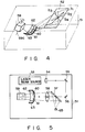
- a read window 52 is provided on the top of a casing 51.
- a laser beam source 53 emits a laser beam.
- the converging optical system 54 converges the laser beam from the laser beam source 53.
- the optical-path change mirrors 55 and 56 change the optical path of the converged laser beam.
- the perforated mirror 57 and perforated lens 58 permit the laser beam, coming from the optical-path change mirrors 55 and 56, to pass through holes formed in their center portions.
- the rotational scan mirror 59 reflect the laser beam having passed through this perforated lens 58 and scans with the laser beam.
- the rotational scan mirror 59 is designed to be a polygonal prism, for example, quadratic prism, with a rotational center axis 59a having its upper portion tilted in the casing 51 in the direction of a normal plane with respect to the read window 52 (i.e., a plane normal to the read window) toward where the read window 52 is provided.
- the mirror 59 reflects an incident laser beam in the opposite direction to the top side of the casing 51 where the read window 52 is provided or obliquely downward to scan with it.
- the individual sides of the mirror 59 have slightly different inclination angles in order to acquire approximately parallel four scan lines in each scan line group.
- Four fixed scan mirrors 60, 61, 62 and 63 are arranged at a lower portion in the casing 51 to receive the reflection beam from the rotational scan mirror 59.
- the fixed scan mirror 60-63 reflects the reflection beam from the rotational scan mirror 59 to produce four groups of laser beams which scan in four direction outward through the read window 52 toward the normal plane to the read window plane.
- the fixed scan mirrors 60 and 61 produce two groups of oblique scan lines b 1 and b 2 , while the fixed scan mirrors 62 and 63 provide two groups of nearly vertical scan lines b 3 and b 4 , as shown in Fig. 1.
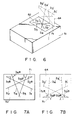
- the fixed scan mirrors 60 and 61 are arranged as shown in Fig. 4 in such a way that the oblique scan lines b 1 and b 2 will have relatively obtuse angles to the horizontal direction on the normal plane 64 as shown in Fig. 6.
- the fixed scan mirrors 62 and 63 are arranged as shown in Fig. 4 so that the nearly vertical scan lines b 3 and b 4 will become approximately perpendicular to the normal plane 64 as shown in Fig. 6.
- those fixed scan mirrors 60-63 are arranged so that four groups of scan lines b 1 to b 4 in the plane of the read window 52 become b 1 ', b 2 ', b 3 ' and b 4 ' on the normal plane 64.
- each scan line group consists of four nearly parallel scan beams, so that the optical system of this embodiment provides sixteen scan beams in total.
- Reflection light obtained by reflection of the scan beams at a bar code outside the read window 52 is received by a light-receiving element 65 after passing through the fixed scan mirrors 60-63, the rotational scan mirror 59, the perforated lens 58 and the perforated mirror 57 in the named order, and is supplied to signal processing circuits, such as an A/D converter, shading compensator and decoder, located at the subsequent stage of the element 65 (see Fig. 4).
- signal processing circuits such as an A/D converter, shading compensator and decoder
- the laser beam from the laser oscillator 53 is converged by the converging optical system 54, and is sent through the holes of the perforated mirror 57 and the perforated lens 58 to the rotational scan mirror 59 after the optical path of the converged beam is changed by the optical-path change mirrors 55 and 56.
- the laser beam reflected by the rotational scan mirror 59 is further reflected by the underlying four fixed scan mirrors 60-63, and the resultant beams are irradiated outward through the read window 52.
- angles defined by the individual scan groups b 1 , b 2 , b 3 and b 4 on the plane of the read window 52 and an intersecting line 71 between the read window 52 and the normal plane 64 to the window in Fig. 6 are respectively b 1 ⁇ , b 2 ⁇ , b 3 ⁇ and b 4 ⁇ as shown in Fig. 7A and that angles defined by the individual scan groups b 1 ', b 2 ', b 3 ' and b 4 ' on the normal plane 64 and the intersecting line 71 are respectively b 1 ' ⁇ , b 2 ' ⁇ , b 3 ' ⁇ and b 4 ' ⁇ as shown in Fig.
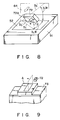
- this is a method which limits the freedom of an object 72 moving in the arrow direction in this diagram only to an elevation angle ⁇ and a rotational angle of a bar code 72a, ⁇ , with the read window 52 as a reference, and computes the number of times the bar code effectively crosses the scan lines (the number of effective scans) during a sequence of reading operations to evaluate the reading performance.
- the results of the analysis using this method are exemplified in Tables 3, 4 and 5.
- Table 3 presents the results of the analysis using the most typical, counter type bar code scanner involving five groups of scan lines, and shows that a good reading performance is secured over the entire ranges of 0° to 90° for both the rotational angle ⁇ of the bar code 72a and the elevation angle ⁇ of the object 72.
- Table 4 presents the results of the analysis in the case where the counter type bar code scanner involving five groups of scan lines as used for Table 3 is used but the reading is executed with the horizontal scan group eliminated, i.e., with four groups of scan lines, and shows deterioration of the reading performance for the rotational angle ⁇ of 20° or below.
- Table 5 shows the results of the analysis using a bar code scanner involving four groups of scan lines according to one embodiment of the present invention, with the scan line angles as indicated in Table 1 or 2. It is apparent from this table that a high reading performance is maintained over the freedom range of the object 72 and the same reading performance as provided by the scanner using five groups of scan lines can be secured by four groups of scan lines if the arrangement of the scan lines is optimized.
- test results show that the average reading times for the conventional, most typical bar code scanner using five groups of scan lines and the bar code scanner using four groups of scan lines according to the present embodiment with the scan line angles as specified by Table 1 or 2 are both approximately 0.94 sec per sample, no difference occurring in the reading performance.
- the scanner of this embodiment using four groups of scan lines can make the bar code reading apparatus significantly compact as compared with the conventional scanner using five groups of scan lines.
- the distance to the read window from the scan center is L
- the entire scan angle is ⁇ 1
- each scan line length l equals one fifth of the entire scan length as shown in Fig. 11
- This embodiment can therefore contribute to making the bar code reading apparatus significantly compact.
- the entire scan angle can be reduced from ⁇ 1 to ⁇ 2 as shown in Fig. 13. This means that the time to produce a series of scan lines can be shortened without increasing the rotational speed of the rotational scan mirror 59 shown in Fig. 4, thus permitting the number of scan lines for each group to be increased and improving the performance of reading a bar code as a consequence.
- the distance to the read window from the scan center can be made shorter than L while the entire scan angle can be made smaller than ⁇ 1 , thus ensuring both compactness of the apparatus and improvement of the bar-code reading performance at the same time.
- the reflection beam from the rotational scan mirror 59 is reflected once at the fixed scan mirrors 60-63 to provide scan beams which are to be irradiated outward through the read window 52 and four groups of scan areas instead of five are used, the number of optical components can be reduced further than the conventional compact bar code reading apparatus. This feature contributes to realizing a compacter apparatus and reducing the manufacturing cost.
- rotational scan mirror is not limited to this particular type but other prisms having three sides or five or more sides may be used as well.
- the quadratic prism may be replaced with a rotational scan mirror 74 with a polygonal pyramid shape as shown in Figs 14 and 15 with the same effect as acquired by the above-described embodiment.
- the rotational scan mirror 74 having a polygonal pyramid shape, as the mirror surfaces of the rotational scan mirror face obliquely downward, the rotational axis 74a becomes approximately parallel to the direction of a line 64 normal to the read window.
Landscapes
- Physics & Mathematics (AREA)
- Engineering & Computer Science (AREA)
- Electromagnetism (AREA)
- Health & Medical Sciences (AREA)
- General Health & Medical Sciences (AREA)
- Toxicology (AREA)
- Artificial Intelligence (AREA)
- Computer Vision & Pattern Recognition (AREA)
- General Physics & Mathematics (AREA)
- Theoretical Computer Science (AREA)
- Mechanical Optical Scanning Systems (AREA)
- Facsimile Scanning Arrangements (AREA)
Claims (4)
- Appareil de lecture de code à barres comprenant un dispositif (53) à source d'un faisceau laser, disposé dans un boîtier (51) ayant une fenêtre arrière (52) par laquelle un faisceau laser est destiné à être projeté vers l'extérieur, afin qu'un faisceau laser soit émis, et un trajet de lumière de réflexion utilisé pour le guidage d'un faisceau laser réfléchi vers la fenêtre de lecture (52), et comprenant un dispositif à miroir rotatif (59) destiné à réfléchir le faisceau laser émis par le dispositif oscillateur laser pour le balayage du faisceau laser et un dispositif à miroir fixe de balayage (60, 61, 62, 63) placé entre le dispositif à miroir rotatif (59) et la fenêtre de lecture (52) et comprenant quatre miroirs élémentaires,
caractérisé en ce que :le dispositif à miroir fixe (60 à 63) est formé par un seul miroir fixe de balayage, etles miroirs élémentaires sont disposés avec des angles déterminés entre le dispositif à miroir rotatif (59) et la fenêtre de lecture (52) afin qu'ils donnent de multiples lignes de balayage (b1-b4) dans des directions multiples dans un plan normal au plan de la fenêtre de lecture (52) à partir du faisceau laser réfléchi par le dispositif à miroir rotatif (59), les multiples lignes de balayage (b1-b4) comprenant deux groupes de lignes verticales de balayage dans le plan normal et deux groupes de lignes obliques de balayage inclinées d'un certain angle par rapport à une direction horizontale. - Appareil de lecture de code à barres selon la revendication 1, caractérisé en ce que le dispositif à miroir rotatif a une face inclinée destinée à réfléchir le faisceau laser du dispositif à source d'un faisceau laser vers le côté du boîtier qui est opposé à la fenêtre de lecture.
- Appareil de lecture de code à barres selon la revendication 1, caractérisé en ce que le dispositif à miroir rotatif a la configuration d'un prisme polygonal ayant un axe central de rotation incliné par rapport à un plan normal au plan de la fenêtre de lecture.
- Appareil de lecture de code à barres selon la revendication 1, caractérisé en ce que le dispositif à miroir rotatif a la configuration d'une pyramide polygonale dont l'axe de rotation est approximativement parallèle à un plan normal au plan de la fenêtre de lecture.
Applications Claiming Priority (4)
| Application Number | Priority Date | Filing Date | Title |
|---|---|---|---|
| JP131269/90 | 1990-05-23 | ||
| JP13126990 | 1990-05-23 | ||
| JP56789/91 | 1991-03-20 | ||
| JP3056789A JP2716278B2 (ja) | 1990-05-23 | 1991-03-20 | 定置式バーコード読取装置 |
Publications (2)
| Publication Number | Publication Date |
|---|---|
| EP0458334A1 EP0458334A1 (fr) | 1991-11-27 |
| EP0458334B1 true EP0458334B1 (fr) | 1996-12-18 |
Family
ID=26397787
Family Applications (1)
| Application Number | Title | Priority Date | Filing Date |
|---|---|---|---|
| EP91108358A Expired - Lifetime EP0458334B1 (fr) | 1990-05-23 | 1991-05-23 | Lecteur de codes à bâtonnets |
Country Status (4)
| Country | Link |
|---|---|
| EP (1) | EP0458334B1 (fr) |
| JP (1) | JP2716278B2 (fr) |
| KR (1) | KR940003827B1 (fr) |
| DE (1) | DE69123638T2 (fr) |
Cited By (3)
| Publication number | Priority date | Publication date | Assignee | Title |
|---|---|---|---|---|
| US7296748B2 (en) | 2002-01-11 | 2007-11-20 | Metrologic Instruments, Inc. | Bioptical laser scanning system providing 360° of omnidirectional bar code symbol scanning coverage at point of sale station |
| US7314176B2 (en) | 2002-01-11 | 2008-01-01 | Metrologic Instruments, Inc. | Method of generating a complex laser scanning pattern from a bioptical laser scanning system for providing 360° of omnidirectional bar code symbol scanning coverage at a point of sale station |
| US7374094B2 (en) | 2002-01-11 | 2008-05-20 | Metrologic Instruments, Inc. | Bioptical laser scanning system for providing six-sided omnidirectional bar code symbol scanning coverage at a point of sale station |
Families Citing this family (3)
| Publication number | Priority date | Publication date | Assignee | Title |
|---|---|---|---|---|
| GB9404921D0 (en) * | 1994-03-14 | 1994-04-27 | Laser scanners of high scanning frequency | |
| DE19846162C2 (de) * | 1998-10-07 | 2000-10-26 | Leuze Electronic Gmbh & Co | Optoelektronische Vorrichtung |
| JP2014098603A (ja) * | 2012-11-14 | 2014-05-29 | Toshiba Corp | 3次元モデル生成装置 |
Family Cites Families (5)
| Publication number | Priority date | Publication date | Assignee | Title |
|---|---|---|---|---|
| FR2420793A1 (fr) * | 1978-03-20 | 1979-10-19 | Sweda International Inc | Appareil d'exploration optique pour explorer et capter l'information supportee par un article portant une etiquette |
| JPS6273386A (ja) * | 1985-09-26 | 1987-04-04 | Sanden Corp | バ−コ−ド読取装置 |
| JPH0687099B2 (ja) * | 1986-10-08 | 1994-11-02 | 富士通株式会社 | レ−ザ光走査装置 |
| US4861973A (en) * | 1987-06-18 | 1989-08-29 | Spectra-Physics, Inc. | Optical scan pattern generating arrangement for a laser scanner |
| JPH0823629B2 (ja) * | 1987-08-19 | 1996-03-06 | 富士通株式会社 | 光学読取装置 |
-
1991
- 1991-03-20 JP JP3056789A patent/JP2716278B2/ja not_active Expired - Fee Related
- 1991-05-22 KR KR1019910008265A patent/KR940003827B1/ko not_active Expired - Fee Related
- 1991-05-23 DE DE69123638T patent/DE69123638T2/de not_active Expired - Fee Related
- 1991-05-23 EP EP91108358A patent/EP0458334B1/fr not_active Expired - Lifetime
Cited By (7)
| Publication number | Priority date | Publication date | Assignee | Title |
|---|---|---|---|---|
| US7341192B2 (en) | 2000-04-18 | 2008-03-11 | Metrologic Instruments, Inc. | Method of generating a complex laser scanning pattern from a bioptical laser scanning system for providing 360° of omnidirectional bar code symbol scanning coverage at a point of sale station |
| US7296748B2 (en) | 2002-01-11 | 2007-11-20 | Metrologic Instruments, Inc. | Bioptical laser scanning system providing 360° of omnidirectional bar code symbol scanning coverage at point of sale station |
| US7314176B2 (en) | 2002-01-11 | 2008-01-01 | Metrologic Instruments, Inc. | Method of generating a complex laser scanning pattern from a bioptical laser scanning system for providing 360° of omnidirectional bar code symbol scanning coverage at a point of sale station |
| US7374094B2 (en) | 2002-01-11 | 2008-05-20 | Metrologic Instruments, Inc. | Bioptical laser scanning system for providing six-sided omnidirectional bar code symbol scanning coverage at a point of sale station |
| US7422156B2 (en) | 2002-01-11 | 2008-09-09 | Metrologic Instruments, Inc. | Bioptical laser scanning system for providing six-sided 360-degree omnidirectional bar code symbol scanning coverage at a point of sale station |
| US7510118B2 (en) | 2002-01-11 | 2009-03-31 | Metrologic Instruments, Inc. | Bar code symbol scanning system employing time-division multiplexed laser scanning and signal processing to avoid optical cross-talk and other unwanted light interference |
| US7740175B2 (en) | 2002-01-11 | 2010-06-22 | Metrologic Instruments, Inc. | Point-of-sale (POS) based laser scanning system providing six-sided 360 degree omni-directional bar code symbol scanning coverage at a POS station |
Also Published As
| Publication number | Publication date |
|---|---|
| JPH04211881A (ja) | 1992-08-03 |
| KR940003827B1 (ko) | 1994-05-03 |
| DE69123638T2 (de) | 1997-04-17 |
| KR910020593A (ko) | 1991-12-20 |
| DE69123638D1 (de) | 1997-01-30 |
| JP2716278B2 (ja) | 1998-02-18 |
| EP0458334A1 (fr) | 1991-11-27 |
Similar Documents
| Publication | Publication Date | Title |
|---|---|---|
| US5286961A (en) | Bar code reader producing two groups of vertical scan lines and two groups of inclined scan lines on a plane normal to the read window | |
| EP0752680A1 (fr) | Scanner optique avec des éléments optiques avec deux surfaces pour deux rayons d'action | |
| JPH02115991A (ja) | バーコード・スキャナ | |
| US4738499A (en) | Stationary hologram scanner | |
| EP0848344B1 (fr) | Appareil de balayage d'un code optique se trouvant sur un article en mouvement et méthode de balayage d'un tel code optique par moyen d'un tel appareil de balayage | |
| KR100444814B1 (ko) | 광주사장치및방법과광원모듈 | |
| US5340982A (en) | Symbol reading device for varying the focal point of a scanning laser beam through variance of scanning laser beam optical path length | |
| US5298729A (en) | Multiple depth of field optical scanner | |
| EP0458334A1 (fr) | Lecteur de codes à bâtonnets | |
| KR100335624B1 (ko) | 레이저빔주사장치 | |
| JPS6448017A (en) | Optical reader | |
| US4565421A (en) | Plural-beam scanning apparatus | |
| JPH07200714A (ja) | 光学記号読取装置 | |
| JPS5915216A (ja) | 光走査装置 | |
| JPH01321582A (ja) | バーコード読取装置 | |
| JP2788317B2 (ja) | バーコードリーダにおける走査パターンの形成装置 | |
| KR100310132B1 (ko) | 2차원 레이저 스캐닝 시스템 | |
| JP2761051B2 (ja) | 情報読取装置 | |
| JP2825108B2 (ja) | バーコード情報読取り装置 | |
| JP2729729B2 (ja) | ラスタースキャン方式バーコードリーダ | |
| JPH02101595A (ja) | バーコードスキヤナ | |
| JPH07250209A (ja) | 半導体レーザアレイを用いた光記録装置 | |
| JPH03249724A (ja) | レーザバーコードスキャナ | |
| JPH05182000A (ja) | バーコードリーダの走査パターン発生装置 | |
| JPH04142683A (ja) | 光学記号読取装置 |
Legal Events
| Date | Code | Title | Description |
|---|---|---|---|
| PUAI | Public reference made under article 153(3) epc to a published international application that has entered the european phase |
Free format text: ORIGINAL CODE: 0009012 |
|
| 17P | Request for examination filed |
Effective date: 19910523 |
|
| AK | Designated contracting states |
Kind code of ref document: A1 Designated state(s): DE FR GB IT NL |
|
| 17Q | First examination report despatched |
Effective date: 19950124 |
|
| RAP1 | Party data changed (applicant data changed or rights of an application transferred) |
Owner name: KABUSHIKI KAISHA TEC |
|
| GRAG | Despatch of communication of intention to grant |
Free format text: ORIGINAL CODE: EPIDOS AGRA |
|
| GRAH | Despatch of communication of intention to grant a patent |
Free format text: ORIGINAL CODE: EPIDOS IGRA |
|
| GRAH | Despatch of communication of intention to grant a patent |
Free format text: ORIGINAL CODE: EPIDOS IGRA |
|
| GRAA | (expected) grant |
Free format text: ORIGINAL CODE: 0009210 |
|
| AK | Designated contracting states |
Kind code of ref document: B1 Designated state(s): DE FR GB IT NL |
|
| ITF | It: translation for a ep patent filed | ||
| REF | Corresponds to: |
Ref document number: 69123638 Country of ref document: DE Date of ref document: 19970130 |
|
| ET | Fr: translation filed | ||
| PLBE | No opposition filed within time limit |
Free format text: ORIGINAL CODE: 0009261 |
|
| STAA | Information on the status of an ep patent application or granted ep patent |
Free format text: STATUS: NO OPPOSITION FILED WITHIN TIME LIMIT |
|
| 26N | No opposition filed | ||
| PGFP | Annual fee paid to national office [announced via postgrant information from national office to epo] |
Ref country code: DE Payment date: 20010514 Year of fee payment: 11 |
|
| PGFP | Annual fee paid to national office [announced via postgrant information from national office to epo] |
Ref country code: FR Payment date: 20010518 Year of fee payment: 11 |
|
| PGFP | Annual fee paid to national office [announced via postgrant information from national office to epo] |
Ref country code: GB Payment date: 20010523 Year of fee payment: 11 |
|
| PGFP | Annual fee paid to national office [announced via postgrant information from national office to epo] |
Ref country code: NL Payment date: 20010531 Year of fee payment: 11 |
|
| REG | Reference to a national code |
Ref country code: GB Ref legal event code: IF02 |
|
| PG25 | Lapsed in a contracting state [announced via postgrant information from national office to epo] |
Ref country code: GB Free format text: LAPSE BECAUSE OF NON-PAYMENT OF DUE FEES Effective date: 20020523 |
|
| PG25 | Lapsed in a contracting state [announced via postgrant information from national office to epo] |
Ref country code: NL Free format text: LAPSE BECAUSE OF NON-PAYMENT OF DUE FEES Effective date: 20021201 |
|
| PG25 | Lapsed in a contracting state [announced via postgrant information from national office to epo] |
Ref country code: DE Free format text: LAPSE BECAUSE OF NON-PAYMENT OF DUE FEES Effective date: 20021203 |
|
| GBPC | Gb: european patent ceased through non-payment of renewal fee |
Effective date: 20020523 |
|
| PG25 | Lapsed in a contracting state [announced via postgrant information from national office to epo] |
Ref country code: FR Free format text: LAPSE BECAUSE OF NON-PAYMENT OF DUE FEES Effective date: 20030131 |
|
| NLV4 | Nl: lapsed or anulled due to non-payment of the annual fee |
Effective date: 20021201 |
|
| REG | Reference to a national code |
Ref country code: FR Ref legal event code: ST |
|
| PG25 | Lapsed in a contracting state [announced via postgrant information from national office to epo] |
Ref country code: IT Free format text: LAPSE BECAUSE OF NON-PAYMENT OF DUE FEES;WARNING: LAPSES OF ITALIAN PATENTS WITH EFFECTIVE DATE BEFORE 2007 MAY HAVE OCCURRED AT ANY TIME BEFORE 2007. THE CORRECT EFFECTIVE DATE MAY BE DIFFERENT FROM THE ONE RECORDED. Effective date: 20050523 |