EP0458401B1 - Schwimmventil mit Niveauregelung durch Gestell, insbesondere für Wasserbehälter von Sanitäranlagen - Google Patents
Schwimmventil mit Niveauregelung durch Gestell, insbesondere für Wasserbehälter von Sanitäranlagen Download PDFInfo
- Publication number
- EP0458401B1 EP0458401B1 EP19910201182 EP91201182A EP0458401B1 EP 0458401 B1 EP0458401 B1 EP 0458401B1 EP 19910201182 EP19910201182 EP 19910201182 EP 91201182 A EP91201182 A EP 91201182A EP 0458401 B1 EP0458401 B1 EP 0458401B1
- Authority
- EP
- European Patent Office
- Prior art keywords
- chamber
- float
- pipe
- valve
- closure member
- Prior art date
- Legal status (The legal status is an assumption and is not a legal conclusion. Google has not performed a legal analysis and makes no representation as to the accuracy of the status listed.)
- Expired - Lifetime
Links
- XLYOFNOQVPJJNP-UHFFFAOYSA-N water Substances O XLYOFNOQVPJJNP-UHFFFAOYSA-N 0.000 title claims description 25
- 230000000903 blocking effect Effects 0.000 claims description 4
- 238000004891 communication Methods 0.000 claims description 2
- 230000005540 biological transmission Effects 0.000 claims 3
- 230000008878 coupling Effects 0.000 claims 2
- 238000010168 coupling process Methods 0.000 claims 2
- 238000005859 coupling reaction Methods 0.000 claims 2
- 230000002441 reversible effect Effects 0.000 claims 2
- 230000009347 mechanical transmission Effects 0.000 claims 1
- 238000007789 sealing Methods 0.000 description 6
- 238000011010 flushing procedure Methods 0.000 description 4
- 238000010276 construction Methods 0.000 description 2
- 229910001369 Brass Inorganic materials 0.000 description 1
- 238000005452 bending Methods 0.000 description 1
- 239000010951 brass Substances 0.000 description 1
- 230000001419 dependent effect Effects 0.000 description 1
- 238000006073 displacement reaction Methods 0.000 description 1
- 230000000694 effects Effects 0.000 description 1
- 239000013536 elastomeric material Substances 0.000 description 1
- 238000007667 floating Methods 0.000 description 1
- 210000004907 gland Anatomy 0.000 description 1
- 239000012535 impurity Substances 0.000 description 1
- 238000009434 installation Methods 0.000 description 1
- 238000004519 manufacturing process Methods 0.000 description 1
- 239000002184 metal Substances 0.000 description 1
- 239000007769 metal material Substances 0.000 description 1
- 238000005192 partition Methods 0.000 description 1
Images

Classifications
-
- F—MECHANICAL ENGINEERING; LIGHTING; HEATING; WEAPONS; BLASTING
- F16—ENGINEERING ELEMENTS AND UNITS; GENERAL MEASURES FOR PRODUCING AND MAINTAINING EFFECTIVE FUNCTIONING OF MACHINES OR INSTALLATIONS; THERMAL INSULATION IN GENERAL
- F16K—VALVES; TAPS; COCKS; ACTUATING-FLOATS; DEVICES FOR VENTING OR AERATING
- F16K31/00—Actuating devices; Operating means; Releasing devices
- F16K31/12—Actuating devices; Operating means; Releasing devices actuated by fluid
- F16K31/18—Actuating devices; Operating means; Releasing devices actuated by fluid actuated by a float
- F16K31/20—Actuating devices; Operating means; Releasing devices actuated by fluid actuated by a float actuating a lift valve
- F16K31/24—Actuating devices; Operating means; Releasing devices actuated by fluid actuated by a float actuating a lift valve with a transmission with parts linked together from a single float to a single valve
- F16K31/26—Actuating devices; Operating means; Releasing devices actuated by fluid actuated by a float actuating a lift valve with a transmission with parts linked together from a single float to a single valve with the valve guided for rectilinear movement and the float attached to a pivoted arm
- F16K31/265—Actuating devices; Operating means; Releasing devices actuated by fluid actuated by a float actuating a lift valve with a transmission with parts linked together from a single float to a single valve with the valve guided for rectilinear movement and the float attached to a pivoted arm with a second lever or toggle between the pivoted arm and the valve
-
- E—FIXED CONSTRUCTIONS
- E03—WATER SUPPLY; SEWERAGE
- E03D—WATER-CLOSETS OR URINALS WITH FLUSHING DEVICES; FLUSHING VALVES THEREFOR
- E03D1/00—Water flushing devices with cisterns ; Setting up a range of flushing devices or water-closets; Combinations of several flushing devices
- E03D1/30—Valves for high or low level cisterns; Their arrangement ; Flushing mechanisms in the cistern, optionally with provisions for a pre-or a post- flushing and for cutting off the flushing mechanism in case of leakage
- E03D1/33—Adaptations or arrangements of floats
Definitions
- the subject of the present invention is a float valve for controlling the filling level of water storage cisterns for the flushing of sanitary systems, equipped with a filling level adjustment device of limited size.
- cisterns which may be of the external type or of the reduced thickness type for housing within a partition wall, takes place by means of a float valve, adapted for closing the inlet opening for the water when the water surface in the cistern reaches the desired level.
- the known float valves are usually composed of a valve, the body of which is connected to the inlet pipe for water into the cistern, and equipped with a movable closure member which closes the opening under the thrust action of a rod, at the free end of which a float is mounted; the position at which the valve comes into action can thus be selected by bending said rod until it becomes immersed by a sufficient amount to create the thrust necessary, with the lever ratios present, for closing the closure member of the valve against its seating.
- Valves of this type are especially noisy: in fact, when the cistern is empty or only partly filled, the water falls into the cistern from a mounting position for the valve located near the upper edge of said cistern, producing the typical gurgling noise; a further disadvantage of the floats of the conventional type with a rod results from the appreciable overall size in the longitudinal direction of the rod and of the float mounted at its end, which in some cases can interfere with the discharge valve for the cistern.
- Valves are also known, for example from Utility Model IT-209,417, which possess an auxiliary chamber, in which the float is positioned, these valves being adapted for reducing the volume to be filled for the purpose of obtaining the necessary increase in level for closing the valve; such valves exhibit, however, difficult adjustment of the water level in the cistern, because it is necessary, in order to make this adjustment, to adjust auxiliary means fitted to one of the sides of the chamber, the displacement of which means varies the entry level of the water into said chamber, in this way fixing the instant at which the closure of the feed opening comes into effect.
- the valve must also be capable of being fitted to already existing storage cisterns which have not been expressly designed for receiving it, and shall be easy and economical to manufacture and maintain.
- the valve according to this invention is composed basically of an inlet body 1, formed of an inlet pipe 1a having a horizontal axis and integral with a tubular connector 1b having a vertical axis, disposed laterally of the inlet pipe 1a and brought into communication with it via an opening 1c.
- Said tubular connector 1b is fitted to a length of down-pipe 2, equipped with a reference set of teeth 2a formed on a sector of the external surface of same, a chamber 3 being associated with said length of pipe 2 by a sleeve 3a integral with this chamber.
- connection between sleeve 3a and pipe 2 is made reversibly fixed by means of a tongue 4, equipped with a small tooth 4a, which engages into the gaps of the set of teeth 2a of the pipe 2, thus fixing the position of the chamber relative to the valve 1.
- a tongue 4 equipped with a small tooth 4a, which engages into the gaps of the set of teeth 2a of the pipe 2, thus fixing the position of the chamber relative to the valve 1.
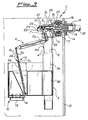
- a float 40 Inside the chamber 3 is housed a float 40, connected by means of a connecting rod of adjustable length 5, a first lever 6 and a second-lever 7, to the closure member 8, which can be seen in Fig. 3, housed inside the inlet pipe 1a of the body 1.
- the adjustable connecting rod 5 is composed of a slider 5a, slidable inside a guide element 5b, the fixing of which in position is assured by the engagement of a small tooth 5c of an end tongue 5d of the guide 5b with pairs of notches 5e disposed at various heights along the slider 5a.
- the chamber 3 is also provided with a bottom valve 12, having a floating movable closure member 13, for example of the open-bottomed bell type, forming a seal, when thrust upwards, against a rim seating 14.
- the inlet body 1 possesses a threaded connector 15, suitably of metallic material, usually brass, according to the specifications of existing standards, connected by means of a threaded tightening collar 16 to the inlet pipe 1a; the collar 16 also blocks, inside the inlet pipe 1a, the sealing seating 17, having an inlet duct of small cross-section 18 and sealing surface 19, against which the insert of elastomeric material 20 of the closure member 8 acts when it is pushed onto the seating.
- a threaded connector 15 suitably of metallic material, usually brass, according to the specifications of existing standards, connected by means of a threaded tightening collar 16 to the inlet pipe 1a; the collar 16 also blocks, inside the inlet pipe 1a, the sealing seating 17, having an inlet duct of small cross-section 18 and sealing surface 19, against which the insert of elastomeric material 20 of the closure member 8 acts when it is pushed onto the seating.
- the closure member 8 is equipped with a guide rod 21, slidable in the seating 22 of the body 9 and equipped with a slot 23, into which is inserted the end 24 of the lever 7, pivotally mounted on the pipe 1a by a pin 25.
- the guide rod 21 of the closure member is slidable with clearance in its seating 22, for the purpose of allowing sealing between the rod of the closure member and its slide seating; on the rod 21, in a position adjacent to the seating for the insert 20 of the closure member, there is provided a cased gland seal 26, which forms the seal between the seating and the obturating member itself, without introducing friction in the sliding of the obturating member in the opening and closure phases of the valve.
- the float 40 connected in articulated manner to the lower end of the connecting rod 5, can slide in the chamber 3 guided along the down-pipe 2 and is appropriately composed of an open-bottomed bell, inside which there remains trapped a sufficient volume of air to ensure a buoyancy thrust adapted for creating, through the multiplication ratio provided by said lever arms, the necessary force on the closure member 8 towards the sealing seating 19 for obtaining a seal at the hydraulic pressure values of the mains, as specified by the standards in force.
- valve according to this invention is housed in a flushing cistern 31 for sanitary installations, of which one wall is indicated diagrammatically, and is connected to it by the connector 15, to which is also connected the mains water inlet pipe 32.
- the valve is therefore supported in the cistern by the connector 15 at a fixed elevation.
- the adjustment of the filling level for the cistern is achieved, in association with the characteristics of the cistern itself, by adjusting the height of the chamber 3 relative to the pipe 2 by means of the already described unblocking and blocking of the tongue 4, and also by the variation in the length of the adjustable connecting rod 5, which is effected by releasing the slider 5a and causing it to slide inside the guide 5b as far as the new position, for the purpose of keeping constant the angle of slope of the lever 7 corresponding to the opening or closing stroke of the insert 20.
- the water coming from the pipe 32 enters, via the aperture 19, into the opening 27 and flows via the aperture 1c into the tubular connector 1b and into the down-pipe 2.
- the chamber becomes partially immersed, and remains closed by the bottom valve 12, the float 13 of which is thrust upwards, as the free level of the water rises, to close the discharge opening surrounded by the sealing seating 14.
- the chamber 3 therefore remains empty, and the float 40 does not change its position, thus keeping open the inlet for the water.
- This phase occurs in a very short time because of the small volume to be filled, composed of the volume only of the chamber 3 corresponding to the rise in level of the float which actuates closure of the closure member 8.
- valve according to this invention therefore makes it possible to obtain maximum quietness in operation, to dismantle it rapidly, without any action upon the metal connections of the water mains, and lends itself to a choice in level at which the valve shall close, for the purpose of adapting it to the various cistern constructions in which it may be mounted, with simple operation for adjusting the level of the edge of the chamber without the need for further interventions or auxiliary means.
Landscapes
- Engineering & Computer Science (AREA)
- General Engineering & Computer Science (AREA)
- Mechanical Engineering (AREA)
- Health & Medical Sciences (AREA)
- Life Sciences & Earth Sciences (AREA)
- Hydrology & Water Resources (AREA)
- Public Health (AREA)
- Water Supply & Treatment (AREA)
- Float Valves (AREA)
- Control Of Non-Electrical Variables (AREA)
- Packaging Of Annular Or Rod-Shaped Articles, Wearing Apparel, Cassettes, Or The Like (AREA)
- Devices For Dispensing Beverages (AREA)
Claims (4)
- Schwimmventil mit Niveauregulierung, insbesondere für Wasserspeicherzisternen für Sanitärsysteme, zusammengesetzt aus einem Einlaßkörper (1), welcher mit der Wasserzuführeinrichtung verbunden werden kann und horizontal innerhalb einer Speicherzisterne angeordnet ist und mit einer Trageeinrichtung mit einer vertikalen Achse ausgestattet ist, und zwar mit einer Kammer (3) verbindbar, welche einen gleitfähigen Schwimmer (40) beinhaltet, welcher mittels mechanischer Übertragung und Getriebeeinrichtungen für den Auftriebdruck des Schwimmers mit einem Schließglied (8) verbunden ist, welches gleitfähig in dem Körper (1) gelagert ist und die Abdichtung gegen eine Sitzfläche (18) mit einer kleinen in dem Körper (1) angeordneten Öffnung erzeugt, wenn der Schwimmer sich in einer gehobenen Stellung befindet, wobei die Trageeinrichtung (2) außerhalb der Kammer angebracht ist und zwischen ihnen über eine Kopplungseinrichtung, eine Führungseinrichtung und eine reversible Blockiereinrichtung ein lineares relatives Gleiten bereitgestellt ist zum Zwecke einer reversiblen Einstellung des Niveaus der Kante der Kammer bezüglich zu dem Boden der Speicherzisterne, und wobei die Übertragungseinrichtung für den Auftriebdruck auf das Schließglied zum Abschließen der Wasserzufuhr zumindest ein in der Länge einstellbares Element umfaßt, zum Zweck den Hub des Schließgliedes konstant zu halten, wenn das Niveau der Kammer verändert wird, dadurch gekennzeichnet, daß die Trageeinrichtung gebildet ist aus einer mit dem Ventil einstückigen Abwärtsleitung (2), wobei die Kopplungs- und Führungseinrichtung aus der Abwärtsleitung (2) und einem Rohr (3a) gebildet sind, das mit der Kammer (3) einstückig ist, und zwar einer Ecke davon entsprechend, und welches auf der Leitung (2) gleiten kann, und daß das einstellbare Element der Übertragungseinrichtung aus einer Verbindungsstange (5) gebildet ist, welche in ihrer Länge variierbar ist und aus einem Gleiter (5a) zusammengesetzt ist, welcher an einem Übertragungshebel (6) angelenkt ist und in einer Führung (5b) gleitet, die an ihrem unteren Ende mit dem Schwimmer (40) verbunden ist.
- Schwimmventil gemäß Anspruch 1, dadurch gekennzeichnet, daß die Blockiereinrichtung bevorzugt zusammengesetzt ist aus einer Zunge (4) welche einstückig mit dem Rohr (3a) der Kammer (3) ausgebildet ist, und an ihrem freien Ende mit einem kleinen Zahn (4a) versehen ist, welcher angepaßt ist, um in die entsprechenden Sitzflächen einer Gruppe von Zähnen (2a) einzugreifen, welche auf einem Abschnitt der äußeren Fläche der Leitung (2) gebildet sind.
- Ventil gemäß Anspruch 1, dadurch gekennzeichnet, daß der Gleiter (5a) reversibel auf der Führung (5b) blockiert ist durch den Eingriff eines mit einer Endzunge (5d) der Führung (5b) einstückigen gezahnten Elementes (5c) in entsprechende auf dem Gleiter (5a) gebildete Lagerungen (5e).
- Schwimmventil für Speicherzisternen in sanitären Systemen gemäß Anspruch 1, dadurch gekennzeichnet, daß der Einlaßkörper (1) aus einer Einlaßleitung (12) zusammengesetzt ist, die eine horizontale Achse aufweist, die fest verbunden und in Strömungsverbindung ist mit einer rohrförmigen Verbinder (1b) mit einer vertikalen Achse, und seitlich bzw. quer davon angeordnet ist.
Applications Claiming Priority (2)
| Application Number | Priority Date | Filing Date | Title |
|---|---|---|---|
| IT2125990U IT219715Z2 (it) | 1990-05-25 | 1990-05-25 | Valvola a galleggiante con regolazione di livello a cremagliera particolarmente per cassette di accumulo acqua di servizi igienici |
| IT2125990U | 1990-05-25 |
Publications (2)
| Publication Number | Publication Date |
|---|---|
| EP0458401A1 EP0458401A1 (de) | 1991-11-27 |
| EP0458401B1 true EP0458401B1 (de) | 1995-05-10 |
Family
ID=11179167
Family Applications (1)
| Application Number | Title | Priority Date | Filing Date |
|---|---|---|---|
| EP19910201182 Expired - Lifetime EP0458401B1 (de) | 1990-05-25 | 1991-05-16 | Schwimmventil mit Niveauregelung durch Gestell, insbesondere für Wasserbehälter von Sanitäranlagen |
Country Status (4)
| Country | Link |
|---|---|
| EP (1) | EP0458401B1 (de) |
| DE (1) | DE69109536T2 (de) |
| ES (1) | ES2073108T3 (de) |
| IT (1) | IT219715Z2 (de) |
Families Citing this family (6)
| Publication number | Priority date | Publication date | Assignee | Title |
|---|---|---|---|---|
| DE29602227U1 (de) * | 1995-04-12 | 1996-03-28 | Geberit Technik AG, Jona, St.Gallen | Ablaufventil für einen Spülkasten |
| ITTO980247A1 (it) * | 1998-03-20 | 1999-09-20 | Oliveira & Irmao Sa | Valvola a galleggiante per l'accumulo dell'acqua in una cassetta per apparecchiature di servizi igienici. |
| GB2398620A (en) * | 2003-02-21 | 2004-08-25 | Keraflo Ltd | Adjustable float valve actuator |
| ES2544357B1 (es) * | 2014-01-28 | 2016-05-27 | Fominaya Sa | Grifo para llenado de cisternas |
| HUE061396T2 (hu) | 2019-02-18 | 2023-06-28 | Fominaya Sa | Víztartályokhoz való beömlõszelep |
| GB2631106A (en) * | 2023-06-20 | 2024-12-25 | Pengelly Rodney | A volumetric control device for a fluid volume |
Family Cites Families (5)
| Publication number | Priority date | Publication date | Assignee | Title |
|---|---|---|---|---|
| GB1285571A (en) * | 1969-02-26 | 1972-08-16 | C H Edwards Ltd | Float-controlled valves |
| FI48373C (fi) * | 1969-06-26 | 1974-09-10 | Waertsilae Oy Ab | Vesiklosetin huuhtelusäiliön täyttöventtiililaite. |
| NL7104255A (de) * | 1971-03-30 | 1972-10-03 | ||
| US4347866A (en) * | 1979-05-07 | 1982-09-07 | Hoover Universal, Inc. | Ballcock assembly |
| IT8023053V0 (it) * | 1980-10-09 | 1980-10-09 | Cibiemme Plast Spa | Rubinetto a galleggiante per cassette di lavaggio di vasi igienici, con chiusura rapida e graduazione del livello di chiusura. |
-
1990
- 1990-05-25 IT IT2125990U patent/IT219715Z2/it active IP Right Grant
-
1991
- 1991-05-16 EP EP19910201182 patent/EP0458401B1/de not_active Expired - Lifetime
- 1991-05-16 ES ES91201182T patent/ES2073108T3/es not_active Expired - Lifetime
- 1991-05-16 DE DE1991609536 patent/DE69109536T2/de not_active Expired - Fee Related
Also Published As
| Publication number | Publication date |
|---|---|
| IT219715Z2 (it) | 1993-04-28 |
| IT9021259U1 (it) | 1991-11-26 |
| EP0458401A1 (de) | 1991-11-27 |
| DE69109536T2 (de) | 1996-02-29 |
| DE69109536D1 (de) | 1995-06-14 |
| ES2073108T3 (es) | 1995-08-01 |
| IT9021259V0 (it) | 1990-05-25 |
Similar Documents
| Publication | Publication Date | Title |
|---|---|---|
| US5439025A (en) | Float operated fill valve | |
| CN107532747B (zh) | 虹吸式致动阀 | |
| US5419359A (en) | Gas and liquid backflow-preventing valve device for drains | |
| US4748699A (en) | Water closet limited flush volume control system | |
| EP0458401B1 (de) | Schwimmventil mit Niveauregelung durch Gestell, insbesondere für Wasserbehälter von Sanitäranlagen | |
| US4431024A (en) | Float-controlled valve for toilet flush tanks | |
| US4243066A (en) | Fluid flow control valves | |
| US5157796A (en) | Double flush toilet valve | |
| EP1353014B1 (de) | Schnellschliessendes Einlassventil für einen Toilettenspülkasten | |
| US4840196A (en) | Bi-stable, three condition flush tank system | |
| EP0801179A2 (de) | Gerät zur Steuerung eines Ablaufvenmtils eines Spülkastens | |
| EP3101322B1 (de) | Hahn zum befüllen von tanks | |
| US3144875A (en) | Toilet tank supply valve assembly | |
| EP0051043B1 (de) | Ventil für ein Wasserklosett | |
| US4412362A (en) | Partial flush apparatus utilizing pneumatic time delay mechanism | |
| US865300A (en) | Flush-tank. | |
| RU2052588C1 (ru) | Поплавковый клапан | |
| EP0943851B1 (de) | Schwimmerventil für die Speicherung von Wasser in einem Toilettenspülkasten | |
| US3958280A (en) | Flushing valve | |
| EP1601901B1 (de) | Füllventil für toilettenspülkasten | |
| EP3696333A1 (de) | Füllventil für zisterne | |
| GB2311360A (en) | Float operated flow control valve | |
| EP1270830A2 (de) | Zufuhrventil für einen Spülkasten | |
| CA2557956C (en) | Dual flush system for toilet | |
| SU1595043A1 (ru) | Смывное устройство с автоматическим выпуском жидкости |
Legal Events
| Date | Code | Title | Description |
|---|---|---|---|
| PUAI | Public reference made under article 153(3) epc to a published international application that has entered the european phase |
Free format text: ORIGINAL CODE: 0009012 |
|
| AK | Designated contracting states |
Kind code of ref document: A1 Designated state(s): BE DE ES FR IT LU NL |
|
| 17P | Request for examination filed |
Effective date: 19920515 |
|
| 17Q | First examination report despatched |
Effective date: 19921126 |
|
| GRAA | (expected) grant |
Free format text: ORIGINAL CODE: 0009210 |
|
| ITPR | It: changes in ownership of a european patent |
Owner name: CESSIONE EPO REG. 20;OLIVERA & IRMAO S.A. |
|
| AK | Designated contracting states |
Kind code of ref document: B1 Designated state(s): BE DE ES FR IT LU NL |
|
| REF | Corresponds to: |
Ref document number: 69109536 Country of ref document: DE Date of ref document: 19950614 |
|
| ITF | It: translation for a ep patent filed | ||
| PGFP | Annual fee paid to national office [announced via postgrant information from national office to epo] |
Ref country code: NL Payment date: 19950627 Year of fee payment: 5 |
|
| PGFP | Annual fee paid to national office [announced via postgrant information from national office to epo] |
Ref country code: ES Payment date: 19950628 Year of fee payment: 5 |
|
| PGFP | Annual fee paid to national office [announced via postgrant information from national office to epo] |
Ref country code: LU Payment date: 19950701 Year of fee payment: 5 |
|
| RAP2 | Party data changed (patent owner data changed or rights of a patent transferred) |
Owner name: OLIVEIRA & IRMAO S.A. |
|
| RIN2 | Information on inventor provided after grant (corrected) |
Free format text: CECCHI, ENZO |
|
| PGFP | Annual fee paid to national office [announced via postgrant information from national office to epo] |
Ref country code: DE Payment date: 19950726 Year of fee payment: 5 |
|
| PGFP | Annual fee paid to national office [announced via postgrant information from national office to epo] |
Ref country code: BE Payment date: 19950728 Year of fee payment: 5 |
|
| REG | Reference to a national code |
Ref country code: ES Ref legal event code: FG2A Ref document number: 2073108 Country of ref document: ES Kind code of ref document: T3 |
|
| ET | Fr: translation filed | ||
| NLT2 | Nl: modifications (of names), taken from the european patent patent bulletin |
Owner name: OLIVEIRA & IRMAO S.A. |
|
| PLBE | No opposition filed within time limit |
Free format text: ORIGINAL CODE: 0009261 |
|
| STAA | Information on the status of an ep patent application or granted ep patent |
Free format text: STATUS: NO OPPOSITION FILED WITHIN TIME LIMIT |
|
| 26N | No opposition filed | ||
| PGFP | Annual fee paid to national office [announced via postgrant information from national office to epo] |
Ref country code: FR Payment date: 19960513 Year of fee payment: 6 |
|
| PG25 | Lapsed in a contracting state [announced via postgrant information from national office to epo] |
Ref country code: LU Free format text: LAPSE BECAUSE OF NON-PAYMENT OF DUE FEES Effective date: 19960516 |
|
| PG25 | Lapsed in a contracting state [announced via postgrant information from national office to epo] |
Ref country code: ES Free format text: LAPSE BECAUSE OF NON-PAYMENT OF DUE FEES Effective date: 19960517 |
|
| PG25 | Lapsed in a contracting state [announced via postgrant information from national office to epo] |
Ref country code: BE Effective date: 19960531 |
|
| BERE | Be: lapsed |
Owner name: S.A. OLIVEIRA & IRMAO Effective date: 19960531 |
|
| PG25 | Lapsed in a contracting state [announced via postgrant information from national office to epo] |
Ref country code: NL Effective date: 19961201 |
|
| PG25 | Lapsed in a contracting state [announced via postgrant information from national office to epo] |
Ref country code: DE Effective date: 19970201 |
|
| NLV4 | Nl: lapsed or anulled due to non-payment of the annual fee |
Effective date: 19961201 |
|
| PG25 | Lapsed in a contracting state [announced via postgrant information from national office to epo] |
Ref country code: FR Free format text: LAPSE BECAUSE OF NON-PAYMENT OF DUE FEES Effective date: 19980130 |
|
| REG | Reference to a national code |
Ref country code: FR Ref legal event code: ST |
|
| REG | Reference to a national code |
Ref country code: ES Ref legal event code: FD2A Effective date: 19990405 |
|
| PG25 | Lapsed in a contracting state [announced via postgrant information from national office to epo] |
Ref country code: IT Free format text: LAPSE BECAUSE OF NON-PAYMENT OF DUE FEES Effective date: 20050516 |