EP0458575B1 - Unité de microphone stéréo - Google Patents
Unité de microphone stéréo Download PDFInfo
- Publication number
- EP0458575B1 EP0458575B1 EP91304550A EP91304550A EP0458575B1 EP 0458575 B1 EP0458575 B1 EP 0458575B1 EP 91304550 A EP91304550 A EP 91304550A EP 91304550 A EP91304550 A EP 91304550A EP 0458575 B1 EP0458575 B1 EP 0458575B1
- Authority
- EP
- European Patent Office
- Prior art keywords
- microphone unit
- stereo
- unit according
- microphone
- microphones
- Prior art date
- Legal status (The legal status is an assumption and is not a legal conclusion. Google has not performed a legal analysis and makes no representation as to the accuracy of the status listed.)
- Expired - Lifetime
Links
Images


Classifications
-
- H—ELECTRICITY
- H04—ELECTRIC COMMUNICATION TECHNIQUE
- H04R—LOUDSPEAKERS, MICROPHONES, GRAMOPHONE PICK-UPS OR LIKE ACOUSTIC ELECTROMECHANICAL TRANSDUCERS; ELECTRIC HEARING AIDS; PUBLIC ADDRESS SYSTEMS
- H04R1/00—Details of transducers, loudspeakers or microphones
- H04R1/08—Mouthpieces; Microphones; Attachments therefor
-
- H—ELECTRICITY
- H04—ELECTRIC COMMUNICATION TECHNIQUE
- H04S—STEREOPHONIC SYSTEMS
- H04S1/00—Two-channel systems
-
- H—ELECTRICITY
- H04—ELECTRIC COMMUNICATION TECHNIQUE
- H04N—PICTORIAL COMMUNICATION, e.g. TELEVISION
- H04N23/00—Cameras or camera modules comprising electronic image sensors; Control thereof
- H04N23/50—Constructional details
-
- H—ELECTRICITY
- H04—ELECTRIC COMMUNICATION TECHNIQUE
- H04R—LOUDSPEAKERS, MICROPHONES, GRAMOPHONE PICK-UPS OR LIKE ACOUSTIC ELECTROMECHANICAL TRANSDUCERS; ELECTRIC HEARING AIDS; PUBLIC ADDRESS SYSTEMS
- H04R5/00—Stereophonic arrangements
- H04R5/027—Spatial or constructional arrangements of microphones, e.g. in dummy heads
Definitions
- the present invention relates to a built-in type stereo microphone unit adapted to be installed in a video camera or the like where sound is recordable in a stereophonic mode.
- two unidirectional microphones 300 For processing input sound in a stereophonic mode, it is customary to use two unidirectional microphones 300 as illustrated in Fig. 6.
- the two microphones 300 are so disposed that the sound receiving directions thereof form an angle ⁇ (ranging from 90° to 130°) and also that the sound receiving positions thereof are spaced apart from each other by a distance greater than 15 cm.
- the unidirectional microphone 300 generally has such directional characteristic as represented by a curve P in Fig. 7, and the curve P is obtained when the microphone 300 is disposed at a center O.
- Fig. 8 also, if the microphone 300 is used in a state incorporated in a microphone capsule 300A, the characteristic shown in Fig. 7 is achieved upon mutual combination of sound waves A and B emitted from a sound source and received at the front and the back of the microphone capsule 300A.
- unidirectional microphones 300 are installed in a casing of a small-sized video camera for example, a sufficient space is not existent around microphone capsules 300A so stereophonic recordings tend to fail. Therefore it is customary that one-point stereo microphones are provided in a posture projecting outward from the casing.
- the stereo microphone unit of the present invention comprises a cabinet, two nondirectional microphones disposed with a predetermined distance therebetween on the wall of the cabinet for collecting outside sound signal, delay means for delaying each output of the microphones by a time period corresponding to the predetermined distance, and subtracter means for subtracting the output of the delay means relative to one microphone from the output of the other microphone.
- a stereophonic effect is attained with regard to relatively higher-pitched sound by the distance existent between the two microphones and, with regard to relatively higher-pitched sound, by electrically processing the audio signals inputted to and outputted from the two microphones, thereby enabling a stereophonic operation with the microphones installed in a casing of a video camera or the like.
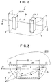
- a stereo microphone unit 1 is installed integrally with a front portion of a casing,of a video camera 200 for example.
- the stereo microphone unit 1 comprises a substantially -shaped cabinet 3 in cross section and two microphones 10, 20 housed in the cabinet 3 for left (L) and right (R) channels respectively.
- a space 3a where sound receiving surfaces c, d of the two microphones 10, 20 are positioned apart from each other by a distance lA of, e.g., 30 mm.
- the two microphones 10, 20 are nondirectional with the directivity characteristic represented by a curve Q in Fig. 9 and are disposed in such postures that the sound receiving surfaces c, d thereof are directed toward the outside of the cabinet 3. And protective net members 5, 5 are attached to the cabinet 3 at the fronts of the sound receiving surfaces c, d.
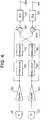
- sound waves received by the microphones 10, 20 are converted into audio signals, which are then supplied to delay circuits 50, 60 respectively via buffer amplifiers 30, 40 and are further supplied to adders 100, 90 respectively via attenuators 70, 80.
- the output signals of the attenuators 70, 80 are polarity-inverted, and the output signals of the buffer amplifiers 40, 30 are supplied also to the adders 100, 90.
- the output signals of the adders 90, 100 are supplied, as L-channel and R-channel audio signals respectively, to output terminals 130, 140 via equalizers (EQ) 110, 120 respectively.
- Each of the delay circuits 50, 60 may be composed of a general low-pass filter which principally comprises a resistor and a capacitor.
- the stereo microphone unit 1 of the constitution mentioned sound waves of any wavelengths smaller than the distance lA (in this embodiment, frequencies higher than 6 kHz) are so processed that, as will be understood from Fig. 5, level differences occur correspondingly to the distance lA among audio signals ⁇ , ⁇ , ⁇ received and outputted from the front, back and face of the microphone 10 (or 20), so that a stereophonic effect can be achieved by such frequency characteristics.
- a stereophonic sound processing operation is performed by the structure of the cabinet 3.
- This level difference is caused for what is called an acoustic shadow. That is, in Fig. 3, sound from left side of the figure, sound source A, reaches directly to the microphone 20(R). But only sound reflected from surrounding surface of the cabinets reaches to the microphone 10(L). Since the reflected sound travels a long way in the reflected path and loses energy at each reflection, the intensity of sound picked up by the microphone 10(L) is reduced.
- This acoustic shadow appears high frequency sound, more than 6 kHz, in this model. If the wave length of a sound is much longer than the distance between microphone 20(R) and 10(L), lA, in Fig. 3, acoustic shadow does not appear; but if the wave length of a sound is shorter than or as the same as the distance between two microphones the acoustic shadow appears.
- the output signal of the buffer amplifier 40 is delayed by the delay circuit 60 for such time period, and then the delayed signal is subtracted from the output signal of the buffer amplifier 30, whereby the output of the adder 90 is substantially canceled to consequently attain a stereophonic effect.
- Eq. (1) is obtained in relation to sound waves sin ⁇ t arriving at the microphone 20 (where ⁇ is angular velocity, and t is time); sound waves L ( ⁇ ) received by the microphone 10; delayed phase angle ⁇ (function of lA and ⁇ ) at the microphone 10; variation a ( ⁇ 1) in the attenuator 80; and phase angle ⁇ corresponding to the delay caused by the delay circuit.
- a stereophonic effect regarding sound waves of frequencies higher than 6 kHz can be achieved by the structure of the cabinet 3, and a stereophonic effect regarding sound waves of frequencies lower than 6 kHz can be achieved by the electric processing.
- the cabinet 3 is installed integrally with the casing of the video camera 200, a stereophonic sound receiving and recording operation can be performed in a state where the stereo microphone unit 1 is built in the casing of the video camera 200.
- a stereophonic effect with regard to relatively higher-pitched sound is attained by the structure of the cabinet, and a stereophonic effect with regard to relatively lower-pitched sound is attained by the electric constitution inclusive principally of delay circuits and adders.
Landscapes
- Engineering & Computer Science (AREA)
- Signal Processing (AREA)
- Physics & Mathematics (AREA)
- Acoustics & Sound (AREA)
- Multimedia (AREA)
- Stereophonic Arrangements (AREA)
- Circuit For Audible Band Transducer (AREA)
- Details Of Audible-Bandwidth Transducers (AREA)
Claims (8)
- Unité de microphone stéréophonique pour fournir un signal audio stéréophonique, comprenant:- un boîtier (3);- deux microphones non directionnels (10, 20) disposés avec une distance prédéterminée (1A) entre ceux-ci sur la paroi dudit boîtier (3) pour capter un signal sonore extérieur;- des moyens de retard (50, 60) pour retarder chaque signal de sortie desdits microphones d'un intervalle de temps correspondant à ladite distance prédéterminée; et- des moyens de soustraction (90, 100) pour soustraire le signal de sortie desdits moyens de retard relatifs à un microphone du signal de sortie de l'autre microphone.
- Unité de microphone stéréophonique selon la revendication 1, dans laquelle un signal audio stéréophonique n'est fourni pour ledit signal sonore extérieur que pour les fréquences inférieures à une fréquence prédéterminée.
- Unité de microphone stéréophonique selon la revendication 1 ou 2, dans laquelle les surfaces recevant le son desdits deux microphones sont dirigées vers l'extérieur, et les directions se faisant face desdits deux microphones sont opposées l'une à l'autre.
- Unité de microphone stéréophonique selon la revendication 2 ou 3, dans laquelle ladite distance prédéterminée est d'environ 30 mm et ladite fréquence prédéterminée est d'environ 6 kHz.
- Unité de microphone stéréophonique selon l'une quelconque des revendications précédentes, comprenant en outre: des moyens d'atténuation pour commander le niveau du signal de sortie desdits moyens de retard, et des moyens d'égalisation pour compenser la caractéristique de fréquence du signal de sortie desdits moyens de soustraction.
- Unité de microphone stéréophonique selon l'une quelconque des revendications précédentes, dans laquelle chaque microphone est respectivement disposé dans l'ombre acoustique de l'autre pour les sons arrivant de la gauche ou de la droite.
- Unité de microphone stéréophonique selon l'une quelconque des revendications précédentes, dans laquelle ledit circuit à retard comprend un filtre passe-bas.
- Caméra de télévision portablen comprenant:- un boîtier;- une caméra de télévision montée dans ledit boîtier et ayant une entrée pour la lumière reçue de champs d'image à analyser par ladite caméra;- une unité de microphone stéréophonique selon l'une quelconque des revendications précédentes; et- des moyens d'enregistrement pour enregistrer les signaux de sortie de ladite caméra de télévision et desdits microphones.
Applications Claiming Priority (2)
| Application Number | Priority Date | Filing Date | Title |
|---|---|---|---|
| JP132051/90 | 1990-05-22 | ||
| JP2132051A JP2946638B2 (ja) | 1990-05-22 | 1990-05-22 | 内蔵型ステレオマイクロホン |
Publications (2)
| Publication Number | Publication Date |
|---|---|
| EP0458575A1 EP0458575A1 (fr) | 1991-11-27 |
| EP0458575B1 true EP0458575B1 (fr) | 1994-08-03 |
Family
ID=15072377
Family Applications (1)
| Application Number | Title | Priority Date | Filing Date |
|---|---|---|---|
| EP91304550A Expired - Lifetime EP0458575B1 (fr) | 1990-05-22 | 1991-05-21 | Unité de microphone stéréo |
Country Status (7)
| Country | Link |
|---|---|
| US (1) | US5206910A (fr) |
| EP (1) | EP0458575B1 (fr) |
| JP (1) | JP2946638B2 (fr) |
| KR (1) | KR100240552B1 (fr) |
| AU (1) | AU634885B2 (fr) |
| CA (1) | CA2042938C (fr) |
| DE (1) | DE69103208T2 (fr) |
Families Citing this family (15)
| Publication number | Priority date | Publication date | Assignee | Title |
|---|---|---|---|---|
| JP2900722B2 (ja) * | 1992-09-30 | 1999-06-02 | 松下電器産業株式会社 | ステレオズームマイクロホン |
| DE69431356T2 (de) * | 1993-06-23 | 2003-04-17 | Apple Computer, Inc. | Computermonitor mit integriertem stereolautsprecher-richtmikrofon, und verfahren zur herstellung |
| JPH07298387A (ja) * | 1994-04-28 | 1995-11-10 | Canon Inc | ステレオ音声入力装置 |
| GB9419832D0 (en) * | 1994-10-01 | 1994-11-16 | Central Research Lab Ltd | A camera and an accessory for a camera |
| JP3547813B2 (ja) * | 1994-10-31 | 2004-07-28 | パイオニア株式会社 | 音場生成装置 |
| EP1057366A4 (fr) * | 1998-01-20 | 2007-10-17 | Roger S Keller | Appareil microphone de production de signaux pour la reproduction d'ambiance sonore |
| US6507659B1 (en) * | 1999-01-25 | 2003-01-14 | Cascade Audio, Inc. | Microphone apparatus for producing signals for surround reproduction |
| JP4277400B2 (ja) * | 1999-12-17 | 2009-06-10 | ソニー株式会社 | 音声信号記録装置 |
| PL356477A1 (en) * | 1999-12-22 | 2004-06-28 | 2+2+2 Ag | Method and arrangement for recording and playing back sounds |
| KR100542180B1 (ko) * | 2003-06-12 | 2006-01-11 | 주식회사 비에스이 | 모바일폰용 내장형 스테레오 마이크로폰의 구조 |
| JP2006295272A (ja) * | 2005-04-06 | 2006-10-26 | Sony Corp | 撮像装置 |
| JP4367484B2 (ja) | 2006-12-25 | 2009-11-18 | ソニー株式会社 | 音声信号処理装置、音声信号処理方法及び撮像装置 |
| JP5081245B2 (ja) * | 2007-08-22 | 2012-11-28 | パナソニック株式会社 | 指向性マイクロホン装置 |
| US9094496B2 (en) * | 2010-06-18 | 2015-07-28 | Avaya Inc. | System and method for stereophonic acoustic echo cancellation |
| US10440475B2 (en) | 2015-09-30 | 2019-10-08 | Sony Corporation | Signal processing device, signal processing method, and program |
Family Cites Families (8)
| Publication number | Priority date | Publication date | Assignee | Title |
|---|---|---|---|---|
| JPS5833396A (ja) * | 1981-08-20 | 1983-02-26 | Matsushita Electric Ind Co Ltd | ズ−ムマイクロホン |
| JPS58125487U (ja) * | 1982-02-19 | 1983-08-26 | セイコーインスツルメンツ株式会社 | ステレオマイク |
| JPS5964994A (ja) * | 1982-10-05 | 1984-04-13 | Matsushita Electric Ind Co Ltd | マイクロホン装置 |
| JPS5999598U (ja) * | 1982-12-23 | 1984-07-05 | キヤノン株式会社 | ステレオマイクロホンを有する撮像装置 |
| JPS6019269U (ja) * | 1983-07-15 | 1985-02-09 | オリンパス光学工業株式会社 | ビデオカメラ |
| DE3579732D1 (de) * | 1984-04-09 | 1990-10-25 | Pioneer Electronic Corp | Schallfeldverbesserungssystem. |
| JPS6022897A (ja) * | 1984-06-13 | 1985-02-05 | Matsushita Electric Ind Co Ltd | マイクロホン |
| GB2220818A (en) * | 1988-07-15 | 1990-01-17 | Gary Keith Henry | Stereo systems |
-
1990
- 1990-05-22 JP JP2132051A patent/JP2946638B2/ja not_active Expired - Lifetime
-
1991
- 1991-05-20 KR KR1019910008149A patent/KR100240552B1/ko not_active Expired - Lifetime
- 1991-05-21 CA CA002042938A patent/CA2042938C/fr not_active Expired - Lifetime
- 1991-05-21 DE DE69103208T patent/DE69103208T2/de not_active Expired - Lifetime
- 1991-05-21 US US07/703,756 patent/US5206910A/en not_active Expired - Lifetime
- 1991-05-21 AU AU77205/91A patent/AU634885B2/en not_active Expired
- 1991-05-21 EP EP91304550A patent/EP0458575B1/fr not_active Expired - Lifetime
Also Published As
| Publication number | Publication date |
|---|---|
| JPH0427298A (ja) | 1992-01-30 |
| US5206910A (en) | 1993-04-27 |
| DE69103208T2 (de) | 1995-01-12 |
| CA2042938C (fr) | 2000-03-28 |
| DE69103208D1 (de) | 1994-09-08 |
| CA2042938A1 (fr) | 1991-11-23 |
| JP2946638B2 (ja) | 1999-09-06 |
| KR910021174A (ko) | 1991-12-20 |
| AU7720591A (en) | 1991-11-28 |
| KR100240552B1 (ko) | 2000-01-15 |
| EP0458575A1 (fr) | 1991-11-27 |
| AU634885B2 (en) | 1993-03-04 |
Similar Documents
| Publication | Publication Date | Title |
|---|---|---|
| EP0458575B1 (fr) | Unité de microphone stéréo | |
| EP0509742B1 (fr) | Appareil du microphone | |
| EP0430513B1 (fr) | Appareil microphonique | |
| US5471538A (en) | Microphone apparatus | |
| US4334740A (en) | Receiving system having pre-selected directional response | |
| US4847904A (en) | Ambient imaging loudspeaker system | |
| US6731765B1 (en) | Loudspeaker device | |
| US20030016830A1 (en) | Speaker system | |
| US6031921A (en) | Loudspeaker unit | |
| JP3153912B2 (ja) | マイクロホン装置 | |
| JPH0562515B2 (fr) | ||
| JP2523951B2 (ja) | マイクロホン装置 | |
| JP2002171591A (ja) | ステレオマイクロホン装置、雑音低減処理方法及び装置 | |
| JPS5957596A (ja) | マイクロホン装置 | |
| JP3620133B2 (ja) | ステレオマイクロフォン装置 | |
| JP3146523B2 (ja) | ステレオズームマイクロホン装置 | |
| JP4853382B2 (ja) | 通話装置 | |
| JP3186909B2 (ja) | ビデオカメラ用ステレオマイクロホン | |
| JP2778710B2 (ja) | ステレオマイクロホンを用いたビデオカメラ | |
| CA1198683A (fr) | Methode et appareil pour reproduire le son avec champ ambiant et image accoustique realistes | |
| JPH05308695A (ja) | 内蔵型ステレオマイクロフォン | |
| JPS60216392A (ja) | 音響機器の音声認識装置 | |
| JPH04144399A (ja) | マイクロホン装置 | |
| JPH0247675Y2 (fr) | ||
| KR970003150Y1 (ko) | 스테레오 음향기기 |
Legal Events
| Date | Code | Title | Description |
|---|---|---|---|
| PUAI | Public reference made under article 153(3) epc to a published international application that has entered the european phase |
Free format text: ORIGINAL CODE: 0009012 |
|
| AK | Designated contracting states |
Kind code of ref document: A1 Designated state(s): DE FR GB |
|
| 17P | Request for examination filed |
Effective date: 19920502 |
|
| 17Q | First examination report despatched |
Effective date: 19931022 |
|
| GRAA | (expected) grant |
Free format text: ORIGINAL CODE: 0009210 |
|
| AK | Designated contracting states |
Kind code of ref document: B1 Designated state(s): DE FR GB |
|
| REF | Corresponds to: |
Ref document number: 69103208 Country of ref document: DE Date of ref document: 19940908 |
|
| ET | Fr: translation filed | ||
| PLBE | No opposition filed within time limit |
Free format text: ORIGINAL CODE: 0009261 |
|
| STAA | Information on the status of an ep patent application or granted ep patent |
Free format text: STATUS: NO OPPOSITION FILED WITHIN TIME LIMIT |
|
| 26N | No opposition filed | ||
| REG | Reference to a national code |
Ref country code: GB Ref legal event code: IF02 |
|
| PGFP | Annual fee paid to national office [announced via postgrant information from national office to epo] |
Ref country code: GB Payment date: 20100331 Year of fee payment: 20 |
|
| PGFP | Annual fee paid to national office [announced via postgrant information from national office to epo] |
Ref country code: FR Payment date: 20100611 Year of fee payment: 20 |
|
| PGFP | Annual fee paid to national office [announced via postgrant information from national office to epo] |
Ref country code: DE Payment date: 20100521 Year of fee payment: 20 |
|
| REG | Reference to a national code |
Ref country code: DE Ref legal event code: R071 Ref document number: 69103208 Country of ref document: DE |
|
| REG | Reference to a national code |
Ref country code: GB Ref legal event code: PE20 Expiry date: 20110520 |
|
| PG25 | Lapsed in a contracting state [announced via postgrant information from national office to epo] |
Ref country code: GB Free format text: LAPSE BECAUSE OF EXPIRATION OF PROTECTION Effective date: 20110520 |
|
| PG25 | Lapsed in a contracting state [announced via postgrant information from national office to epo] |
Ref country code: DE Free format text: LAPSE BECAUSE OF EXPIRATION OF PROTECTION Effective date: 20110522 |