EP0459353A2 - Formverfahren für Pulver aus Metall, Keramik, usw. - Google Patents
Formverfahren für Pulver aus Metall, Keramik, usw. Download PDFInfo
- Publication number
- EP0459353A2 EP0459353A2 EP91108586A EP91108586A EP0459353A2 EP 0459353 A2 EP0459353 A2 EP 0459353A2 EP 91108586 A EP91108586 A EP 91108586A EP 91108586 A EP91108586 A EP 91108586A EP 0459353 A2 EP0459353 A2 EP 0459353A2
- Authority
- EP
- European Patent Office
- Prior art keywords
- mold
- plastic mold
- powder
- cavity
- pattern
- Prior art date
- Legal status (The legal status is an assumption and is not a legal conclusion. Google has not performed a legal analysis and makes no representation as to the accuracy of the status listed.)
- Withdrawn
Links
Images
Classifications
-
- B—PERFORMING OPERATIONS; TRANSPORTING
- B22—CASTING; POWDER METALLURGY
- B22F—WORKING METALLIC POWDER; MANUFACTURE OF ARTICLES FROM METALLIC POWDER; MAKING METALLIC POWDER; APPARATUS OR DEVICES SPECIALLY ADAPTED FOR METALLIC POWDER
- B22F3/00—Manufacture of workpieces or articles from metallic powder characterised by the manner of compacting or sintering; Apparatus specially adapted therefor ; Presses and furnaces
- B22F3/02—Compacting only
- B22F3/04—Compacting only by applying fluid pressure, e.g. by cold isostatic pressing [CIP]
-
- B—PERFORMING OPERATIONS; TRANSPORTING
- B22—CASTING; POWDER METALLURGY
- B22F—WORKING METALLIC POWDER; MANUFACTURE OF ARTICLES FROM METALLIC POWDER; MAKING METALLIC POWDER; APPARATUS OR DEVICES SPECIALLY ADAPTED FOR METALLIC POWDER
- B22F3/00—Manufacture of workpieces or articles from metallic powder characterised by the manner of compacting or sintering; Apparatus specially adapted therefor ; Presses and furnaces
- B22F3/12—Both compacting and sintering
- B22F3/1208—Containers or coating used therefor
- B22F3/1258—Container manufacturing
- B22F3/1275—Container manufacturing by coating a model and eliminating the model before consolidation
Definitions
- This invention relates to a molding method capable of obtaining a molded body efficiently from the powder of a metal, ceramic or the like with rare occurrence of anisotropic contraction.
- the cold isostatic pressing is well known as the method of producing a uniform molded body by filling the powder of a metal, ceramic or the like into an elastic mold, sealing the mold and pressurizing it at ordinary temperature sing water, oil, etc. as the pressurizing medium.
- a device is necessary so as not to deform the elastic mold by the weight of the powder.
- a known method is to thicken and to strengthen the elastic mold to a certain degree.
- Japanese Patent KOKAI No. 62-297402 which comprises preparing an elastic thin mold having a prescribed form and a gas-permeable mold support having an inside form similar to the mold, and putting the mold into the mold support.
- the elastic thin mold is fitted to the inner surface of the mold support by keeping the mold support under a negative pressure, and thereby, the form of the mold is ensured.
- Raw powder is filled into the mold, degassed and then sealed. Subsequently, the mold support is detached, and the mold is subjected to the cold isostatic pressing. The mold is removed to obtain a molded body.
- the inventors already completed a method of molding the powder of a metal, ceramic, etc. which comprises forming an elastic thin mold having at least one opening on the surface of a pattern having a desired form to be molded, forming a lightly adherable mold support so as to adhrere to the outer surface of the mold, removing the pattern from the mold to form a cavity, filling a molding material powder such as metal or ceramic into the cavity through the opening, degassing, sealing, and treating the mold with cold isostatic pressing (Japanese Patent KOKAI No. 2-280999).
- the dimentional accuracy is sharply improved compared with the method of thickening and strengthening the elastic mold.
- the elastic thin mold is expanded to be fitted to the inner surface of the mold support utilizing the differential pressure, the phenomenon frequently occurred that the elastic thin mold was expanded without moving to the corresponding position of the inner surface of the mold support having a similar form.
- the above slippage caused anisotropic contraction and wrinkles. The problem became more remarkable the more the desired form became complex.
- an elastic thin mold was prepared by repeating the coating and drying of the raw rubber liquid 5 to 20 times with taking a time of 5 to 20 hours.
- An object of the invention is to provide a method of molding the powder of a metal, ceamic or the like capable of producing a molded body having a high dimentional accuracy with rare occurrence of an isotropic contraction.
- Another object of the invention is to provide a methd of molding the powder of a metal, ceramic or the like capable of producing a molded body efficiently with less labor and time.
- the present invention provides a method of molding the powder of a metal, ceramic or the like which has achieved the above objects, comprising preparing a plastic mold having at least one opening on the surface of a pattern having a desired form to be molded, removing the pattern to form a cavity on the plastic mold, filling a molding material of metal powder, ceramic powder or the like into the cavity through the opening, sealing the cavity, and treating the mold with cold isostatic pressing.
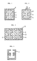
- Figures 1 to 3 are sectional views indicating a state immediately before placing in a CIP apparatus in each example of the method of the invention, respectively.
- Figure 4 is a sectional view of the mold used for preparing patterns used in the examples of the method of the invention.
- the pattern having a desired form to be molded can be taken out of the plastic mold in a form of the whole body or by breaking it
- the pattern may be composed of a material resistant to deformation which can be selected from a wide range of materials, such as metals, ceramics, plastics and woods.
- the pattern is composed of a removable or vanishable material by melting, dissolving, sublimation or the like in the range of not interfering with the function of the plastic mold.
- the materials removable by melting are wax, etc.
- the materials removable by dissolving in water or an organic solvent are polyvinyl alcohol, polyvinyl butyral, polyethylene glycol, methyl cellulose, carboxymethyl cellulose, urea, urea resin, water-soluble wax, etc.
- the materials vanishable by sublimation are naphthalene, etc.
- the powder of a metal, ceramic, plastic, wood or the like may be blended with the removable or vanishable material.
- the method of forming the above material into the pattern having a desired form may be conventional.
- a great mass may be formed into the desried form by mechanical processings, or the material may be cast into a mold having the desried form in a melted state.
- the material may be formed by injection molding in a melted or semisolidified state.
- the plastic mold is removed by melting in a later process, if there is a fear of entering the melted material into the spaces of the molded body, it is preferred to form a membrane for prevention against the entering on the surface of the pattern prior to the formation of the plastic mold.
- the plastic mold has a role of transmitting the external pressure added during cold isostatic pressing to the powder filled in the cavity of the mold, and must be composed of a material which starts plastic deformation at a pressure lower than the pressure to start the deformation of the powder layer. Otherwise, the isotropic contraction of the powder layer is not ensured, and therefore, molded bodies having a high dimentional accuracy cannot be obtained. Particularly, when the powder is composed of granules produced by granulating fine powder, the plastic mold must start plastic deformation at a low pressure of about 0.5 kg/cm2.
- the material for the plastic mold may be selected from the materials satisfying the above condition, such as waxes, e.g., beeswax, lanolin, spermaceti, montan wax, paraffin wax, microcrystalline wax, polyethylene wax, Fischer-Tropsch wax, montan wax derivatives, paraffin wax derivatives and microcrystalline wax derivatives, saturated monocarboxylic acids, e.g., lauric acid, palmitic acid, stearic acid and cerotic aicd, unsaturated carboxylic acids, e.g. fumaric acid and maleic acid, various blends containing the above materials as the principal component, oil soil, and low-melting alloys.
- waxes e.g., beeswax, lanolin, spermaceti
- montan wax paraffin wax
- microcrystalline wax polyethylene wax
- Fischer-Tropsch wax Fischer-Tropsch wax
- montan wax derivatives paraffin wax derivatives and microcrystalline wax derivatives
- the material not damaged through the removal by collapse must be selected as the material for the plastic mold.
- the plastic mold when the pattern constructed by a water-soluble material is removed by dissolving in water, the plastic mold must be formed of a material resistant to water and not softened nor melted at the applied temperature. When the pattern is removed by melting, similar limitations are required at the applied temperature.
- a means effective for preventing the plastic mold to enter the molded body is to form the plastic mold using an aggregate of swelled organic polymer particles absorbing the plastic mold material. The entering into the molded body can be prevented by rendering the particle size of the swelled particle to 50 to 5,000 ⁇ m, preferably 200 to 1,000 ⁇ m.
- a suitable swelled particle aggregate for such a plastic mold can be produced by preparing a solution composed of 80 wt. % of urea and 20 wt. % of water as the plastic mold mateial and allowing 0.5 wt. % of sodium acrylate polymer particles to absorb the solution.
- Another suitable swelled particle aggregate is produced by employing cetyl alcohol as the plastic mold material and allowing oil absorbent acrylic resin particles to absorb it.
- the plastic mold has at least one opening capable of put the powder of the molding material such as a metal or ceramic in the cavity.
- the position, size, form and the like of the opening are designed so that the powder of the molding material is filled in the form to be molded.
- the plastic mold can be prepared according to a conventional method. For example, the pattern is hung in a suitable vessel, and the aforementioned material for the plastic mold is melted and poured therein.
- the powder of the molding material such as a metal or ceramic is filled in the cavity of the plastic mold through the opening.
- the metal, ceramic and the like are moldable ones by the CIP treatment, such as stainless steels, high speed steels, tungsten carbide-cobalt mixtures, silicon carbide are titanium diboride. They may be mixed.
- a suitable particle size is 10 to 1,000 ⁇ m.
- the fine particles having a particle size of less than 10 ⁇ m are liable to agglomerate, and it is difficult to fill them in a uniform density.
- the fine particles are applicable by granulating.
- an organic binder is added in order to granulate fine powder, heretofore, 2 to 8 parts by volume of the organic binder were added to 100 parts by volume of the fine powder.
- the inventors found that the entering of the plastic mold into the molded body during the CIP treatment can be prevented by adding 10 to 100 parts by volume, preferably 20 to 80 parts by volume of the organic binder to 100 parts by volume of the fine powder.
- the organic binder prevents the entering of the plastic mold.
- the added amount is less than 20 parts by volume, particularly less than 10 parts by volume, the above effect is insufficient.
- the organic binder inhibits the consolidation of the powder.
- the organic binder paraffin wax, polyvinyl alcohol (PVA), polyvinyl butyral, carboxymethyl cellulose, polyvinyl acetate and the like are applicable.
- a metal powder having a particle size of 10 to 1,000 ⁇ m When a metal powder having a particle size of 10 to 1,000 ⁇ m is molded, it is preferable to apply a porous powder having an apparent density of 20 to 60 % of the true density, i.e. 80 to 40 % of porosity. In such a powder, particles are deformed and entangled by the consolidation to obtain a molded body having a high forming strength. As a result, even if the plastic mold enters the molded body from the surface, the surface is resistant to the occurrence of defects during demolding.
- the porous metal powder can be produced by various methods, and includes the iron powder and copper powder produced by the water atomizing method and the aluminum powder produced by the air atomizing method. Sponge titanum is also preferred.
- various additives may be added according to the desired properties or the like.
- silicon nitride alumina, yttria or the like may be added.
- a pressure transmitting vessel can be used as the sealing means.
- the pressure transmitting vessel transmits the pressure to the plastic mold placed therein without permeating the pressuring medium of water, oil or the like, and it may be an elastic vessel having a form-reversing ability or a thin bag having no form-reversing ability.
- the elastic vessel is made of natural rubber or a synthetic rubber such as styrene-butadiene rubber, polyisopropylene rubber, isobutylene rubber, isoprene rubber, silicone rubber or urethane rubber.
- the thin bag may be made of a soft plastic such as nylon, polyethylene or EVA as well as the above rubbers.
- the elastic vessel is composed of the vessel body and a lid.
- the plastic mold and the powder of the molding material are placed in the vessel body, and then the lid is attached to complete the seal.
- the plastic mold containing the powder of the molding material is put in the bag, and the opening of the bag is pinched by a jig or bound to complete the seal.
- the air in the space of the powder is removed by degassing prior to sealing, if necessary.
- sealing methods may be applicable instead of the above method using the pressure transmitting vessel. That is, after filling the powder of the molding material in the cavity of the plastic mold, the opening portion is sealed by coating a plastic material, which may be identical with or different from the material of the plastic mold, in a melted or half-melted state.
- the plastic mold may be subjected to the CIP treatment as it is, or may be sealed double by putting it in the pressure transmitting vessel.
- heating may be conducted prior to the CIP treatment.
- the plastic mold is immersed in a vessel containing a heating medium liquid, and after adjusting it to a prescribed temperature, the mold may be treated with CIP together with the vessel of the heating medium liquid.
- the CIP may be conducted using a known CIP treating apparatus.
- the treating conditions may be simular to a known method, such as pressurizing at 100 to 10,000 kg/cm2, preferably 1,000 to 5,000 kg/cm2 for 1 to 30 minutes at a maximum pressure.
- the pressurizing medium may be warmed to a temperature lower than the softening point of the plastic mold.
- the plastic mold is taken out, and the plastic mold is separated from the molded body. In the case that the plastic mold does not inhibit, the molded body may be taken out as it is. In the case that the plastic mold inhibits, the plastic mold may be broken by a mechanical means. Alternatively, the molded body may be taken out by melting the plastic mold by heating.
- the molded body is usually sintered in a conventional manner.
- the time for preparing a mold can be shortened to about 1 hour from 5 to 20 hours which is taken in the previous method.
- a silicone rubber mold prepared had a form shown in Figure 4 of which the cavity was composed of a shaft 40 mm in diameter 100 mm in length, a disc 120 mm in diameter 40 mm in thickness and an irregular shaped disc 120 mm in diameter 40-60 mm in thickness.
- a stainless steel beaker was put in a boiling water bath at 100°C, and 15 parts by weight of water and 85 parts by weight of urea were put therein and dissolved.
- the aqueous solution was poured in the mold shown in Figure 4, and naturally cooled for 1 hour. Then, the mold was detached to obtain a water-soluble pattern.
- the pattern was hung in an elastic vessel 2 made of urethane rubber shown in Figure 1.
- Paraffin wax having a melting point of 48 to 50°C was melted by heating at 60 °C. The melt was poured in the cavity, and naturally cooled to obtain a plastic mold 3. Subsequently, the elastic vessel 2 was submerged in a warm water of 40°C, and allowed to stand for 30 minutes. As a result, it was found that the pattern was entirely dissolved. After drying, the elastic vessel 2 was put on a vibrating table, and alumina granules containing 25 vol. % of PVA prepared by granulating alumina powder having a particle size of 0.7 ⁇ m were filled in the cavity of the plastic mold 3 with vibration to form a filling layer 4. Then, the elastic vessel 2 was sealed by attaching an urethane rubber lid 5.
- the elastic vessel 2 was subjected to the CIP treatment at a pressure of 5,000 kg/cm2, and then, the plastic mold containing the molded body was taken out.
- the plastic mold was heated at 60 °C by a fan dryer, the plastic mold was melted and dropped from the molded body.
- the linear contraction coefficient of the molded body thus obtained was 28.6 % to the pattern.
- the molded body was uniformly contracted, and the transferability was excellent.
- a pattern prepared in a manner similar to Example 1 was hung in a metal vessel. Paraffin wax having a melting point of 48 to 50°C was melted by heating at 60°C, and the melt was poured in the cavity followed by natural cooling to obtain a plastic mold 3. Subsequently, the plastic mold 3 taken out of the metal vessel was submerged in a warm water of 40°C, and allowed to stand for 30 minutes. As a result, it was found that the pattern was entirely dissolved. After drying, the plastic mold 3 was put on a virating table, and alumina granules containing 25 vol. % of PVA were filled in the cavity of the plastic mold 3 with vibration to form a filling layer 4.
- the plastic mold was put in a natural rubber bag, and the opening was sealed by a clamp 7 as shown in Figure 2.
- the bag 6 was subjected to the CIP treatment at a pressure of 5,000 kg/cm2, and then, the plastic mold containing the molded body was taken out.
- the plastic mold was heated at 60°C by a fan dryer, the plastic mold was melted and dropped from the molded body.
- the linear contraction coefficient of the molded body thus obtained was 28.6 % to the pattern.
- the molded body was uniformly contracted, and the transferability was excellent.
- the elastic vessel 2 was sealed by attaching an urethane rubber lid 5.
- the elastic vessel 2 was subjected to the CIP treatment at a pressure of 5,000 kg/cm2, and then, the plastic mold containing the molded bodies were taken out.
- the plastic mold was heated at 60°C by a fan dryer, the plastic mold was melted and dropped from the molded bodies.
- the linear contraction coefficients of the four molded bodies thus obtained were in the range of 28.5 to 28.7 % to the pattern.
- the molded bodies were uniformly contracted, and the transferabilities were excellent.
- a pattern prepared in a manner similar to Example 1 was hung in an elastic vessel made of urethane rubber shown in Figure 1.
- the above swelled particles were poured in the cavity followed by natural cooling to obtain a plastic mold 3.
- the elastic vessel 2 was submerged in a warm water of 40 °C, and allowed to stand for 30 minutes. As a result, it was found that the pattern was entirely dissolved.
- the elastic vessel 2 was put on a virating table, and alumina granules containing 4 vol. % of PVA were filled in the cavity of the plastic mold 3 with vibration to form a filling layer 4.
- the elastic vessel 2 was sealed by attaching an urethane rubber lid 5.
- the elastic vessel 2 was subjected to the CIP treatment at a pressure of 5,000 kg/cm2, and then, the plastic mold containing the molded body was taken out.
- the plastic mold was heated at 110°C by a fan dryer, the plastic mold was melted and dropped from the molded body.
- the linear contraction coefficient of the molded body thus obtained was 28.6 % to the pattern.
- the molded body was uniformly contracted, and the transferability was excellent.
- Alumina granules containing 4 vol. % of PVA were filled in the cavity of the plastic mold 3 prepared similar to Example 1 to form a filling layer 4. Then, the elastic vessel 2 was sealed by attaching an urethane rubber lid 5, and subjected to the CIP treatment at a pressure of 5,000 kg/cm2. The plastic mold containing the molded body was taken out, and heated at 60°C by a fan dryer. As a result, the plastic mold was melted and dropped from the molded body. However, many surface separations occurred, simultaneously, and rough surface was also observed.
- Sponge titanium powder having an apparent density of 1.1 g/cm3 and a mean particle size of 55 ⁇ m was filled in the cavity of a plastic mold prepared similar to Example 1 with vibration to form a filling layer 4. Then, the elastic vessel 2 was sealed by attaching an urethane rubber lid 5, and subjected to the CIP treatment at a pressure of 5,000 kg/cm2. The plastic mold containing the molded body was taken out, and heated at 60°C by a fan dryer. As a result, the plastic mold was melted and dropped from the molded body.
- the linear contraction coefficient of the molded body thus obtained was 35.0 % to the pattern.
- the molded body was uniformly contracted, and the transferability was excellent.
Landscapes
- Engineering & Computer Science (AREA)
- Manufacturing & Machinery (AREA)
- Mechanical Engineering (AREA)
- Physics & Mathematics (AREA)
- Fluid Mechanics (AREA)
- Powder Metallurgy (AREA)
Applications Claiming Priority (4)
| Application Number | Priority Date | Filing Date | Title |
|---|---|---|---|
| JP137107/90 | 1990-05-29 | ||
| JP13710790 | 1990-05-29 | ||
| JP288385/90 | 1990-10-29 | ||
| JP02288385A JP3099357B2 (ja) | 1990-05-29 | 1990-10-29 | 金属、セラミックス等の粉体の成形方法 |
Publications (2)
| Publication Number | Publication Date |
|---|---|
| EP0459353A2 true EP0459353A2 (de) | 1991-12-04 |
| EP0459353A3 EP0459353A3 (en) | 1993-10-27 |
Family
ID=26470527
Family Applications (1)
| Application Number | Title | Priority Date | Filing Date |
|---|---|---|---|
| EP19910108586 Withdrawn EP0459353A3 (en) | 1990-05-29 | 1991-05-27 | Molding method for powder of metal, ceramic, etc |
Country Status (1)
| Country | Link |
|---|---|
| EP (1) | EP0459353A3 (de) |
Cited By (2)
| Publication number | Priority date | Publication date | Assignee | Title |
|---|---|---|---|---|
| CN108627039A (zh) * | 2018-06-22 | 2018-10-09 | 大连海事大学 | 一种氧化铝陶瓷板式脉动热管及其制备方法 |
| US12528126B2 (en) | 2019-12-17 | 2026-01-20 | Kennametal Inc. | Additive manufacturing techniques and applications thereof |
Family Cites Families (5)
| Publication number | Priority date | Publication date | Assignee | Title |
|---|---|---|---|---|
| GB893377A (en) * | 1959-11-02 | 1962-04-11 | Gen Electric Co Ltd | Improvements in or relating to the manufacture of articles from powdered materials |
| US3230286A (en) * | 1961-01-23 | 1966-01-18 | Engelhard Ind Inc | Compacting of particulate materials |
| US3741755A (en) * | 1971-11-04 | 1973-06-26 | D Allen | Method of isostatically pressing metal powder into desired metal shapes |
| JPS507722A (de) * | 1973-05-25 | 1975-01-27 | ||
| DE3726259C1 (de) * | 1987-08-07 | 1988-12-08 | Mtu Muenchen Gmbh | Verfahren zur Herstellung von Bauteilen aus metallischem oder nichtmetallischem Pulver |
-
1991
- 1991-05-27 EP EP19910108586 patent/EP0459353A3/en not_active Withdrawn
Cited By (2)
| Publication number | Priority date | Publication date | Assignee | Title |
|---|---|---|---|---|
| CN108627039A (zh) * | 2018-06-22 | 2018-10-09 | 大连海事大学 | 一种氧化铝陶瓷板式脉动热管及其制备方法 |
| US12528126B2 (en) | 2019-12-17 | 2026-01-20 | Kennametal Inc. | Additive manufacturing techniques and applications thereof |
Also Published As
| Publication number | Publication date |
|---|---|
| EP0459353A3 (en) | 1993-10-27 |
Similar Documents
| Publication | Publication Date | Title |
|---|---|---|
| EP0356462B1 (de) | Komplexe keramische und metallische formkörper durch niederdruck-formgebung und trocknen durch sublimation | |
| JP2928486B2 (ja) | 定形体成形方法 | |
| JPH035277B2 (de) | ||
| US3769044A (en) | Compositions and methods for making molded refractory articles | |
| JPS61287702A (ja) | 粉体の成形方法 | |
| JPS61261274A (ja) | 粉体の成形方法 | |
| US3686006A (en) | Refractory cores and methods of making the same | |
| EP0403743B1 (de) | Verfahren zum Formen von Pulver | |
| EP0459353A2 (de) | Formverfahren für Pulver aus Metall, Keramik, usw. | |
| EP0647491A2 (de) | Verfahren zur Herstellung eines luftdurchlässigen Dauerforms | |
| JPH075929B2 (ja) | 粉体の鋳込み成形方法 | |
| JP3099357B2 (ja) | 金属、セラミックス等の粉体の成形方法 | |
| CA1128736A (en) | Slip-casting system | |
| US5030401A (en) | Method for molding powders | |
| EP0294806A1 (de) | Verfahren zur Herstellung eines Sinterkörpers mit hoher Dichte | |
| EP0459486A2 (de) | Modell zur Herstellung von Kokillen | |
| KR900003317B1 (ko) | 분말성형체로부터 첨가제의 제거방법 | |
| JPH02147202A (ja) | 非可塑性材料の成形方法 | |
| EP0140682A1 (de) | Verfahren zur Herstellung eines keramischen Gegenstandes | |
| EP0417765A2 (de) | Verfahren zum Herstellen einer porösen Form | |
| JPH058208A (ja) | 粉末成形体の分散媒除去方法 | |
| JPH05200711A (ja) | 粉体の成形方法 | |
| GB2200317A (en) | Isostatic moulding | |
| JPH059507A (ja) | 粉体の成形方法 | |
| JP3074004B2 (ja) | セラミックス製品の製造方法 |
Legal Events
| Date | Code | Title | Description |
|---|---|---|---|
| PUAI | Public reference made under article 153(3) epc to a published international application that has entered the european phase |
Free format text: ORIGINAL CODE: 0009012 |
|
| AK | Designated contracting states |
Kind code of ref document: A2 Designated state(s): DE FR GB SE |
|
| PUAL | Search report despatched |
Free format text: ORIGINAL CODE: 0009013 |
|
| AK | Designated contracting states |
Kind code of ref document: A3 Designated state(s): DE FR GB SE |
|
| STAA | Information on the status of an ep patent application or granted ep patent |
Free format text: STATUS: THE APPLICATION IS DEEMED TO BE WITHDRAWN |
|
| 18D | Application deemed to be withdrawn |
Effective date: 19940428 |