EP0459414A1 - Druckvergasungsvorrichtung - Google Patents
Druckvergasungsvorrichtung Download PDFInfo
- Publication number
- EP0459414A1 EP0459414A1 EP91108720A EP91108720A EP0459414A1 EP 0459414 A1 EP0459414 A1 EP 0459414A1 EP 91108720 A EP91108720 A EP 91108720A EP 91108720 A EP91108720 A EP 91108720A EP 0459414 A1 EP0459414 A1 EP 0459414A1
- Authority
- EP
- European Patent Office
- Prior art keywords
- pressure vessel
- gassification
- pressure
- water
- gas
- Prior art date
- Legal status (The legal status is an assumption and is not a legal conclusion. Google has not performed a legal analysis and makes no representation as to the accuracy of the status listed.)
- Granted
Links
- 238000005192 partition Methods 0.000 claims abstract description 27
- 238000001816 cooling Methods 0.000 claims abstract description 10
- XLYOFNOQVPJJNP-UHFFFAOYSA-N water Substances O XLYOFNOQVPJJNP-UHFFFAOYSA-N 0.000 abstract description 8
- 238000004880 explosion Methods 0.000 abstract description 4
- 238000009825 accumulation Methods 0.000 abstract description 3
- 239000007789 gas Substances 0.000 description 50
- 239000002893 slag Substances 0.000 description 6
- 230000005484 gravity Effects 0.000 description 5
- 230000008859 change Effects 0.000 description 3
- 239000011261 inert gas Substances 0.000 description 3
- 230000008901 benefit Effects 0.000 description 2
- 239000003245 coal Substances 0.000 description 2
- 230000002093 peripheral effect Effects 0.000 description 2
- 230000000191 radiation effect Effects 0.000 description 2
- 239000011819 refractory material Substances 0.000 description 2
- 238000007789 sealing Methods 0.000 description 2
- OKTJSMMVPCPJKN-UHFFFAOYSA-N Carbon Chemical compound [C] OKTJSMMVPCPJKN-UHFFFAOYSA-N 0.000 description 1
- 230000002159 abnormal effect Effects 0.000 description 1
- 229910052799 carbon Inorganic materials 0.000 description 1
- 239000000428 dust Substances 0.000 description 1
- 230000002349 favourable effect Effects 0.000 description 1
- 238000009434 installation Methods 0.000 description 1
- 239000011810 insulating material Substances 0.000 description 1
- 238000012423 maintenance Methods 0.000 description 1
- 239000000463 material Substances 0.000 description 1
- 230000007246 mechanism Effects 0.000 description 1
- 230000009467 reduction Effects 0.000 description 1
- 230000000630 rising effect Effects 0.000 description 1
Images


Classifications
-
- C—CHEMISTRY; METALLURGY
- C10—PETROLEUM, GAS OR COKE INDUSTRIES; TECHNICAL GASES CONTAINING CARBON MONOXIDE; FUELS; LUBRICANTS; PEAT
- C10J—PRODUCTION OF PRODUCER GAS, WATER-GAS, SYNTHESIS GAS FROM SOLID CARBONACEOUS MATERIAL, OR MIXTURES CONTAINING THESE GASES; CARBURETTING AIR OR OTHER GASES
- C10J3/00—Production of combustible gases containing carbon monoxide from solid carbonaceous fuels
- C10J3/72—Other features
- C10J3/86—Other features combined with waste-heat boilers
-
- C—CHEMISTRY; METALLURGY
- C10—PETROLEUM, GAS OR COKE INDUSTRIES; TECHNICAL GASES CONTAINING CARBON MONOXIDE; FUELS; LUBRICANTS; PEAT
- C10J—PRODUCTION OF PRODUCER GAS, WATER-GAS, SYNTHESIS GAS FROM SOLID CARBONACEOUS MATERIAL, OR MIXTURES CONTAINING THESE GASES; CARBURETTING AIR OR OTHER GASES
- C10J3/00—Production of combustible gases containing carbon monoxide from solid carbonaceous fuels
- C10J3/46—Gasification of granular or pulverulent flues in suspension
- C10J3/48—Apparatus; Plants
- C10J3/485—Entrained flow gasifiers
-
- C—CHEMISTRY; METALLURGY
- C10—PETROLEUM, GAS OR COKE INDUSTRIES; TECHNICAL GASES CONTAINING CARBON MONOXIDE; FUELS; LUBRICANTS; PEAT
- C10J—PRODUCTION OF PRODUCER GAS, WATER-GAS, SYNTHESIS GAS FROM SOLID CARBONACEOUS MATERIAL, OR MIXTURES CONTAINING THESE GASES; CARBURETTING AIR OR OTHER GASES
- C10J2300/00—Details of gasification processes
- C10J2300/18—Details of the gasification process, e.g. loops, autothermal operation
- C10J2300/1861—Heat exchange between at least two process streams
- C10J2300/1884—Heat exchange between at least two process streams with one stream being synthesis gas
-
- F—MECHANICAL ENGINEERING; LIGHTING; HEATING; WEAPONS; BLASTING
- F28—HEAT EXCHANGE IN GENERAL
- F28F—DETAILS OF HEAT-EXCHANGE AND HEAT-TRANSFER APPARATUS, OF GENERAL APPLICATION
- F28F2265/00—Safety or protection arrangements; Arrangements for preventing malfunction
- F28F2265/12—Safety or protection arrangements; Arrangements for preventing malfunction for preventing overpressure
Definitions
- the present invention relates to improvements in a pressurized type gassification apparatus, in which a gassification furnace main body having a water-cooled wall structure and a duct having a water-cooled wall structure and containing therein a group of gas cooling heat-exchangers for a produced gas of the gassification furnace main body are disposed.
- Fig. 4 shows one example of such apparatus having a single-wall structure, in which reference character a designates a gassification furnace main body, character b designates a water-cooled wall, character c designates a heat insulating material, character d designates a pressure vessel, and character e designates an ash hopper.
- reference character a designates a gassification furnace main body
- character b designates a water-cooled wall
- character c designates a heat insulating material
- character d designates a pressure vessel
- character e designates an ash hopper.
- a pressurized type gassification apparatus having the so-called double-wall structure in which a gassification furnace main body is disposed within a pressure vessel, was proposed (Japanese Patent Application No. 60-48202 (1985), Laid-Open Japanese Patent Specification No. 61-207492 (1986)).
- This double-wall structure is constructed of a gassification furnace main body 01 and a pressure vessel 06 containing the former therein, the inner pressure of the pressure vessel 06 is maintained at a pressure equal to or a little lower than the inner pressure of the gassification furnace main body 01, and thereby the structure is adapted to a pressure difference from the outside by dispersing the high pressure within the gassification furnace main body 01 in two steps of the structure wall of the gassification furnace main body 01 and the wall of the pressure vessel 06.
- the wall of the gassification furnace main body 01 can be made to have a thin structure, also a high thermal radiation effect can be provided by employing, for example, a water-cooled wall structure, and so, there is an advantage that a life of a gassification furnace main body can e greatly improved.
- a pressurized type gassification apparatus illustrated in Fig. 6 was proposed (Japanese Patent Application No. 60-221324 (1985), Laid-Open Japanese Patent Specification No. 62-81489 (1987)).
- this apparatus an interior of a pressure vessel 06 accommodating a gassification furnace main body 01 and an interior of a pressure vessel 013 accommodating a water-cooled wall 014 surrounding a heat-exchanger group 07 communicated with the interior of the gassification furnace main body 01 are communicated with each other through a balance pipe 016.
- a gas sealing device 018 making use of a water seal.
- a gas receiver 011 mounted to the pressure vessel 013, and between the water-cooled wall 014 and the pressure vessel 013 is formed a gas passageway 036 through which a produced gas at a low temperature can freely flow in and flow out.
- the pressure within the pressure vessel 013 can be controlled in a self-balancing manner by allowing a low-temperature produced gas at the outlet of the water-cooled wall 04 surrounding the heat-exchanger group 07 to freely flow into the pressure vessel 013, and hence a constant pressure difference can be maintained by easily following a pressure variation within the gassification furnace main body 01. Consequently, pressure control can be achieved very economically and reliably without necessitating special pressure detector means nor control means.
- a freed portion at the outlet of the water-cooled wall 014 a difference in thermal expansion between the water-cooled wall 014 and the pressure vessel 013 can be absorbed by this portion.
- the sealing device 018 making use of a water seal was provided at the slag ejection port 03 of the gassification furnace main body 01, a difference in thermal expansion between the gassification furnace main body 01 and the pressure vessel 06 also can be absorbed by this water seal structure.
- the pressurized type gassification apparatus shown in Fig. 6 and described above also could not be said to be favorable in view of a performance and use of the apparatus from the following reasons, and especially with respect to an aspect of safety there was a problem, because a low-temperature gas at the outlet of the water-cooled wall can freely flow into and flow out from the pressure vessel 013 without being subjected to any restriction.
- the gas flowed into the pressure vessel 013 fills the interior of the same vessel.
- the gas coming into contact with the water-cooled wall 014 is partly heated by heat dissipated from the inside of the water-cooled wall resulting in reduction of its specific gravity, and it rises along the water-cooled wall 014.
- a gas filling the upper portion falls due to difference in a specific gravity.
- natural convection would occur within the pressure vessel 013. Since this low-temperature gas having fallen due to natural convection passes through the gas passageway 036, mixes into a principal flow system and lowers the temperature of the produced gas, the condition of the gas fed to an apparatus in the succeeding stage becomes unstable. As this is caused by a natural convection phenomenon, it is difficult to preliminarily estimate the amount of temperature change, and it is impossible to control it.
- a pressurized type gassification apparatus in which a gassification furnace main body having a water-cooled wall structure and a duct having a water-cooled structure and containing therein a group of gas cooling heat-exchangers for a produced gas of the gassification furnace main body are disposed within a pressure vessel, improved in that an outlet of the duct and the inside of the pressure vessel are communicated with each other, a partition wall connecting the wall of the duct at a level higher than the communicated portion with an inner wall surface of the pressure vessel is provided, and also there are provided equalizing valves for communicating the respective sides of the partition wall with each other when a pressure difference between the respective sides of the partition was has become a predetermined value or larger.
- a partition wall connecting the wall of the duct having a water-cooled wall structure with an inner wall surface of a pressure vessel is provided at a level higher than a communicating portion between an outlet of the duct and the pressure vessel, normally the inside of the duct having a water-cooled water structure and the inside of the pressure vessel are shut off, and so, the above-mentioned problems caused by occurrence of natural convection within a pressure vessel can be resolved.
- a gassification furnace main body 1 is formed of a water-cooled wall structure having its inner surface covered by refractory material, and it is disposed within a pressure vessel 3 jointly with a slag hopper 2.
- a plurality of gas cooling heat-exchangers 4 are contained within a duct 9 having a water-cooled wall structure, and further, the duct 9 is disposed within a pressure vessel 5.
- These pressure vessels 3 and 5 are connected by a pressure vessel connecting pipe 7 containing a gas communication pipe 6 therein so as to form a structure for maintaining pressure balance between the respective pressure vessels.
- the gas communication pipe 6 communicates the interior of the gassification furnace main body 1 and the interior of the water-cooled wall duct 9 with each other.
- a slag ejection hopper 2 Under the gassification furnace main body 1 is disposed a slag ejection hopper 2, which is connected with the gassification furnace main body 1 via a water seal mechanism 8, so that a difference in thermal expansion caused by a temperature difference between the gassification furnace main body 1 and the pressure vessel 3 can be absorbed perfectly.
- an outlet portion of the water-cooled water duct 9 containing the gas cooling heat-exchanger group 4 therein is not directly connected with the pressure vessel 5, but is communicated with the pressure vessel 5 via a gas passageway 12 so that a low-temperature gas at the outlet of the heat-exchanger group can freely flow into and out of the pressure vessel 5.
- This gas passageway 12 is preset so as to insure a minimum gap clearance through which gas can flow at a rate necessary for maintaining balance between the pressure in the water-cooled wall duct 9 and the pressure in the pressure vessel 5.
- a partition wall 10 is provided so as to connect the water-cooled wall duct 9 containing the heat exchanger group therein with the inner wall surface of the pressure vessel 5 at a level higher than the above-mentioned gas flow passageway 12. Furthermore, this partition wall 10 is provided with equalizing valves A and B, which would open only in the case where a pressure difference between the respective sides of the partition wall has become a predetermined value or larger.
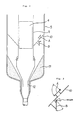
- Fig. 3 shows one example of a detailed Structure of the equalizing valves A and B mounted to the partition wall 10.
- the equalizing valve A is constructed in such manner that it may automatically open upwards against the gravity acting upon its own weight in the case where the pressure under the partition wall 10 is higher than the pressure above the partition wall 10.
- the equalizing valve B is constructed in such manner that it may automatically open against the gravity acting upon a weight mounted to a valve body in the case where the pressure above the partition wall 10 is higher than the pressure under the partition wall 10.
- the bottom portion of the space under the partition wall 10 in the pressure vessel 5 is formed in a conical shape by means of refractory material 11 for the purpose of preventing dust entered therein accompanying outflow and inflow of gas from accumulating there as much as possible.
- a high-temperature gas produced within the gassification furnace main body 1 has its sensible heat thermally recovered in the gas cooling heat-exchanger group 4, and it is fed as a low-temperature gas to a subsequent installation (not shown).
- slag would fall in the slag hopper disposed under the gassification furnace main body 1, and then it is cooled and crushed.
- the equalizing valves A and B are provided for the purpose of maintaining the pressure difference between the inside of the water-cooled wall duct 9 and the inside of the pressure vessel 5 at a certain constant balanced pressure difference which insures safety of the apparatus, and in the event that the pressure difference has exceeded this balanced pressure difference and has become an abnormal value, either one of the equalizing valves A and B would automatically open and the pressure difference would be returned to a normal value.
- equalizing valves A and B would have their appropriate specifications determined after a tolerable pressure difference has been calculated taking into consideration a structural strength and an operating condition of the pressurized type gassification apparatus.
- the equalizing valves are necessitated to be formed in such structure that a fine granular char component contained in the gas filling the inside of the pressure vessel 5 may hardly accumulate thereon.
- the equalizing valves A and B are designed under the consideration that they can aut omatically maintain the pressure within the pressure vessel at an appropriate value even upon start and stop of the pressurized type gassification apparatus and upon variation of a load, safety and reliability of the apparatus can be further improved.
- they are designed so as to operate at a pressure difference of 50 - 600 mm water column taking into account a pressure difference between the upper side and the lower side of the partition wall, an operational aperture area and an own weight of the equalizing valve and a compressive strength of the water-cooled wall duct and the pressure vessel.
- a pressurized type gassification apparatus having a double-wall structure in which a gassification furnace main body having a water-cooled wall structure and a duct having a water-cooled wall structure and containing therein a group of gas cooling heat-exchangers for a produced gas of the same gassification furnace main body are disposed within a pressure vessel, problems in the performance and utilization of the apparatus such as temperature lowering of a produced gas which occurred in the prior art as a result of natural convection of the gas within the pressure vessel and a risk of fire and explosion resulted from accumulation of char within the pressure vessel, can be resolved, and an apparatus having high safety and reliability can be provided.
Landscapes
- Chemical & Material Sciences (AREA)
- Engineering & Computer Science (AREA)
- Combustion & Propulsion (AREA)
- Oil, Petroleum & Natural Gas (AREA)
- Organic Chemistry (AREA)
- Gasification And Melting Of Waste (AREA)
- Waste-Gas Treatment And Other Accessory Devices For Furnaces (AREA)
- Fluidized-Bed Combustion And Resonant Combustion (AREA)
Applications Claiming Priority (2)
| Application Number | Priority Date | Filing Date | Title |
|---|---|---|---|
| JP2138388A JP2659849B2 (ja) | 1990-05-30 | 1990-05-30 | 加圧型ガス化装置 |
| JP138388/90 | 1990-05-30 |
Publications (2)
| Publication Number | Publication Date |
|---|---|
| EP0459414A1 true EP0459414A1 (de) | 1991-12-04 |
| EP0459414B1 EP0459414B1 (de) | 1994-12-14 |
Family
ID=15220780
Family Applications (1)
| Application Number | Title | Priority Date | Filing Date |
|---|---|---|---|
| EP91108720A Expired - Lifetime EP0459414B1 (de) | 1990-05-30 | 1991-05-28 | Druckvergasungsvorrichtung |
Country Status (4)
| Country | Link |
|---|---|
| US (1) | US5230717A (de) |
| EP (1) | EP0459414B1 (de) |
| JP (1) | JP2659849B2 (de) |
| DE (1) | DE69105820T2 (de) |
Cited By (6)
| Publication number | Priority date | Publication date | Assignee | Title |
|---|---|---|---|---|
| WO1994016037A1 (en) * | 1992-12-30 | 1994-07-21 | Combustion Engineering, Inc. | High performance coal gasifier system |
| RU2122565C1 (ru) * | 1993-03-16 | 1998-11-27 | Крупп-Копперс ГмбХ | Способ газификации под давлением высокодисперсных горючих |
| RU2122566C1 (ru) * | 1993-03-16 | 1998-11-27 | Крупп-Копперс ГмбХ | Аппарат для газификации под давлением высокодисперсных горючих |
| CN103387851A (zh) * | 2013-06-25 | 2013-11-13 | 上海鑫兴化工科技有限公司 | 废锅式气化炉 |
| US9422489B2 (en) | 2012-02-10 | 2016-08-23 | Mitsubishi Hitachi Power Systems, Ltd. | Pressure equalizing structure and pressure equalizing method for gasification furnace apparatus |
| EP2660517A3 (de) * | 2012-05-01 | 2017-12-20 | General Electric Technology GmbH | Wassersiegel an einem Rücklaufvorwärmer-Gasausgang |
Families Citing this family (14)
| Publication number | Priority date | Publication date | Assignee | Title |
|---|---|---|---|---|
| JP3017623B2 (ja) * | 1993-09-28 | 2000-03-13 | 株式会社日立製作所 | 石炭ガス化装置 |
| US5787822A (en) * | 1996-05-24 | 1998-08-04 | Emery Recycling Corporation | Oblate spheroid shaped gasification apparatus and method of gasifying a feedstock |
| US8317885B2 (en) * | 2004-11-22 | 2012-11-27 | Shell Oil Company | Apparatus for gasifying fuel with a dripper edge and heat shield |
| US7803216B2 (en) * | 2005-12-28 | 2010-09-28 | Mitsubishi Heavy Industries, Ltd. | Pressurized high-temperature gas cooler |
| US8752615B2 (en) | 2008-01-08 | 2014-06-17 | General Electric Company | Methods and systems for controlling temperature in a vessel |
| CN101475840B (zh) * | 2009-01-19 | 2012-09-05 | 张金辉 | 一种热壁煤气发生炉 |
| JP5582752B2 (ja) * | 2009-09-28 | 2014-09-03 | 三菱重工業株式会社 | ガス化炉装置、その運転方法およびこれを備えたガス化燃料発電設備 |
| US20120067551A1 (en) * | 2010-09-20 | 2012-03-22 | California Institute Of Technology | Thermal energy storage using supercritical fluids |
| KR101900118B1 (ko) * | 2011-01-14 | 2018-09-18 | 에어 프로덕츠 앤드 케미칼스, 인코오포레이티드 | 가스화 반응기 |
| WO2012101081A1 (en) * | 2011-01-25 | 2012-08-02 | Shell Internationale Research Maatschappij B.V. | Gasification reactor |
| CN103160329B (zh) * | 2013-03-22 | 2014-10-22 | 东方电气集团东方锅炉股份有限公司 | 废锅流程的水煤浆水冷壁气化炉 |
| JP5575342B1 (ja) * | 2014-02-03 | 2014-08-20 | 三菱重工業株式会社 | ガス化炉冷却構造、ガス化炉及びガス化炉のアニュラス部拡大方法 |
| CN112251258B (zh) * | 2020-11-05 | 2022-07-12 | 北京衡燃科技有限公司 | 内置双床的tfb气化炉 |
| GB202317413D0 (en) * | 2023-11-14 | 2023-12-27 | Rolls Royce Plc | Propulsion system comprising a hydrogen-burning gas turbine engine |
Citations (2)
| Publication number | Priority date | Publication date | Assignee | Title |
|---|---|---|---|---|
| US2862480A (en) * | 1954-09-10 | 1958-12-02 | Babcock & Wilcox Co | Synthesis gas reactor and heat exchanger |
| EP0094097A2 (de) * | 1982-05-11 | 1983-11-16 | KRW Energy Systems Inc. | Nicht verstopfende Rohrenplatte mit Druckausgleichsystem für Kohlevergasungswärmetauscher |
Family Cites Families (11)
| Publication number | Priority date | Publication date | Assignee | Title |
|---|---|---|---|---|
| US4610697A (en) * | 1984-12-19 | 1986-09-09 | Combustion Engineering, Inc. | Coal gasification system with product gas recycle to pressure containment chamber |
| JPS62257985A (ja) * | 1986-05-02 | 1987-11-10 | Mitsubishi Heavy Ind Ltd | 微粉炭スラリフイ−ド空気吹きガス化装置 |
| JPH0637623B2 (ja) * | 1986-09-30 | 1994-05-18 | 三菱重工業株式会社 | 石炭ガス化装置 |
| JPS649290A (en) * | 1987-07-01 | 1989-01-12 | Mitsubishi Heavy Ind Ltd | Fire protection device in pressure vessel of coal gasifier oven |
| JPH01228092A (ja) * | 1988-03-09 | 1989-09-12 | Takamisawa Cybernetics Co Ltd | 宅配便無人受付装置 |
| JPH01238886A (ja) * | 1988-03-18 | 1989-09-25 | Masaru Nagai | 棋譜入力方式と棋譜記録媒体 |
| JPH01250094A (ja) * | 1988-03-30 | 1989-10-05 | Nuclear Fuel Ind Ltd | 核燃料棒 |
| DE3824233A1 (de) * | 1988-07-16 | 1990-01-18 | Krupp Koppers Gmbh | Anlage fuer die erzeugung eines produktgases aus einem feinteiligen kohlenstofftraeger |
| JPH0281489A (ja) * | 1988-09-16 | 1990-03-22 | Victor Co Of Japan Ltd | 磁電変換素子 |
| JPH0386796A (ja) * | 1989-08-31 | 1991-04-11 | Tonen Corp | 空気圧縮機用潤滑油組成物 |
| JPH0386795A (ja) * | 1989-08-31 | 1991-04-11 | Tonen Corp | 水分離性に優れた潤滑油組成物 |
-
1990
- 1990-05-30 JP JP2138388A patent/JP2659849B2/ja not_active Expired - Lifetime
-
1991
- 1991-05-28 EP EP91108720A patent/EP0459414B1/de not_active Expired - Lifetime
- 1991-05-28 DE DE69105820T patent/DE69105820T2/de not_active Expired - Fee Related
- 1991-05-29 US US07/707,001 patent/US5230717A/en not_active Expired - Fee Related
Patent Citations (2)
| Publication number | Priority date | Publication date | Assignee | Title |
|---|---|---|---|---|
| US2862480A (en) * | 1954-09-10 | 1958-12-02 | Babcock & Wilcox Co | Synthesis gas reactor and heat exchanger |
| EP0094097A2 (de) * | 1982-05-11 | 1983-11-16 | KRW Energy Systems Inc. | Nicht verstopfende Rohrenplatte mit Druckausgleichsystem für Kohlevergasungswärmetauscher |
Non-Patent Citations (1)
| Title |
|---|
| PATENT ABSTRACTS OF JAPAN vol. 12, no. 316 (C-524)(3163) August 26, 1988 & JP-A-63 86 796 (MITSUBISHI HEAVY IND. ) April 18, 1988 * |
Cited By (7)
| Publication number | Priority date | Publication date | Assignee | Title |
|---|---|---|---|---|
| WO1994016037A1 (en) * | 1992-12-30 | 1994-07-21 | Combustion Engineering, Inc. | High performance coal gasifier system |
| RU2122565C1 (ru) * | 1993-03-16 | 1998-11-27 | Крупп-Копперс ГмбХ | Способ газификации под давлением высокодисперсных горючих |
| RU2122566C1 (ru) * | 1993-03-16 | 1998-11-27 | Крупп-Копперс ГмбХ | Аппарат для газификации под давлением высокодисперсных горючих |
| US9422489B2 (en) | 2012-02-10 | 2016-08-23 | Mitsubishi Hitachi Power Systems, Ltd. | Pressure equalizing structure and pressure equalizing method for gasification furnace apparatus |
| EP2660517A3 (de) * | 2012-05-01 | 2017-12-20 | General Electric Technology GmbH | Wassersiegel an einem Rücklaufvorwärmer-Gasausgang |
| CN103387851A (zh) * | 2013-06-25 | 2013-11-13 | 上海鑫兴化工科技有限公司 | 废锅式气化炉 |
| CN103387851B (zh) * | 2013-06-25 | 2015-12-23 | 上海尧兴投资管理有限公司 | 废锅式气化炉 |
Also Published As
| Publication number | Publication date |
|---|---|
| JP2659849B2 (ja) | 1997-09-30 |
| DE69105820T2 (de) | 1995-05-18 |
| EP0459414B1 (de) | 1994-12-14 |
| DE69105820D1 (de) | 1995-01-26 |
| JPH0433993A (ja) | 1992-02-05 |
| US5230717A (en) | 1993-07-27 |
Similar Documents
| Publication | Publication Date | Title |
|---|---|---|
| EP0459414B1 (de) | Druckvergasungsvorrichtung | |
| EP1847773B1 (de) | Integrierter wirbelschichtaschenkühler | |
| US5060599A (en) | Method and reactor for combustion in a fluidized bed | |
| US5233943A (en) | Synthetic gas radiant cooler with internal quenching and purging facilities | |
| JP2005195573A (ja) | 液体金属炉の安定的な受動残熱除去系 | |
| US4614167A (en) | Combustion chamber having beds located one above the other and a method of controlling it | |
| EP0234265B1 (de) | Verfahren und Vorrichtung zum Regeln einer Druck-Wirbelbett-Brennkammer in einer Kraftwerksanlage | |
| US4588548A (en) | Pressurizer passive steam relief and quench spray system | |
| US4061317A (en) | Blast furnace bottom cooling arrangement | |
| US5499498A (en) | Pressurized fluidized bed reactor | |
| JPH0117044B2 (de) | ||
| JPH0560515B2 (de) | ||
| CN101311626A (zh) | 整体式流化床灰冷却器 | |
| JPS61218692A (ja) | 石炭ガス化装置 | |
| JPH0637623B2 (ja) | 石炭ガス化装置 | |
| JPS6386796A (ja) | 石炭ガス化装置 | |
| JP2746831B2 (ja) | 加圧式石炭ガス化装置のシール機構 | |
| JP2851409B2 (ja) | 液体金属冷却高速増殖炉の炉構造 | |
| JPH0374492A (ja) | 加圧型ガス化装置 | |
| JPH0754280Y2 (ja) | 石炭ガス化炉のボイラ壁保護装置 | |
| CN117844501A (zh) | 一种干熄焦副省煤器的保护装置 | |
| CA1155662A (en) | Combination with a gasification generator | |
| JPH046497A (ja) | 加圧水型原子炉 | |
| JPH0518577Y2 (de) | ||
| JPS6066194A (ja) | 制御棒駆動装置の冷却水供給装置及び制御棒駆動装置の冷却方法 |
Legal Events
| Date | Code | Title | Description |
|---|---|---|---|
| PUAI | Public reference made under article 153(3) epc to a published international application that has entered the european phase |
Free format text: ORIGINAL CODE: 0009012 |
|
| 17P | Request for examination filed |
Effective date: 19910625 |
|
| AK | Designated contracting states |
Kind code of ref document: A1 Designated state(s): DE NL |
|
| 17Q | First examination report despatched |
Effective date: 19920731 |
|
| GRAA | (expected) grant |
Free format text: ORIGINAL CODE: 0009210 |
|
| AK | Designated contracting states |
Kind code of ref document: B1 Designated state(s): DE NL |
|
| REF | Corresponds to: |
Ref document number: 69105820 Country of ref document: DE Date of ref document: 19950126 |
|
| PLBE | No opposition filed within time limit |
Free format text: ORIGINAL CODE: 0009261 |
|
| STAA | Information on the status of an ep patent application or granted ep patent |
Free format text: STATUS: NO OPPOSITION FILED WITHIN TIME LIMIT |
|
| 26N | No opposition filed | ||
| PGFP | Annual fee paid to national office [announced via postgrant information from national office to epo] |
Ref country code: NL Payment date: 20030530 Year of fee payment: 13 |
|
| PGFP | Annual fee paid to national office [announced via postgrant information from national office to epo] |
Ref country code: DE Payment date: 20030605 Year of fee payment: 13 |
|
| PG25 | Lapsed in a contracting state [announced via postgrant information from national office to epo] |
Ref country code: NL Free format text: LAPSE BECAUSE OF NON-PAYMENT OF DUE FEES Effective date: 20041201 Ref country code: DE Free format text: LAPSE BECAUSE OF NON-PAYMENT OF DUE FEES Effective date: 20041201 |
|
| NLV4 | Nl: lapsed or anulled due to non-payment of the annual fee |
Effective date: 20041201 |