EP0459640A1 - Dispositif de fermeture d'enveloppe - Google Patents
Dispositif de fermeture d'enveloppe Download PDFInfo
- Publication number
- EP0459640A1 EP0459640A1 EP91304172A EP91304172A EP0459640A1 EP 0459640 A1 EP0459640 A1 EP 0459640A1 EP 91304172 A EP91304172 A EP 91304172A EP 91304172 A EP91304172 A EP 91304172A EP 0459640 A1 EP0459640 A1 EP 0459640A1
- Authority
- EP
- European Patent Office
- Prior art keywords
- envelopes
- envelope
- nip
- area
- revolving drum
- Prior art date
- Legal status (The legal status is an assumption and is not a legal conclusion. Google has not performed a legal analysis and makes no representation as to the accuracy of the status listed.)
- Withdrawn
Links
Images


Classifications
-
- B—PERFORMING OPERATIONS; TRANSPORTING
- B43—WRITING OR DRAWING IMPLEMENTS; BUREAU ACCESSORIES
- B43M—BUREAU ACCESSORIES NOT OTHERWISE PROVIDED FOR
- B43M5/00—Devices for closing envelopes
- B43M5/04—Devices for closing envelopes automatic
- B43M5/042—Devices for closing envelopes automatic for envelopes with only one flap
-
- B—PERFORMING OPERATIONS; TRANSPORTING
- B43—WRITING OR DRAWING IMPLEMENTS; BUREAU ACCESSORIES
- B43M—BUREAU ACCESSORIES NOT OTHERWISE PROVIDED FOR
- B43M5/00—Devices for closing envelopes
- B43M5/04—Devices for closing envelopes automatic
- B43M5/047—Devices for closing envelopes automatic using pressure-sensitive adhesive
Definitions
- This invention relates to apparatus for automatic sealing of envelopes for example as employed in equipment for automatic insertion of inserts into envelopes in preparation of mass-mailable articles, and more particularly to high-speed apparatus for sealing of gummed envelope flaps.
- Envelopes have been sealed in the past in different ways in a variety of mechanisms, most of which rely upon moving envelopes through a line nip between rollers, between a roller and a moving belt, or between a roller and a stationary resilient member.
- Such prior art sealers impart sealing pressure only briefly and substantially only along a sweeping contact line that is transversely oriented to the conveying motion of the envelope. Once the line nip has passed over a location on an envelope, the sealing pressure is relieved at that location and resilient properties of the envelope material and the contents thereof tend to again open the flap.
- the adhesive may not have had adequate time to dry and harden for permanent adhesion.
- an insert-containing envelope bulges and, therefore, generally does not present flat parallel surfaces to a line nip. Consequently, sealing pressure is not generally applied evenly or continuously along the line nip. As a result, sealing achieved in this manner is often irregular, unreliable, and subject to failure.
- flaps are not always reliably and completely sealed and can reopen.
- the reliability of sealing is of utmost importance and sealing failures, even if occurring only occasionally, are highly undesirable and can have serious detrimerital effects not only in further machine-processing of the envelopes, but also for example in subsequent mail handling.
- U.S. Patent No. 820,427 One prior art envelope sealing device relying upon a line nip between a pair of revolving rollers to seal envelopes passed therethrough is disclosed by Markoe in U.S. Patent No. 820,427.
- Other sealing devices relying upon a line nip between a roller and an endless belt are shown in U.S. Patent Nos.705,531 (Jones) and 3,878,025 (Storace).
- U.S. Patent No. 1,632,648 issued to Gray includes a sealing device that seals a moistened envelope flap onto an envelope body as the envelope passes beneath a pressure spring 30 (FIGS.2-3).
- the envelope sealer device of the present invention particularly obviates incidences of unreliable, inadequate or incomplete sealing, seal failure, and flap reopening which can occur especially in high-speed and high-quantity handling of envelopes. Such undesirable incidences can be particularly encountered in high-rate envelope handling when sealing mechanisms of the kind taught in prior art are utilized, which sealing mechanisms rely only on brief application of sealing pressure to locations along a line nip while an envelope is passed therethrough.
- An important overall feature of the invention is the provision of an improved-reliability envelope flap sealing mechanism for use in high-rate envelope handling, wherein the sealing mechanism includes an area nip formed between an elastic resilient belt and a drum surface so that the area nip can appropriately adapt and conform to a bulging non-flat envelope, and whereby substantially each location of the envelope flap is exposed to sealing pressure for an extended time as the envelope passes through the area nip.
- an envelope sealer for high-rate sealing is fed in seriatim with other envelopes.
- the envelope sealer comprises a revolving drum and a moving, endless, resilient elastic belt that encircles a portion of the drum.
- the drum in combination with the belt form an area nip region into and through which the envelopes are conveyed. Envelope flaps are pressed down into closed position, sealed, and held closed while passing through the area nip region.
- the envelope sealer can additionally serve for turning over of envelopes, and/or for relocation of envelopes to a different level and/or reorientation thereof while the envelopes are passed through and sealed in the area nip region.
- the area nip region is structured for these purposes to extend a commensurate distance about the drum circumference so that ingress of envelopes into the nip region is provided in one orientation at a particular level and egress is provided in another (for instance turned-over) orientation.
- Different relations between ingress and egress levels and directions of feeding envelopes to and delivering envelopes from the sealer can be achieved by appropriate modifications of the basic sealer structure.
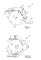
- Envelope sealer 10 which is operative in receiving and delivering envelopes in flap-up orientation.
- Envelope sealer 10 comprises a revolving drum 12 having a circumferential surface 14 and a substantially horizontal axis 16 about which drum 12 revolves.
- a vertical plane 18 (indicated by a dash-dot line) is defined through horizontal axis 16.
- Envelope sealer 10 further comprises moving endless belt means 20 including a belt surface area sector 22 which is disposed in contiguous proximity to the outer surface of revolving drum 12.
- Belt surface area sector 22 represents the concave surface of the part of the length of the belt of moving endless belt means 20 which is wrapped about a peripheral area portion 24 of revolving drum 12.
- Moving endless belt means 20 comprises one or more endless belts born on a plurality of rolls arranged,as shown in FIG. 1.
- the belt (or belts) has resiliently elastic properties, so that it accommodates envelopes nipped between moving endless belt means 20 and revolving drum 12.
- the resilient elastic properties of the belt facilitate a certain degree of conformance of its surface to envelopes thusly nipped and conveyed, whereby nipping pressure is substantially distributed over the envelope surface.
- the surface of revolving drum 12 can be also provided with resilient properties, for instance by employing a surface layer of resilient elastomeric material.
- At least one of the rolls of moving endless belt means 20 can be motor driven to move the belt in the direction shown by arrow 26.
- the belt moves at substantially the same speed as the periphery of revolving drum 12.
- Revolving drum 12 can be driven by the belt, or it can be separately motor driven. In the latter situation, the belt can be alternately driven by frictional contact with the revolving drum 12.
- area nip region 28 The region over which the belt (or belts) of moving endless belt means 20 contacts revolving drum 12, that is the region between belt surface area sector 22 and peripheral area portion 24, is defined as area nip region 28.
- Area nip region 28 includes a nip entry 30 and a nip exit 32 disposed respectively at the entry thereto and the exit therefrom.
- Envelopes are fed into nip entry 30 with flap hinge edge leading and in a substantially flap-up orientation by feeding means not illustrated here in detail.
- An envelope 34 is schematically indicated in a position during feeding to nip entry 30.
- Envelope 34 (preferably having its flap pre-moistened in the case of a wettable flap) is shown disposed on a platform 36 that is included in the feeding means.
- Platform 36 can be reciprocatingly movable in a horizontal plane toward and away from nip entry 30 so that an envelope received on platform 36 is moved thereby into nip entry 30.
- envelopes are seriatim transported on a conveyor in a horizontal direction, for instance orthogonally to the plane of the depiction, into the position shown by envelope 34, whereupon a reciprocating pusher device pushes each envelope from the conveyor surface into nip entry 30.
- Platform 36 can be envisaged as the pusher arm of such a pusher device.
- Other conventional means can be also employed to feed envelopes into position for sealing in envelope sealer 10.
- a conveyor can convey envelopes directly into nip entry 30 from the left hand side.
- envelopes need not necessarily be fed to envelope sealer 10 horizontally, but envelopes can be fed along an inclined plane.
- surface 40 can represent a conveyor surface for conveying sealed envelopes in a generally horizontal direction perpendicularly to the plane of the depiction. Alternately, surface 40 can represent a conveyor surface for conveying sealed envelopes toward the right. Other conventional conveying means can be used also to convey sealed envelopes away from envelope sealer 10. It should be understood that the orientation of delivered sealed envelopes need not necessarily be horizontal and surface 40 can be tilted in any direction to facilitate further conveying of sealed envelopes to a variety of other equipment.
- Delivery means aside from including revolving drum 12 and moving endless belt means 20, also includes blade means 42 having a leading edge 44 disposed in close proximity to the surface of revolving drum 12. Blade means 42 is operative in ensuring that envelopes egressing from nip exit 32 are reliably lifted off the surface of revolving drum 12 and are guided to delivery area 38.
- nip entry 30 is disposed substantially at the intersection of vertical plane 18 and circumferential surface 14. With respect to the depicted embodiment, it should be understood that a location of the nip entry 30 somewhat farther on one or the other side of vertical plane 18 can be equally effective.
- Nip exit 32 is disposed in a location substantially on the right hand side of vertical plane 18 so that area nip region 28 spans a relatively large area about the periphery of revolving drum 12.
- envelope sealer 10 is mounted in a common machine frame structure in the relationship indicated.
- the shaft of revolving drum 12 and the axles of the belt rollers are borne in appropriate bearings in such a frame structure, and blade means 42 is attached to this frame structure.
- platform 36 as well as the support base of the delivery area 38 are appropriately arranged in the required fixed or movable relationship in the machine frame structure.
- an envelope with its gummed flap (for example envelope 34) is fed into area nip region 28 at nip entry 30, is nipped therein, and has its flap closed. While being conveyed through area nip region 28 to nip exit 32, substantially normal pressure is exerted upon the envelope surfaces and its flap is sealed onto the envelope body and held in this compressed state for the travel time through area nip region 28. The sealed envelope is delivered from nip exit 32 to delivery area 38 in readiness for further processing.
- an envelope with its gummed flap for example envelope 34
- envelope sealer 50 (FIG. 2) and envelope sealer 50' (FIG. 3).
- envelope sealers 50 and 50' are somewhat similar to the embodiment shown in FIG. 1, but are particularly modified to include an envelope turnover capability.
- envelope sealers 50 and 50' are operative in receiving envelopes in flap-up orientation and delivering envelopes in flap-down orientation.
- Envelope sealers 50 and 50′ each comprise a revolving drum 52 having a similar structure, including similar elements, and functioning substantially in like manner as revolving drum 12 of FIG. 1, as hereinbefore described.
- Revolving drum 52 includes a circumferential surface 54 and a substantially horizontal axis 56 about which drum 52 revolves.
- a vertical plane 58 (indicated by a dash-dot line) is defined through horizontal axis 56.
- Envelope sealers 50 and 50' each further comprise moving endless belt means 60 including a belt surface area sector 62 which is disposed in contiguous proximity to the outer surface of revolving drum 52.
- Belt surface area sector 62 represents the concave surface of the part of the length of the belt of moving endless belt means 60 which is wrapped about a peripheral area portion 64 of revolving drum 52.
- Moving endless belt means 60 comprises one or more endless belts born on a plurality of rolls arranged as shown in FIGS. 2 and 3.
- the belt (or belts) has resiliently elastic properties, so that it accommodates envelopes nipped between moving endless belt means 60 and revolving drum 52.
- the resilient elastic properties of the belt facilitate a certain degree of conformance of its surface to envelopes thusly nipped and conveyed, whereby nipping pressure is substantially distributed over the envelope surface.
- the surface of revolving drum 52 can be also provided with resilient properties, for instance by employing a surface layer of resilient elastomeric material.
- At least one of the rolls of moving endless belt means 60 can be motor driven to move the belt in the direction shown by arrow 66.
- the belt moves at substantially the same speed as the periphery of revolving drum 52.
- Revolving drum 52 can be driven by the belt, or it can be separately motor driven. In the latter situation, the belt can be alternately driven by frictional contact with the revolving drum 52.
- area nip region 68 The region over which the belt (or belts) of moving endless belt means 60 contacts revolving drum 52, that is the region between belt surface area sector 62 and peripheral area portion 64, is defined as area nip region 68.
- Area nip region 68 includes a nip entry 70 and a nip exit 72 disposed respectively at the entry thereto and the exit therefrom.
- Envelopes are fed into nip entry 70 with flap hinge edge leading and in a substantially flap-up orientation by feeding means not illustrated here in detail.
- An envelope 76 is schematically indicated in a position during feeding to nip entry 70.
- Envelope 74 (having its flap pre-moistened) is shown disposed on a platform 76 that is comprised in feeding means.
- Platform 76 can be reciprocatingly movable in a horizontal plane toward and away from nip entry 70 so that an envelope received on platform 74 is moved thereby into nip entry 70.
- envelopes are seriatim transported on a conveyor in a horizontal direction, for instance orthogonally to the plane of the depiction, into the position shown by envelope 74, whereupon a reciprocating pusher device pushes each envelope from the conveyor surface into nip entry 70.
- Platform 76 can be envisaged as the pusher arm of such a pusher device.
- Other conventional means can be also employed to feed envelopes into position for sealing in envelope sealers 50 and 50'.
- a conveyor can convey envelopes directly into nip entry 70 from the left hand side.
- envelopes need not necessarily be fed to envelope sealers 50 and 50' horizontally, but envelopes can be fed along an inclined plane.
- surface 80 can represent a conveyor surface for conveying sealed envelopes in a generally horizontal direction perpendicularly to the plane of the depiction. Alternately, surface 80 can represent a conveyor surface for conveying sealed envelopes toward the left. Other conventional conveying means can be used also to convey sealed envelopes away from envelope sealers 50 and 50'. It should be understood that the orientation of delivered sealed envelopes need not necessarily be horizontal and surface 80 can be tilted in any direction to facilitate farther conveying of sealed envelopes to a variety of other equipment.
- Delivery means aside from including revolving drum 52 and moving endless belt means 60, also include blade means 82 having a leading edge 84 disposed in close proximity to the surface of revolving drum 52. Blade means 82 is operative in ensuring that envelopes egressing from nip exit 72 are reliably lifted off the surface of revolving drum 52 and are guided to delivery area 78.
- nip entry 70 is disposed substantially on the right side of vertical plane 58. With respect to the depicted embodiments, it should be understood that nip entry 70 can be disposed at the vertical plane 58 or somewhat to the left side of vertical plane 58 to be equally as effective.
- Nip exit 72 is disposed on the right side of vertical plane 58 in the embodiment of FIG. 2. In the embodiment of FIG. 3, nip exit 72 is disposed on the left side of vertical plane 58. The latter embodiment serves particularly for delivering sealed envelopes at a higher level than the level at which envelopes are delivered by the embodiment shown in FIG. 2.
- envelope sealers 50 and 50' are each mounted in a common machine frame structure in the relationship indicated.
- the shaft of revolving drum 52 and the axles of the belt rollers are born in appropriate bearings in such a frame structure, and blade means 82 is attached to this frame structure.
- platform 76 as well as the support base of the delivery area 78 are appropriately arranged in the required fixed or movable relationship in the machine frame structure.
- an envelope is fed into area nip region 68 at nip entry 70, is nipped therein, and has its flap closed. While being conveyed through area nip region 68 to nip exit 72, substantially normal pressure is exerted upon the envelope surfaces and its flap is sealed onto the envelope body and held in this compressed state for the travel time through area nip region 68.
- the sealed envelope is delivered from nip exit 72 to delivery area 78 in readiness for further processing.
- envelope sealers 50 and 50' include means for turning over envelopes while they are conveyed through area nip region 68. For instance, envelope 74 fed in flap-up orientation into area nip region 68 is delivered therefrom to delivery area 78 in flap-down orientation.
- FIGS.4 and 5 the embodiments shown therein basically differ from those depicted in FIGS.1-3 in that the envelopes are fed to the envelope sealers to a nip entry disposed in a lower portion of the revolving drum. Further, whereas the envelope sealer of FIG. 5 serves to seal envelopes without turnover, the envelope sealer of FIG. 4 includes means for turning over envelopes during sealing thereof. Thus envelopes fed to the envelope sealer of FIG. 4 in flap-up orientation are delivered therefrom in flap-down orientation.
- FIG. 4 shows an envelope feeder 150
- FIG. 5 shows an envelope feeder 150'. Accordingly, elements of envelope feeder 150' that are similar to elements of envelope feeder 150 will be designated by the same numeral primed.
- Envelope feeders 150 and 150' each comprise a revolving drum 152 and 152' having a similar structures, including similar elements, and functioning substantially in like manner as revolving drum 12 of FIG. 1, as hereinbefore described.
- Revolving drum 152 (152') includes a circumferential surface 154 (154') and a substantially horizontal axis 156 (156') about which drum 152 (152') revolves.
- Envelope sealers 150 and 150' further comprise moving endless belt means 160 and 160', each including a belt surface area sector 162 (162').
- Belt surface area sector 162 (162') is disposed in contiguous proximity to the outer surface of revolving drum 152 (152').
- Belt surface area sector 162 (162') represents the concave surface of the part of the length of the belt of moving endless belt means 160 (160') which is wrapped about a peripheral area portion 164 (164') of revolving drum 152 (152').
- Moving endless belt means 160 (160') comprises one or more endless belts born on a plurality of rolls arranged as shown in FIGS.4 and 5.
- the belt has resiliently elastic properties so that it accommodates envelopes nipped between moving endless belts 160 (160') and revolving drum 152 (152').
- the resilient elastic properties of the belt facilitate a certain degree of conformance of its surface to envelopes thusly nipped and conveyed, whereby nipping pressure is substantially distributed over the envelope surface.
- the surface of revolving drum 152 (152') can be also provided with resilient properties, for instance by employing a surface layer of resilient elastomeric material.
- At least one of the rolls of moving endless belt means 160 can be motor driven to move the belt in the direction shown by arrow 166 (166').
- the belt moves at substantially the same speed as the periphery of revolving drum 152 (152').
- Revolving drum 152 (152') can be driven by the belt, or it can be separately motor driven. In the latter situation, the belt can be alternately driven by frictional contact with the revolving drum 152 (152').
- Area nip region 168 (168') includes a nip entry 170 (170') and a nip exit 172 (172') disposed respectively at the entry thereto and the exit therefrom.
- Envelopes are fed toward nip entry 170 (170') with flap hinge edge leading and in a substantially flap-up orientation by feeding means not illustrated here in detail.
- An envelope 174 (174') is schematically indicated in a position during feeding toward nip entry 170 (170').
- the envelope 174 (174') is indicated in a position upon a fragmentally shown platform 176 (176') while being fed into a nip between an auxiliary roller 177 (177') and an extended portion of moving endless belt means 160 (160').
- the envelope is fed through this nip and farther upon moving endless belt means 160 (160') into nip entry 170 (170′) and therefrom through area nip region 168 (168′).
- One or more pressure rolls can be disposed above the extended portion of moving endless belt means 160 (160′) to assist envelope transport thereupon.
- envelopes are seriatim transported on a conveyor in a horizontal direction, for instance from left to right in the depiction, through the position shown by envelope 174 (174′), into the nip beneath auxilliary roller 177 (177').
- Platform 176 (176′) can be envisaged as representative of a feed conveyor or another conventional feed means for envelope transport.
- surface 180 (180') can represent a conveyor surface for conveying sealed envelopes in a generally horizontal direction perpendicularly to the plane of the depiction. Other conventional conveying means can be used also to convey sealed envelopes away from envelope sealers 150 and 150'. It should be understood that the orientation of delivered sealed envelopes need not necessarily be horizontal and surface 180 (180') can be tilted in any direction to facilitate farther conveying of sealed envelopes to a variety of other equipment.
- Delivery means aside from including revolving drum 152 (152') and moving endless belt means 160 (160'), also'include blade means 182 (182') having a leading edge 184 (184′) disposed in close proximity to the surface of revolving drum 152 (152'). Blade means 182 (182') is operative in ensuring that envelopes egressing from nip exit 172 (172') are reliably lifted off the surface of revolving drum 152 (152') and are guided to delivery area 178 (178′).
- nip entry 170 (170') is disposed substantially on the left side of vertical plane 158 (158'). With respect to the depicted embodiments, it should be understood that nip entry 170 (170') can be alternately disposed at the vertical plane 158 (158') or even somewhat to the right side of vertical plane 158 (158').
- Nip exit 172 (FIG. 4) is disposed on the left side of vertical plane 158. In the embodiment of FIG. 5, nip exit 172' is disposed on the right side of vertical plane 158′.
- envelope sealers 150 and 150′ are each mounted in a common machine frame structure in the relationship indicated.
- the shaft of revolving drum 152 (152') and the axles of the belt rollers are borne in appropriate bearings in such a frame structure, and blade means 182 (182′) is attached to this frame structure.
- platform 176 (176') as well as the support base of the delivery area 178 (178') are appropriately arranged in the required fixed or movable relationship in the machine frame structure.
- an envelope is fed to nip entry 170 (170') and through area nip region 168 (168'). While being conveyed through area nip region 168 (168') to nip exit 172 (172'), substantially normal pressure is exerted upon the envelope surfaces and its flap is sealed onto the envelope body and held in this compressed state for the travel time through area nip region 168 (168'). The sealed envelope is delivered from nip exit 172 (172') to delivery area 178 (178′) in readiness for further processing.
- envelope sealer 150 includes means for turning over envelopes while they are conveyed through area nip region 168. For instance, envelope 174 fed in flap-up orientation into area nip region 168 is delivered therefrom to delivery area 78 in flap-down orientation. Envelope sealer 150' (FIG. 5) does not provide envelope turnover.
Landscapes
- Package Closures (AREA)
Applications Claiming Priority (2)
| Application Number | Priority Date | Filing Date | Title |
|---|---|---|---|
| US52283190A | 1990-05-14 | 1990-05-14 | |
| US522831 | 1990-05-14 |
Publications (1)
| Publication Number | Publication Date |
|---|---|
| EP0459640A1 true EP0459640A1 (fr) | 1991-12-04 |
Family
ID=24082564
Family Applications (1)
| Application Number | Title | Priority Date | Filing Date |
|---|---|---|---|
| EP91304172A Withdrawn EP0459640A1 (fr) | 1990-05-14 | 1991-05-09 | Dispositif de fermeture d'enveloppe |
Country Status (3)
| Country | Link |
|---|---|
| EP (1) | EP0459640A1 (fr) |
| JP (1) | JPH04242523A (fr) |
| CA (1) | CA2041954A1 (fr) |
Families Citing this family (1)
| Publication number | Priority date | Publication date | Assignee | Title |
|---|---|---|---|---|
| JP4573735B2 (ja) * | 2005-08-31 | 2010-11-04 | 株式会社木下製作所 | 封緘部の糊付け検査方法及び装置 |
Citations (1)
| Publication number | Priority date | Publication date | Assignee | Title |
|---|---|---|---|---|
| US1850575A (en) * | 1926-05-17 | 1932-03-22 | Ralph G Whitlock Patents Inc | Machine for sealing letters |
-
1991
- 1991-05-07 CA CA 2041954 patent/CA2041954A1/fr not_active Abandoned
- 1991-05-09 EP EP91304172A patent/EP0459640A1/fr not_active Withdrawn
- 1991-05-10 JP JP13330091A patent/JPH04242523A/ja active Pending
Patent Citations (1)
| Publication number | Priority date | Publication date | Assignee | Title |
|---|---|---|---|---|
| US1850575A (en) * | 1926-05-17 | 1932-03-22 | Ralph G Whitlock Patents Inc | Machine for sealing letters |
Also Published As
| Publication number | Publication date |
|---|---|
| JPH04242523A (ja) | 1992-08-31 |
| CA2041954A1 (fr) | 1991-11-15 |
Similar Documents
| Publication | Publication Date | Title |
|---|---|---|
| US4753429A (en) | Collating station for inserting machine | |
| US4705157A (en) | Article turning assembly | |
| US4562684A (en) | Apparatus for applying a tubular member over a container | |
| US4546963A (en) | Sheet separation apparatus | |
| JPH08500568A (ja) | 平らな物品のフィーダー用の供給前のずらし置き装置 | |
| US3700232A (en) | Sheet stacking apparatus | |
| US5950399A (en) | Apparatus and method for inserting a product into an envelope and closing same | |
| GB2092558A (en) | Mail sorting machine | |
| US3810612A (en) | Method and apparatus for handling sheet materials, signatures and the like | |
| CN1299957C (zh) | 药包搬送装置 | |
| CA2041954A1 (fr) | Appareil a cacheter les enveloppes | |
| US6948540B2 (en) | Envelope sealing apparatus | |
| US6425579B1 (en) | Low friction envelope feeder | |
| JP2721180B2 (ja) | 郵便物の押印装置 | |
| JPH0211409Y2 (fr) | ||
| JPH0262455B2 (fr) | ||
| JPS6225583B2 (fr) | ||
| JPH0541539B2 (fr) | ||
| AU2009288645B2 (en) | Transporting apparatus for web products and related methods | |
| JPH0373757A (ja) | 紙折り装置 | |
| EP0869094A3 (fr) | Transport de feuilles | |
| JPS62146864A (ja) | 紙葉類の表裏反転装置 | |
| JPH02242711A (ja) | 小包等を包装するために使用される改良された封止フィルム付着用機械 | |
| JPH0731740U (ja) | 封筒搬送装置 | |
| CA2031930C (fr) | Appareil servant a ouvrir les enveloppes |
Legal Events
| Date | Code | Title | Description |
|---|---|---|---|
| PUAI | Public reference made under article 153(3) epc to a published international application that has entered the european phase |
Free format text: ORIGINAL CODE: 0009012 |
|
| AK | Designated contracting states |
Kind code of ref document: A1 Designated state(s): CH DE FR GB LI |
|
| STAA | Information on the status of an ep patent application or granted ep patent |
Free format text: STATUS: THE APPLICATION IS DEEMED TO BE WITHDRAWN |
|
| 18D | Application deemed to be withdrawn |
Effective date: 19920605 |