EP0460227A1 - Systeme d'asservissement de poursuite d'arbre additionnel pour robot - Google Patents
Systeme d'asservissement de poursuite d'arbre additionnel pour robot Download PDFInfo
- Publication number
- EP0460227A1 EP0460227A1 EP91900926A EP91900926A EP0460227A1 EP 0460227 A1 EP0460227 A1 EP 0460227A1 EP 91900926 A EP91900926 A EP 91900926A EP 91900926 A EP91900926 A EP 91900926A EP 0460227 A1 EP0460227 A1 EP 0460227A1
- Authority
- EP
- European Patent Office
- Prior art keywords
- robot
- supplementary axis
- posture
- additional shaft
- supplementary
- Prior art date
- Legal status (The legal status is an assumption and is not a legal conclusion. Google has not performed a legal analysis and makes no representation as to the accuracy of the status listed.)
- Granted
Links
Images


Classifications
-
- G—PHYSICS
- G05—CONTROLLING; REGULATING
- G05B—CONTROL OR REGULATING SYSTEMS IN GENERAL; FUNCTIONAL ELEMENTS OF SUCH SYSTEMS; MONITORING OR TESTING ARRANGEMENTS FOR SUCH SYSTEMS OR ELEMENTS
- G05B19/00—Program-control systems
- G05B19/02—Program-control systems electric
- G05B19/418—Total factory control, i.e. centrally controlling a plurality of machines, e.g. direct or distributed numerical control [DNC], flexible manufacturing systems [FMS], integrated manufacturing systems [IMS] or computer integrated manufacturing [CIM]
- G05B19/41815—Total factory control, i.e. centrally controlling a plurality of machines, e.g. direct or distributed numerical control [DNC], flexible manufacturing systems [FMS], integrated manufacturing systems [IMS] or computer integrated manufacturing [CIM] characterised by the cooperation between machine tools, manipulators and conveyor or other workpiece supply system, workcell
- G05B19/4182—Total factory control, i.e. centrally controlling a plurality of machines, e.g. direct or distributed numerical control [DNC], flexible manufacturing systems [FMS], integrated manufacturing systems [IMS] or computer integrated manufacturing [CIM] characterised by the cooperation between machine tools, manipulators and conveyor or other workpiece supply system, workcell manipulators and conveyor only
-
- G—PHYSICS
- G05—CONTROLLING; REGULATING
- G05B—CONTROL OR REGULATING SYSTEMS IN GENERAL; FUNCTIONAL ELEMENTS OF SUCH SYSTEMS; MONITORING OR TESTING ARRANGEMENTS FOR SUCH SYSTEMS OR ELEMENTS
- G05B2219/00—Program-control systems
- G05B2219/30—Nc systems
- G05B2219/36—Nc in input of data, input key till input tape
- G05B2219/36448—Teaching, consider workpoint on workpiece temporarily as tip of end effector
-
- G—PHYSICS
- G05—CONTROLLING; REGULATING
- G05B—CONTROL OR REGULATING SYSTEMS IN GENERAL; FUNCTIONAL ELEMENTS OF SUCH SYSTEMS; MONITORING OR TESTING ARRANGEMENTS FOR SUCH SYSTEMS OR ELEMENTS
- G05B2219/00—Program-control systems
- G05B2219/30—Nc systems
- G05B2219/39—Robotics, robotics to robotics hand
- G05B2219/39101—Cooperation with one or more rotating workpiece holders, manipulators
-
- G—PHYSICS
- G05—CONTROLLING; REGULATING
- G05B—CONTROL OR REGULATING SYSTEMS IN GENERAL; FUNCTIONAL ELEMENTS OF SUCH SYSTEMS; MONITORING OR TESTING ARRANGEMENTS FOR SUCH SYSTEMS OR ELEMENTS
- G05B2219/00—Program-control systems
- G05B2219/30—Nc systems
- G05B2219/50—Machine tool, machine tool null till machine tool work handling
- G05B2219/50353—Tool, probe inclination, orientation to surface, posture, attitude
-
- Y—GENERAL TAGGING OF NEW TECHNOLOGICAL DEVELOPMENTS; GENERAL TAGGING OF CROSS-SECTIONAL TECHNOLOGIES SPANNING OVER SEVERAL SECTIONS OF THE IPC; TECHNICAL SUBJECTS COVERED BY FORMER USPC CROSS-REFERENCE ART COLLECTIONS [XRACs] AND DIGESTS
- Y02—TECHNOLOGIES OR APPLICATIONS FOR MITIGATION OR ADAPTATION AGAINST CLIMATE CHANGE
- Y02P—CLIMATE CHANGE MITIGATION TECHNOLOGIES IN THE PRODUCTION OR PROCESSING OF GOODS
- Y02P90/00—Enabling technologies with a potential contribution to greenhouse gas [GHG] emissions mitigation
- Y02P90/02—Total factory control, e.g. smart factories, flexible manufacturing systems [FMS] or integrated manufacturing systems [IMS]
Definitions
- the present invention relates to a method of controlling a robot with a supplementary axis, whereby a robot is controlled by following a supplementary axis, and more particularly, to a method of controlling a robot with a supplementary axis, whereby the robot is automatically moved in response to a manual jog-run of the supplementary axis.
- a table on which a workpiece is fixed is designed to rotate or move in a direction perpendicular to such a rotation, the table is controlled by a supplementary axis control circuit incorporated in a robot control unit, and this facilitates the control of the posture of the robot when performing a welding or other machining.
- the object of the present invention is to solve the above problem and provide a method of controlling a robot with a supplementary axis, to thereby cause the robot to automatically follow a manual feed of the supplementary axis.
- the present invention provides a method of controlling a robot with a supplementary axis, to thereby control the tool cusp point (TCP) of the robot through the supplementary axis, in which the supplementary axis is manually fed, a coordinate position of the supplementary axis is read, coordinates and a posture of the tool cusp point are determined so that the relative position and posture of the supplementary axis coincide with said tool cusp point of the robot, and the tool cusp point is then moved accordingly.
- TCP tool cusp point
- the resulting new coordinate position is read through a supplementary axis control circuit, a position and coordinates of the tool cusp point that correspond to such a movement are determined by a microprocessor which controls the robot, and the arm of the robot is positioned in accordance with the new position and coordinates of the tool cusp point.
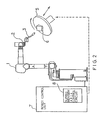
- FIG. 2 is a configuration diagram of a robot system according to the embodiment of the invention, wherein a torch 3 is installed on the end of a wrist 2 of a robot 1, a table 5 is controlled by a supplementary axis control circuit 8 incorporated in a robot control unit 7, and the table 5 is controlled to rotate and move in a direction perpendicular to the rotation. A workpiece 6 is fixed on the table 5.
- the table 5 is rotated or manually jog-run in a vertical direction through a control panel, not shown in the drawing, a microprocessor in the robot control unit 7 reads the coordinates of the table in the supplementary axis control circuit 8 and performs a control such that the positional relationship between the end of the torch 3 and the workpiece remains unchanged.
- FIG. 3 shows the relationship between the tool cusp point (TCP) and the coordinate system of the supplementary axis.
- a coordinate system of a robot tool cusp point (TCP) 12 exists with respect to a base coordinate system 11 of the robot, and a supplementary axis base coordinate system 21 relating to those coordinate systems exists. This is the coordinate system of the table 5 in FIG. 2.
- a coordinate system 22 of the supplementary axis exists with respect to the base coordinate system 21 of the supplementary axis.
- matrix of a coordinate change from an origin AP1 of the coordinate system 22 of the supplementary axis to an origin RP1 of the coordinate system 12 of the TCP12 is taken as B.
- the supplementary axis is manually jog-run to a point AP2 by a coordinate change matrix A.
- a coordinate change matrix P is a coordinate change matrix from the point AP2 to a point RP2.
- the coordinate change matrix R is the coordinate change matrix that determines the movement of the TCP12.
- FIG. 1 is a flowchart of the method of controlling a robot with a supplementary axis according to the present invention.
- a number that follows S indicates a step number.
- the tool cusp point (TCP) is automatically moved in accordance with the new position and posture of the supplementary axis such as a table, and this eliminates the need to move the robot or control the posture of the robot.
- the present invention is described in connection with a welding robot, but the invention may be applied in a similar way to other robots having tables or the like which are controlled through supplementary axes.
- the robot is automatically adjusted to maintain a constant position and posture thereof by following new coordinates resulting from a manual feed of the supplementary axis. Therefore, even when the supplementary axis is moved, there is no need to control the position or posture of the robot, and thus the teaching efficiency is improved.
Landscapes
- Engineering & Computer Science (AREA)
- General Engineering & Computer Science (AREA)
- Manufacturing & Machinery (AREA)
- Quality & Reliability (AREA)
- Physics & Mathematics (AREA)
- General Physics & Mathematics (AREA)
- Automation & Control Theory (AREA)
- Manipulator (AREA)
- Numerical Control (AREA)
Abstract
Applications Claiming Priority (3)
| Application Number | Priority Date | Filing Date | Title |
|---|---|---|---|
| JP335833/89 | 1989-12-25 | ||
| JP1335833A JPH03196981A (ja) | 1989-12-25 | 1989-12-25 | ロボットの付加軸追従制御方式 |
| PCT/JP1990/001645 WO1991009710A1 (fr) | 1989-12-25 | 1990-12-14 | Systeme d'asservissement de poursuite d'arbre additionnel pour robot |
Publications (3)
| Publication Number | Publication Date |
|---|---|
| EP0460227A1 true EP0460227A1 (fr) | 1991-12-11 |
| EP0460227A4 EP0460227A4 (en) | 1992-03-11 |
| EP0460227B1 EP0460227B1 (fr) | 1995-09-13 |
Family
ID=18292916
Family Applications (1)
| Application Number | Title | Priority Date | Filing Date |
|---|---|---|---|
| EP91900926A Expired - Lifetime EP0460227B1 (fr) | 1989-12-25 | 1990-12-14 | Systeme d'asservissement de poursuite d'arbre additionnel pour robot |
Country Status (5)
| Country | Link |
|---|---|
| US (1) | US5313563A (fr) |
| EP (1) | EP0460227B1 (fr) |
| JP (1) | JPH03196981A (fr) |
| DE (1) | DE69022407T2 (fr) |
| WO (1) | WO1991009710A1 (fr) |
Cited By (1)
| Publication number | Priority date | Publication date | Assignee | Title |
|---|---|---|---|---|
| CN106325302A (zh) * | 2015-06-17 | 2017-01-11 | 电子科技大学 | 一种移动物体位置跟踪平台、跟踪装置及跟踪方法 |
Families Citing this family (7)
| Publication number | Priority date | Publication date | Assignee | Title |
|---|---|---|---|---|
| JP3070329B2 (ja) * | 1993-03-31 | 2000-07-31 | 松下電器産業株式会社 | 産業用ロボットシステム |
| EP0785492B1 (fr) * | 1995-08-09 | 2001-11-07 | Fanuc Ltd | Robot fonctionnant par petits deplacements |
| DE102006056051B4 (de) | 2006-11-28 | 2018-09-20 | Robert Bosch Gmbh | Roboter mit Steuerung für Zusatzachsen |
| DE102011084412A1 (de) * | 2011-10-13 | 2013-04-18 | Kuka Roboter Gmbh | Robotersteuerungsverfahren |
| JP2014024162A (ja) * | 2012-07-27 | 2014-02-06 | Seiko Epson Corp | ロボットシステム、ロボット制御装置、ロボット制御方法及びロボット制御プログラム |
| US10969760B2 (en) | 2018-04-12 | 2021-04-06 | Faro Technologies, Inc. | Coordinate measurement system with auxiliary axis |
| US11874101B2 (en) | 2018-04-12 | 2024-01-16 | Faro Technologies, Inc | Modular servo cartridges for precision metrology |
Family Cites Families (10)
| Publication number | Priority date | Publication date | Assignee | Title |
|---|---|---|---|---|
| SE7603703L (sv) * | 1976-03-26 | 1977-09-27 | Retab Ab | Forfarande vid styrning av en industrirobot |
| JPS60193016A (ja) * | 1984-03-14 | 1985-10-01 | Toyota Motor Corp | ロボツト装置 |
| JPS60246407A (ja) * | 1984-05-22 | 1985-12-06 | Toyoda Mach Works Ltd | 追従式ロボツト装置 |
| JPS6125207A (ja) * | 1984-07-12 | 1986-02-04 | Fanuc Ltd | ツ−ル座標系の設定方式 |
| JPS6132113A (ja) * | 1984-07-23 | 1986-02-14 | Seiko Instr & Electronics Ltd | ロボツト制御方式 |
| JPS6142004A (ja) * | 1984-08-06 | 1986-02-28 | Toyota Central Res & Dev Lab Inc | 追従ロボツト装置 |
| JPS61281305A (ja) * | 1985-06-06 | 1986-12-11 | Toyota Motor Corp | 多関節ロボツト制御装置 |
| JPH0789287B2 (ja) * | 1985-11-07 | 1995-09-27 | 三菱電機株式会社 | ロボットのプログラミング方法 |
| SE464855B (sv) * | 1986-09-29 | 1991-06-24 | Asea Ab | Foerfarande vid en industrirobot foer kalibrering av en sensor |
| JPH079606B2 (ja) * | 1988-09-19 | 1995-02-01 | 豊田工機株式会社 | ロボット制御装置 |
-
1989
- 1989-12-25 JP JP1335833A patent/JPH03196981A/ja active Pending
-
1990
- 1990-12-14 WO PCT/JP1990/001645 patent/WO1991009710A1/fr not_active Ceased
- 1990-12-14 EP EP91900926A patent/EP0460227B1/fr not_active Expired - Lifetime
- 1990-12-14 US US07/752,444 patent/US5313563A/en not_active Expired - Lifetime
- 1990-12-14 DE DE69022407T patent/DE69022407T2/de not_active Expired - Fee Related
Cited By (1)
| Publication number | Priority date | Publication date | Assignee | Title |
|---|---|---|---|---|
| CN106325302A (zh) * | 2015-06-17 | 2017-01-11 | 电子科技大学 | 一种移动物体位置跟踪平台、跟踪装置及跟踪方法 |
Also Published As
| Publication number | Publication date |
|---|---|
| EP0460227B1 (fr) | 1995-09-13 |
| DE69022407T2 (de) | 1996-02-29 |
| US5313563A (en) | 1994-05-17 |
| EP0460227A4 (en) | 1992-03-11 |
| JPH03196981A (ja) | 1991-08-28 |
| DE69022407D1 (de) | 1995-10-19 |
| WO1991009710A1 (fr) | 1991-07-11 |
Similar Documents
| Publication | Publication Date | Title |
|---|---|---|
| JP3476288B2 (ja) | Yagカッティングツールを用いた立体加工装置 | |
| EP0216930B1 (fr) | Systeme de determination des coordonnees rectangualaires d'une piece a usiner par un robot | |
| EP0416123A1 (fr) | Procede d'intervention manuelle pour un robot industriel | |
| EP0228471A4 (fr) | Systeme de commande de robots. | |
| EP0400154A1 (fr) | Procede de commande de robot pouvant etre corrige manuellement | |
| EP0194314A1 (fr) | Systeme permettant de commander la position d'un outil | |
| EP0460227A1 (fr) | Systeme d'asservissement de poursuite d'arbre additionnel pour robot | |
| EP0380678A4 (en) | Method of controlling tool attitude of a robot | |
| EP0188626A1 (fr) | Systeme de correction de la position d'un outil | |
| JPH05108123A (ja) | ツール先端位置補正方法 | |
| CN105900026B (zh) | 数控装置 | |
| JPS625408A (ja) | 関節形ロボツトの制御方式 | |
| JPH06134652A (ja) | 数値制御工作機械のロボットハンドの制御方法 | |
| JP3086172B2 (ja) | 産業用ロボットの制御装置 | |
| EP0181406A1 (fr) | Procede de commande d'un robot | |
| JPH05216516A (ja) | レーザ加工機 | |
| CN101893870A (zh) | 四轴加工机用数值控制装置 | |
| JP2640653B2 (ja) | 数値制御工作機械の手動同期送り機構 | |
| JPH0699381A (ja) | 視覚センサ付きロボットの制御方法 | |
| JPH03109606A (ja) | 工具補正方式 | |
| JP2841364B2 (ja) | 加工装置の位置決め方法 | |
| CZ39002U1 (cs) | Zařízení pro optimalizaci úhlových souřadnic jednotlivých kloubů šestiosého robotu | |
| JP2000127018A (ja) | 回転駆動型工具及びそれを用いた加工装置 | |
| JPH0454604A (ja) | 3次元工具経補正機能を有する数値制御装置 | |
| JPH1153013A5 (fr) |
Legal Events
| Date | Code | Title | Description |
|---|---|---|---|
| PUAI | Public reference made under article 153(3) epc to a published international application that has entered the european phase |
Free format text: ORIGINAL CODE: 0009012 |
|
| 17P | Request for examination filed |
Effective date: 19910906 |
|
| AK | Designated contracting states |
Kind code of ref document: A1 Designated state(s): DE FR GB |
|
| A4 | Supplementary search report drawn up and despatched |
Effective date: 19920120 |
|
| AK | Designated contracting states |
Kind code of ref document: A4 Designated state(s): DE FR GB |
|
| 17Q | First examination report despatched |
Effective date: 19940505 |
|
| GRAA | (expected) grant |
Free format text: ORIGINAL CODE: 0009210 |
|
| AK | Designated contracting states |
Kind code of ref document: B1 Designated state(s): DE FR GB |
|
| PG25 | Lapsed in a contracting state [announced via postgrant information from national office to epo] |
Ref country code: FR Effective date: 19950913 |
|
| REF | Corresponds to: |
Ref document number: 69022407 Country of ref document: DE Date of ref document: 19951019 |
|
| PG25 | Lapsed in a contracting state [announced via postgrant information from national office to epo] |
Ref country code: GB Effective date: 19951214 |
|
| EN | Fr: translation not filed | ||
| PLBE | No opposition filed within time limit |
Free format text: ORIGINAL CODE: 0009261 |
|
| STAA | Information on the status of an ep patent application or granted ep patent |
Free format text: STATUS: NO OPPOSITION FILED WITHIN TIME LIMIT |
|
| GBPC | Gb: european patent ceased through non-payment of renewal fee |
Effective date: 19951214 |
|
| 26N | No opposition filed | ||
| PGFP | Annual fee paid to national office [announced via postgrant information from national office to epo] |
Ref country code: DE Payment date: 20081126 Year of fee payment: 19 |
|
| PG25 | Lapsed in a contracting state [announced via postgrant information from national office to epo] |
Ref country code: DE Free format text: LAPSE BECAUSE OF NON-PAYMENT OF DUE FEES Effective date: 20100701 |