EP0460406B1 - Direction assistée - Google Patents
Direction assistée Download PDFInfo
- Publication number
- EP0460406B1 EP0460406B1 EP91107209A EP91107209A EP0460406B1 EP 0460406 B1 EP0460406 B1 EP 0460406B1 EP 91107209 A EP91107209 A EP 91107209A EP 91107209 A EP91107209 A EP 91107209A EP 0460406 B1 EP0460406 B1 EP 0460406B1
- Authority
- EP
- European Patent Office
- Prior art keywords
- steering
- signal
- detected signal
- motor
- shaft
- Prior art date
- Legal status (The legal status is an assumption and is not a legal conclusion. Google has not performed a legal analysis and makes no representation as to the accuracy of the status listed.)
- Expired - Lifetime
Links
- 238000001514 detection method Methods 0.000 claims description 10
- 230000009467 reduction Effects 0.000 description 9
- 230000007246 mechanism Effects 0.000 description 8
- 238000010586 diagram Methods 0.000 description 4
- 230000007935 neutral effect Effects 0.000 description 4
- 238000000034 method Methods 0.000 description 3
- 230000008569 process Effects 0.000 description 3
- 229920006395 saturated elastomer Polymers 0.000 description 3
- 238000009738 saturating Methods 0.000 description 2
- 230000007423 decrease Effects 0.000 description 1
- 238000006073 displacement reaction Methods 0.000 description 1
- ZZUFCTLCJUWOSV-UHFFFAOYSA-N furosemide Chemical compound C1=C(Cl)C(S(=O)(=O)N)=CC(C(O)=O)=C1NCC1=CC=CO1 ZZUFCTLCJUWOSV-UHFFFAOYSA-N 0.000 description 1
- 238000009434 installation Methods 0.000 description 1
- 230000002093 peripheral effect Effects 0.000 description 1
- 230000004044 response Effects 0.000 description 1
Images


Classifications
-
- B—PERFORMING OPERATIONS; TRANSPORTING
- B62—LAND VEHICLES FOR TRAVELLING OTHERWISE THAN ON RAILS
- B62D—MOTOR VEHICLES; TRAILERS
- B62D5/00—Power-assisted or power-driven steering
- B62D5/04—Power-assisted or power-driven steering electrical, e.g. using an electric servo-motor connected to, or forming part of, the steering gear
- B62D5/0457—Power-assisted or power-driven steering electrical, e.g. using an electric servo-motor connected to, or forming part of, the steering gear characterised by control features of the drive means as such
- B62D5/046—Controlling the motor
- B62D5/0466—Controlling the motor for returning the steering wheel to neutral position
Definitions
- the present invention relates to an electric power steering apparatus assisting steering force of a steering wheel with the rotating force of a motor.
- GB 2188891 A discloses an electric power steering apparatus for assisting steering force by driving a motor based on the torque detected by steering torque detecting means and the steering speed detected by steering rotation detecting means.
- the compensating means outputs a restricting signal smaller than the maximum motor return rotation control signal based on the vehicle speed detected by the vehicle speed detecting means to the motor controlling means so as to drive the motor. That is, the motor return rotation control signal which decreases according to the increase of the vehicle speed is restricted by the restricting signal so that the return performance to the neutral position at a low speed is improved and thus the return stability at a high speed is also improved.
- a further electric power steering apparatus which provides a driver a comfortable steering feeling by driving a motor for assisting steering force on the basis of a detected result of a steering torque exerted on a steering wheel and by assisting force required for steering a vehicle with turning force of the motor.
- Such conventional electric power steering apparatus has a problem that when the steering wheel is returning to the neutral position upon receipt of an input from a tyre, the returning movement is hindered by a moment of inertia of a rotor of a motor and frictional resistance of a reduction gear coupled to an output shaft of the motor. Therefore, a detector for detecting a steering angle, e.g., a rotary sensor or stroke sensor, etc. is installed on a rack shaft, steering shaft or motor to overcome the problem by driving the motor with a current corresponding to the detected steering angle, and the steering wheel is returned to the neutral position by the torque of the motor.
- a detector for detecting a steering angle e.g., a rotary sensor or stroke sensor, etc.
- a power steering apparatus to solve such problems as the poor response due to the inertia of the motor, friction of the reduction gear disposed between the motor and the steering mechanism, and phase delay in an electric circuit by differentiating a detected signal of a torque sensor thereby to adjust the driving current of the motor is disclosed in Japanese Patent Application Laid-Open No. 61-115771 (115771-1986).
- the steering mechanism by differentiating the detected signal of the torque sensor and adding it to a temporary control value obtained corresponding to the detected signal of the torque sensor, the steering mechanism is driven in correspondence to the steering torque detected by the torque sensor without a time delay.
- the relation between the torque and the temporary control value of the driving current of the motor is preliminarily set as a function.
- the temporary control value of the driving current for the motor is set from the detected signal of the torque sensor by use of the function, and the differentiated signal of the detected signal is added to the temporary control value to determine the final control value of the driving current.
- the driving current for the motor is controlled by the determined control value thereby to assist steering force.
- the detected signal to be differentiated is the same as the detected signal for determining the temporary control value of the driving current.
- a voltage of the detected signal for determining the temporary control value is corresponding to the detected value of the steering torque.
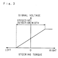
- Fig. 3 is a graph showing an example of the relation between the steering torque and signal voltage, in which the vertical axis represents the signal voltage and the horizontal axis represents the steering torque.
- the responsive voltage is saturated.
- the range necessary to assist steering force under the normal cruising condition is an effective detection width of the steering torque. Since the signal to be differentiated is the same signal as the detected signal for determining the temporary control value of the driving current, the differentiating is significant within the range of the effective detection width.
- the detected signal of the steering torque to be differentiated is the same as the detected signal to determine the temporary control value of the driving current, and the voltage signal corresponding to the steering torque is saturated when the steering torque is out of the effective detection width. Therefore, the differential value becomes always 0 even if the steering torque is out of the effective detection width, the differentiating is not effective and the responding efficiency of the steering mechanism worsens.
- the present invention has been devised to solve the aforementioned problems.
- a first object of the present invention is to provide a inexpensive power steering apparatus capable of controlling a motor for assisting steering force without using a steering angle detector when a steering wheel is being returned.
- a second object of the present invention is to provide a power steering apparatus capable of differentiating the steering torque in a wider range, to control the driving current of an assisting motor, thereby achieving good responding efficiency of a steering mechanism to the steering torque in the wider range.
- Fig. 1 is a partially broken sectional view of a power steering apparatus related to the invention.
- Fig. 2 is an enlarged sectional view along line II-II of Fig. 1.
- reference numeral 1 designates a rack shaft inserted concentrically within a cylindrical rack shaft case 2 fixed at a part of a vehicle body with its longitudinal direction as right-left direction.
- Numeral 3 is a pinion shaft supported rotatably in the state that the shaft center thereof intersects obliquely against the rack shaft 1 at the inside of a pinion shaft case 4 connected following the vicinity of one end portion of the rack shaft 2.
- the pinion shaft 3 as shown in Fig. 2, consists of an upper shaft 3a and a lower shaft 3b connected coaxially with each other through a torsion bar 5, the upper shaft 3a being supported inside of the pinion shaft case 4 by a ball bearing 40 with its upper end portion interlockingly combined to a steering wheel through a universal joint not shown. And the lower shaft 3b at the neighborhood position of the upper end portion is supported inside of the pinion shaft case 4 by a four-point contact ball bearing 41 in the state that the proper length of the under portion thereof is projected from a downside opening of the pinion shaft case 4.
- the four-point contact ball bearing 41 is fitted from outside to the lower shaft 3b from lower end portion side, and is positioned outside of the lower shaft 3b in the axial direction with both sides of the inner ring being hold, by steps formed in the vicinity of the upper end portion of the lower shaft 3b and collar 42 fixed from outside from the lower end portion side and caulked to the peripheral surface.
- pinion teeth 30 in an appropriate length are formed in the axial direction thereof.
- the pinion shaft case 4 is fixed at the upper side of aforesaid rack shaft case 2 by fixing bolt 44, the pinion teeth 30 engages with rack teeth 10 formed at a position a little closer to one end portion of the rack shaft 1 in the axial direction thereof in an appropriate length inside of the rack shaft case 2, making the lower shaft 3b with rack shaft 1 engage, with their shaft centers intersect obliquely with each other.
- the lower shaft 3b is extended downward further from the position of engagement with the rack shaft 1, a big bevel gear 31 with the teeth-formed face thereof tilting downward being fittedly mounted coaxially with the lower shaft 3b at the lower end portion thereof.
- the lower shaft 3b is supported by needle roller bearing 33 in a bevel gear housing 20 connected following the downside of the rack shaft case 2 in the state of surrounding the big bevel gear 31. Accordingly, the lower shaft 3b is supported at both sides of the position of engagement of the rack teeth 10 with the pinion teeth 30 by the four-point contact ball bearing 41 and needle roller bearing 33, whereby flexing quantity of the lower shaft 3b at the position of engagement is kept within the tolerance.
- a pressing piece 12 for pressing the rack shaft 1 by biasing force of a pressing spring 11 forward the pinion shaft 3 is provided so that the rack teeth 10 and the pinion teeth 30 can be engaged without any gap.
- the rack shaft 1 is, at the position of engagement, supported by the pressing piece 12 and the lower shaft 3b in the state that it is held from both sides of radial direction as well as it is supported by bearing bush 13 fitted into an end portion of the rack shaft case 2 opposite to the connected position of the pinion shaft case 4 with itself, it being movable freely in its axial direction inside of the rack shaft case 2.
- Both right and left end portions of the rack shaft 1 projected respectively at both sides of the rack shaft case 2 is connected to tie rods 15, 15 stretching respectively to the right and left wheels not shown through respective ball and socket joints 14, 14, the wheels being steered to right or left according to the movement of the rack shaft 1 in the axial direction thereof.
- reference numeral 6 designates a torque sensor for detecting steering torque exerted on the steering wheel.
- the torque sensor 6 uses a potentiometer comprising a resistance holding member 60 which is outfitted to the upper shaft 3a, rotates therewith, and at the downside end surface, forms a circular resistance with the shaft center of the upper shaft 3a being the center, and a detecting piece holding member 61 which is outfitted to the lower shaft 3b, rotates therewith and, at the upside end surface, forms a detecting piece which slidely-contacts to a point in a radial direction on the resistance.
- the upper shaft 3a of the pinion shaft 3 rotates around the axial shaft according to the rotation of the steering wheel, however, road surface resistance acting upon the wheels acts upon the lower shaft 3b through the rack shaft 1, thereby, torsion corresponding to the steering torque exerted on the steering wheel is produced at torsion bar 5 interposed between the two shafts.
- a torque sensor 6 outputs relative displacement in the circumferential direction created between the upper shaft 3a and the lower shaft 3b accompanying the torsion of the torsion bar 5, as a potential corresponding to slidely contact position of the detecting piece with the resistance and in the case where the torsion is not created at the torsion bar 5, in other words, in the case where the steering operation is not performed, it is initialized so as to output the specified reference potential.
- the output signal of the torque sensor 6 is inputted in a control unit 7 which compares the signal with the reference potential to recognize the direction and size of the steering torque, then generates a driving signal to a motor 8 for assisting steering force provided in such a way as described later.
- the motor 8 for assisting steering force is to transmit the turning force thereof to aforementioned lower shaft 3b through an electromagnetic clutch 16, epicycle reduction gear 9 and small bevel gear 32 which engages with the big bevel gear 31 and is smaller than the big bevel gear 31 in diameter.
- the electromagnetic clutch 16 consists of a coil unit 161 which is annular in shape and fixed to a middle case 81 of the motor 8, a moving unit 162 which is outfitted at one side of a rotation axis 80 of the motor 8 coaxially therewith and rotates with the rotation axis 80, and engaging part 163 which is discoid in shape, faces the moving unit 162 and engages with the moving unit 162 by electromagnetic force caused by power supply to the coil unit 161, performing engaging and disengaging of turning force of the motor 8.
- the epicycle reduction gear 9 consists of a sun shaft 90 which is fitted into the engaging part 163, rotates and has a sun gear supported at one end thereof by a bearing fitted into the moving unit 162, and supported at the other end by a bearing fitted into a planet carrier 93 to be described later, an outer ring 91 which is circular in shape and fixed to a casing end surface 82 of the motor 8 coaxially with the rotation axis 80, a plurality of planet gears 92, 92 ⁇ which rotatably contacts with the inner surface of the outer ring 91 and with the outer surface of the sun gear of the sun shaft 90 respectively, autorotate around the shaft center respectively as well as revolve around the shaft center of the sun gear, and the planet carrier 93 which supports rotatably respective planet gears 92, 92 ⁇ .
- the epicycle reduction gear 9 has a smaller outer diameter than that of the motor 8 and is integrated with the motor 8 and electromagnetic clutch 16 at one side of the rotation axis 80.
- An output shaft 94 of the epicycle reduction gear 9 is fitted into and fixed at a position of the shaft center of the planet carrier 93 which is positioned coaxially with the rotation axis 80 of the motor 8, and is projected in an appropriate length outside of the casing.
- the small bevel gear 32 is fixedly mounted with its teeth-formed face turned toward the tip portion side, the small bevel gear 32 being constructed so as to rotate, together with the output shaft 94, corresponding to the revolution of the planet gears 92, 92 ⁇ .
- the motor 8, electromagnetic clutch 16 and epicycle reduction gear 9 are fixed onto a blacket 2a provided outside of the rack shaft case 2, in the state that these shaft centers are approximately parallel to the shaft center of the rack shaft 1 and are fitted into the bevel gear housing 20 with the small bevel gear 32 being inside. And at the inside of the aforesaid housing 20, the small bevel gear 32 is engaged with the big bevel gear 31 fixedly mounted at the lower end portion of aforesaid lower shaft 3b.
- Backlash adjustment between the big bevel gear 31 and the small bevel gear 32, in fitting the epicycle reduction gear 9 into the bevel gear housing 20, can be performed easily by changing thickness and/or number of shims to be interposed at the abutting portion of the casing of the epicycle reduction gear 9 with the bevel gear housing 20.
- To the control unit 7 is inputted an output signal from a vehicle speed sensor 18 besides the aforementioned output signal from the torque sensor, whereby a driving signal for driving the motor 8 is outputted in a manner as will be described later.
- control unit 7 The operation of the control unit 7 will be depicted hereinafter.
- Fig. 4 is a block diagram showing the structure of an embodiment of a control system of the power steering apparatus of the invention.
- the control unit is designated by the numeral 17a.
- a detected signal of a first torque sensor 21a which detects the rotating force exerted onto the steering wheel, interlockingly coupled via a shaft to a steering mechanism (not shown), is inputted to an input port a1 of the control unit 17a as a first detected signal T1 of the steering torque through an amplifying circuit 4 which sets the gain and the upper and lower limits of the signal.
- a detected signal of the first torque sensor 21a is inputted to an input port a2, without passing through the amplifying circuit 4, as a second detected signal T2.
- a detected signal of a second torque sensor 22a which, similar to the first torque sensor 21a, detects the rotating force applied to the steering wheel, interlockingly coupled via a shaft to the steering mechanism (not shown), is inputted to an input port a3.
- an output signal from the vehicle speed sensor 18 To an input port a4 is inputted an output signal from the vehicle speed sensor 18.
- a current detected signal Is which is an output from a motor current detecting circuit 19 for detecting a driving current for a motor 8 is inputted to an input port a5.
- a motor driving circuit 23 for driving the motor 8 for assisting steering force is connected to an output port b1 of the control unit 17a.
- the first detected signal T1 inputted to the input port a1 of the control unit 17a is inputted to a phase compensator 171, so that the phase of the first detected signal T1 is advanced.
- the compensated first detected signal T1 is inputted to a function generating unit 173 outputting a target current I which is a temporary control value of the motor driving current.
- a target current I which is a temporary control value of the motor driving current.
- such variable functions are set that increase the target current I in proportion to an increase in amplitude of the first detected signal T1 in accordance with the vehicle speed V (V1 ⁇ V2 ⁇ V3) inputted to the input port a4 when the signal T1 is out of a predetermined dead zone and finally saturate the target current when the first detected signal T1 exceeds a predetermined value.
- variable functions are set so that the ratio of the target current I to the first detected signal T1 becomes smaller as the vehicle speed V1,V2,V3 becomes faster, and at the same time, the saturating value of the target current I becomes smaller.
- the function generating unit 173 determines the target current I in accordance with the first detected signal T1 from the phase compensator 171, and inputs the same to an adder 174a.
- the second detected signal T2 inputted to the input port a2 is differentiated in a differentiating unit 175, the result of which is inputted to the adder 174a.
- the adder 174a adds the target current I from the function generating unit 173 and the differentiating result from the differentiating unit 175, and outputs the same to a subtracter 174b.
- the detected signal of the second torque sensor 22a inputted to the input port a3 is used for the fail-safe process to interlock various kinds of controlling units when the first torque sensor 21a breaks down.
- the current detected signal Is inputted to the input port a5 is outputted to the subtracter 174b.
- the subtracter 174b subtracts the current detected signal Is from the added result of the adder 174a.
- the subtracted result is outputted to the motor driving circuit 23 via an output port b1.
- Fig. 5 shows a graph of the relation between the steering torque and the signal voltage of the first and second detected signals T1 and T2, the vertical axis showing the signal voltage and the horizontal axis showing the steering torque.
- the first detected signal T1 is indicated by a chain line
- the second detected signal T2 is indicated by a solid line in the graph.
- the voltage of the first detected signal T1 is saturated by the amplifying circuit 4 when the detected steering torque exceeds the necessary range to assist steering force during the normal cruising. This range is the effective detection width of the first detected signal T1.
- the second detected signal T2 is not amplified by the amplifying circuit 4, but is inputted directly from the first torque sensor 21a to the input port a2, the gain is smaller than that of the first detected signal T1. Therefore, the effective detection width of the second detected signal T2 is wider than that of the first detected signal T1, making it possible to obtain the information of the steering torque in the saturating range of the first detected signal T1 from the second detected signal T2. As a result, even the steering torque exceeding the effective detection width of the first detected signal T1 an effective differentiated value can be obtained in the differentiating unit 175 to adjust the target current I.
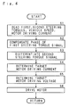
- the control unit 17a reads the first detected signal T1 inputted to the input port a1, second detected signal T2 inputted to the input port a2, detected signal of the vehicle speed V inputted to the input port a4 and current detected signal Is inputted to the input port a5 (S1).
- the phase compensator 171 compensates the phase of the first detected signal T1 inputted through the input port a1 (S2).
- the differentiating unit 175 differentiates the second detected signal T2 inputted through the input port a2 (S3). In consequence, the variation rate of the steering torque is obtained.
- the function generating unit 173 determines the target current I on the basis of the compensated first detected signal T1 and vehicle speed V inputted to the input port a4 (S4). After the target current I is determined, the adder 174a adds the differentiated result of the differentiating unit 175 to the target current I, thereby determining the final control current for driving the motor 8. The subtracter 174b subtracts the current detected signal Is inputted to the input port a5 from the control current. The subtracted result is controlled through PID control by the motor driving circuit 23, and the control voltage of the motor is determined (S5). The motor driving circuit 23 drives the motor 8 with this control voltage (S6), assisting steering force.
- Fig. 7 is a block diagram showing the structure of a modified embodiment of a control system of the power steering apparatus of the invention.
- the same parts are designated by the same reference numerals as in Fig. 4, the description of which is abbreviated here.
- the gain of the first detected signal T1 which is the detected signal of the first torque sensor 21b is set larger than the gain of the second detected signal T2 which is the detected signal of the second torque sensor 22b by adjusting the detecting circuit of the first or second torque sensors 21b or 22b.
- a detected signal of the steering torque is directly inputted to the input port a1 of a control unit 17b from the first torque sensor 21b without passing through an amplifying circuit.
- a detected signal from the second torque sensor 22b which is a sensor to detect the steering torque for the fail-safe purpose mentioned earlier is directly inputted to the input port a2, which is in turn divided into a signal to be differentiated by the differentiating unit 175 and a signal subjected to the fail-safe process.
- the effective detection width of the second detected signal is wider, so that it is possible to control the steering torque in wider range by differentiating the detected signal than the first detected signal T1.
- the final control current of the motor changes immediately, and accordingly the driving force of the motor 8 can be transmitted to the steering mechanism without a delay in responding to the rotation of the steering wheel detected by the torque sensor.
Landscapes
- Engineering & Computer Science (AREA)
- Chemical & Material Sciences (AREA)
- Combustion & Propulsion (AREA)
- Transportation (AREA)
- Mechanical Engineering (AREA)
- Power Steering Mechanism (AREA)
- Steering Control In Accordance With Driving Conditions (AREA)
Claims (2)
- Direction assistée qui comprend:
un capteur de couple (21a,21b) qui détecte un couple de braquage exercé sur un volant;
un moteur (8) pour assister la force de braquage dudit volant; et,
une unité de commande (17a,17b) pour obtenir un courant afin d'entraîner ledit moteur (8) au moyen du réglage d'un premier signal correspondant à un signal du couple de braquage détecté par ledit capteur de couple (21a,21b) avec un second signal obtenu par différentiation dudit signal détecté,
caractérisé en ce que ledit second signal est établi pour qu'il ait une plus grande durée que ledit premier signal dans un intervalle de détection effective qui est l'intervalle entre la limite supérieure et la limite inférieure du couple de braquage où est sorti un signal de tension correspondant à l'amplitude du couple de braquage. - Direction assistée selon la revendication 1, dans laquelle ledit intervalle de détection effective dudit second signal est rendu plus large que celui dudit premier signal en faisant varier le gain pour le signal du couple de braquage détecté par ledit capteur de couple (21a,21b).
Priority Applications (1)
| Application Number | Priority Date | Filing Date | Title |
|---|---|---|---|
| EP93110440A EP0566168B1 (fr) | 1990-05-09 | 1991-05-03 | Direction assistée électrique |
Applications Claiming Priority (4)
| Application Number | Priority Date | Filing Date | Title |
|---|---|---|---|
| JP120344/90 | 1990-05-09 | ||
| JP2120343A JPH0419269A (ja) | 1990-05-09 | 1990-05-09 | 動力舵取装置 |
| JP120343/90 | 1990-05-09 | ||
| JP12034490A JP2873347B2 (ja) | 1990-05-09 | 1990-05-09 | 動力舵取装置 |
Related Child Applications (1)
| Application Number | Title | Priority Date | Filing Date |
|---|---|---|---|
| EP93110440.0 Division-Into | 1991-05-03 |
Publications (3)
| Publication Number | Publication Date |
|---|---|
| EP0460406A2 EP0460406A2 (fr) | 1991-12-11 |
| EP0460406A3 EP0460406A3 (en) | 1992-04-01 |
| EP0460406B1 true EP0460406B1 (fr) | 1994-03-16 |
Family
ID=26457945
Family Applications (2)
| Application Number | Title | Priority Date | Filing Date |
|---|---|---|---|
| EP91107209A Expired - Lifetime EP0460406B1 (fr) | 1990-05-09 | 1991-05-03 | Direction assistée |
| EP93110440A Expired - Lifetime EP0566168B1 (fr) | 1990-05-09 | 1991-05-03 | Direction assistée électrique |
Family Applications After (1)
| Application Number | Title | Priority Date | Filing Date |
|---|---|---|---|
| EP93110440A Expired - Lifetime EP0566168B1 (fr) | 1990-05-09 | 1991-05-03 | Direction assistée électrique |
Country Status (3)
| Country | Link |
|---|---|
| US (1) | US5201818A (fr) |
| EP (2) | EP0460406B1 (fr) |
| DE (2) | DE69101398T2 (fr) |
Families Citing this family (37)
| Publication number | Priority date | Publication date | Assignee | Title |
|---|---|---|---|---|
| JP2981625B2 (ja) * | 1991-07-09 | 1999-11-22 | 光洋精工株式会社 | 動力舵取装置 |
| KR970005786B1 (ko) * | 1992-04-27 | 1997-04-21 | 미쓰비시덴키 가부시키가이샤 | 전동조향 제어장치 |
| US5473539A (en) * | 1992-12-11 | 1995-12-05 | Honda Giken Kogyo Kabushiki Kaisha | Electrically operated power steering apparatus |
| JP2857555B2 (ja) * | 1993-01-27 | 1999-02-17 | 三菱電機株式会社 | 電動式パワーステアリング装置 |
| DE59401651D1 (de) * | 1993-06-02 | 1997-03-06 | Buehler Ag | Schneckenpresse |
| JP2891069B2 (ja) * | 1993-11-18 | 1999-05-17 | 三菱電機株式会社 | 電動式パワーステアリング制御装置 |
| DE4443381C2 (de) * | 1993-12-06 | 2001-11-29 | Honda Motor Co Ltd | Elektrisch betätigte Servolenkvorrichtung |
| JPH07172324A (ja) * | 1993-12-20 | 1995-07-11 | Honda Motor Co Ltd | 電動式パワーステアリング装置 |
| FR2714011B1 (fr) * | 1993-12-22 | 1996-02-02 | Renault | Véhicule automobile à propulsion électrique comportant des moyens d'assistance au changement de direction. |
| JP3212216B2 (ja) * | 1994-03-22 | 2001-09-25 | 三菱電機株式会社 | 直流電動モータ式操舵装置 |
| JP3133896B2 (ja) * | 1994-06-09 | 2001-02-13 | 三菱電機株式会社 | 電動パワーステアリング制御装置 |
| JP2914610B2 (ja) * | 1994-06-28 | 1999-07-05 | 本田技研工業株式会社 | 電動パワーステアリング装置 |
| JP3479730B2 (ja) * | 1994-10-20 | 2003-12-15 | 光洋精工株式会社 | 電動パワーステアリング装置 |
| JPH08282519A (ja) * | 1995-04-10 | 1996-10-29 | Mitsubishi Electric Corp | 電動パワーステアリング装置の制御装置 |
| JP3152339B2 (ja) * | 1995-06-07 | 2001-04-03 | 本田技研工業株式会社 | 電動パワーステアリング装置 |
| JP3519830B2 (ja) * | 1995-09-01 | 2004-04-19 | 三菱電機株式会社 | モータ制御装置 |
| JP3521248B2 (ja) * | 1995-09-08 | 2004-04-19 | 光洋精工株式会社 | 電動パワーステアリング装置 |
| JP3572471B2 (ja) * | 1996-02-21 | 2004-10-06 | 光洋精工株式会社 | 電動パワーステアリング装置 |
| JP3753511B2 (ja) * | 1997-08-27 | 2006-03-08 | 本田技研工業株式会社 | 電動パワーステアリング装置 |
| US6167334A (en) * | 1999-01-05 | 2000-12-26 | Ford Global Technologies, Inc. | Method and apparatus for providing variable assist power steering |
| US6173223B1 (en) | 1999-01-05 | 2001-01-09 | Ford Global Technologies, Inc. | Steering control method for providing variable assist power steering |
| JP4029522B2 (ja) * | 1999-07-02 | 2008-01-09 | 日本精工株式会社 | 電動パワーステアリング装置の制御装置 |
| JP3353770B2 (ja) * | 1999-08-19 | 2002-12-03 | 三菱電機株式会社 | 電動式パワーステアリング制御装置 |
| JP3678097B2 (ja) * | 1999-12-20 | 2005-08-03 | 三菱電機株式会社 | 電動パワーステアリング装置 |
| JP3791663B2 (ja) * | 2000-01-17 | 2006-06-28 | 富士電機ホールディングス株式会社 | 全方向移動車両とその制御方法 |
| JP3847516B2 (ja) * | 2000-03-01 | 2006-11-22 | 三菱電機株式会社 | 電動パワーステアリング制御装置及びその制御方法 |
| JP3777961B2 (ja) * | 2000-09-11 | 2006-05-24 | 日本精工株式会社 | 電動パワーステアリング装置の制御装置 |
| JP4293734B2 (ja) * | 2001-01-17 | 2009-07-08 | 三菱電機株式会社 | 電動式パワーステアリング制御装置 |
| US6662865B2 (en) * | 2001-04-30 | 2003-12-16 | Hewlett-Packard Development Company, L.P. | Multi-load thermal regulating system having electronic valve control |
| DE10336867B4 (de) * | 2003-08-11 | 2021-07-01 | Volkswagen Ag | Fahrzeuglenkung mit elektrischem Hilfsantrieb |
| JP3966274B2 (ja) * | 2003-12-04 | 2007-08-29 | トヨタ自動車株式会社 | 操舵制御装置 |
| DE102004011593B4 (de) * | 2004-03-10 | 2008-04-30 | Audi Ag | Lenkvorrichtung für Kraftfahrzeuge |
| JP4997472B2 (ja) * | 2007-01-09 | 2012-08-08 | 株式会社ジェイテクト | 電動パワーステアリング装置 |
| US7962263B2 (en) * | 2008-04-03 | 2011-06-14 | Cnh America Llc | Adaptive nonlinear steering control system and method for work vehicles |
| KR101022547B1 (ko) * | 2009-04-17 | 2011-03-16 | 현대모비스 주식회사 | 전동 조향 장치의 조향 복원 방법 |
| JP6378887B2 (ja) * | 2014-02-04 | 2018-08-22 | Kyb株式会社 | 電動パワーステアリング装置 |
| CN113492906B (zh) * | 2020-04-03 | 2022-10-25 | 宇通客车股份有限公司 | 一种液压转向系统及其控制方法、装置 |
Family Cites Families (12)
| Publication number | Priority date | Publication date | Assignee | Title |
|---|---|---|---|---|
| JPS6198675A (ja) * | 1984-10-19 | 1986-05-16 | Fuji Heavy Ind Ltd | 電動式パワ−ステアリング装置のモ−タ制御装置 |
| JPS61115771A (ja) * | 1984-11-13 | 1986-06-03 | Fuji Heavy Ind Ltd | 電動式パワステアリング装置の制御装置 |
| JPH0624953B2 (ja) * | 1986-04-08 | 1994-04-06 | 本田技研工業株式会社 | 電動式パワ−ステアリング装置 |
| JPH0662092B2 (ja) * | 1986-04-11 | 1994-08-17 | 本田技研工業株式会社 | 電動式パワ−ステアリング装置 |
| JPS6490870A (en) * | 1987-09-30 | 1989-04-07 | Hitachi Ltd | Motor power steering device |
| JPH01309876A (ja) * | 1988-02-23 | 1989-12-14 | Koyo Seiko Co Ltd | 動力舵取装置 |
| JP2641245B2 (ja) * | 1988-04-14 | 1997-08-13 | 三菱電機株式会社 | 電動式パワーステアリング装置 |
| DE68922248T2 (de) * | 1988-07-11 | 1995-08-31 | Koyo Seiko Co | Motorgetriebene Servolenkung. |
| JPH02256652A (ja) * | 1988-09-05 | 1990-10-17 | Kashima Sekiyu Kk | α―トリフルオロメチル―γ―ニトロ酪酸あるいはそのエステル並びにその製造方法 |
| JPH0285061A (ja) * | 1988-09-20 | 1990-03-26 | Aisin Seiki Co Ltd | 電動パワーステアリング装置のフエイルセイフ装置 |
| US5122958A (en) * | 1989-07-31 | 1992-06-16 | Toyoda Koki Kabushiki Kaisha | Apparatus for controlling steering force produced by power steering system |
| JPH084383Y2 (ja) * | 1989-10-02 | 1996-02-07 | トヨタ自動車株式会社 | 車両用操蛇装置 |
-
1991
- 1991-04-16 US US07/686,107 patent/US5201818A/en not_active Expired - Lifetime
- 1991-05-03 DE DE69101398T patent/DE69101398T2/de not_active Expired - Fee Related
- 1991-05-03 EP EP91107209A patent/EP0460406B1/fr not_active Expired - Lifetime
- 1991-05-03 EP EP93110440A patent/EP0566168B1/fr not_active Expired - Lifetime
- 1991-05-03 DE DE69117194T patent/DE69117194T2/de not_active Expired - Fee Related
Also Published As
| Publication number | Publication date |
|---|---|
| EP0460406A3 (en) | 1992-04-01 |
| EP0566168A3 (en) | 1993-11-18 |
| DE69101398D1 (de) | 1994-04-21 |
| DE69117194D1 (de) | 1996-03-28 |
| EP0566168B1 (fr) | 1996-02-14 |
| DE69101398T2 (de) | 1994-10-20 |
| US5201818A (en) | 1993-04-13 |
| DE69117194T2 (de) | 1996-10-10 |
| EP0460406A2 (fr) | 1991-12-11 |
| EP0566168A2 (fr) | 1993-10-20 |
Similar Documents
| Publication | Publication Date | Title |
|---|---|---|
| EP0460406B1 (fr) | Direction assistée | |
| US5253725A (en) | Power steering apparatus | |
| US5076381A (en) | Power steering apparatus and rotary detector used therefor | |
| US5097918A (en) | Motor-driven power steering apparatus | |
| US6763907B2 (en) | Vehicle steering apparatus | |
| US4961474A (en) | Steering angle middle point detecting apparatus | |
| US4805486A (en) | Locking differential gear assembly | |
| JPH01106776A (ja) | 動力舵取装置 | |
| US20190168800A1 (en) | Ball Nut Assembly For A Power Steering Assembly Of A Vehicle | |
| JP5408472B2 (ja) | 車両用操舵装置 | |
| JP2694213B2 (ja) | 動力舵取装置 | |
| JP2824493B2 (ja) | 動力舵取装置 | |
| JPH0775986B2 (ja) | 動力舵取装置 | |
| JPH0427664A (ja) | 動力舵取装置 | |
| JPH02220969A (ja) | 電動式動力舵取装置 | |
| JP2736413B2 (ja) | 動力舵取装置 | |
| JP3328718B2 (ja) | 動力舵取装置 | |
| JPS6231560A (ja) | 自動車のステアリング装置 | |
| JP2741037B2 (ja) | 動力舵取装置 | |
| JP2580515Y2 (ja) | 電動式舵角付与装置 | |
| JPH0725314B2 (ja) | 舵角中点検出装置 | |
| JP2715107B2 (ja) | 動力舵取装置 | |
| JP2982831B2 (ja) | ステアリング舵角補正装置 | |
| JPH07205822A (ja) | 電動式舵角付与装置 | |
| JPH0624950B2 (ja) | ラツクアンドピニオン型パワ−ステアリング装置 |
Legal Events
| Date | Code | Title | Description |
|---|---|---|---|
| PUAI | Public reference made under article 153(3) epc to a published international application that has entered the european phase |
Free format text: ORIGINAL CODE: 0009012 |
|
| AK | Designated contracting states |
Kind code of ref document: A2 Designated state(s): DE FR GB |
|
| PUAL | Search report despatched |
Free format text: ORIGINAL CODE: 0009013 |
|
| AK | Designated contracting states |
Kind code of ref document: A3 Designated state(s): DE FR GB |
|
| 17P | Request for examination filed |
Effective date: 19920320 |
|
| 17Q | First examination report despatched |
Effective date: 19921005 |
|
| GRAA | (expected) grant |
Free format text: ORIGINAL CODE: 0009210 |
|
| AK | Designated contracting states |
Kind code of ref document: B1 Designated state(s): DE FR GB |
|
| XX | Miscellaneous (additional remarks) |
Free format text: TEILANMELDUNG 93110440.0 EINGEREICHT AM 03/05/91. |
|
| REF | Corresponds to: |
Ref document number: 69101398 Country of ref document: DE Date of ref document: 19940421 |
|
| ET | Fr: translation filed | ||
| PLBE | No opposition filed within time limit |
Free format text: ORIGINAL CODE: 0009261 |
|
| STAA | Information on the status of an ep patent application or granted ep patent |
Free format text: STATUS: NO OPPOSITION FILED WITHIN TIME LIMIT |
|
| 26N | No opposition filed | ||
| REG | Reference to a national code |
Ref country code: GB Ref legal event code: IF02 |
|
| PGFP | Annual fee paid to national office [announced via postgrant information from national office to epo] |
Ref country code: GB Payment date: 20080507 Year of fee payment: 18 |
|
| PGFP | Annual fee paid to national office [announced via postgrant information from national office to epo] |
Ref country code: DE Payment date: 20090429 Year of fee payment: 19 Ref country code: FR Payment date: 20090515 Year of fee payment: 19 |
|
| GBPC | Gb: european patent ceased through non-payment of renewal fee |
Effective date: 20090503 |
|
| PG25 | Lapsed in a contracting state [announced via postgrant information from national office to epo] |
Ref country code: GB Free format text: LAPSE BECAUSE OF NON-PAYMENT OF DUE FEES Effective date: 20090503 |
|
| REG | Reference to a national code |
Ref country code: FR Ref legal event code: ST Effective date: 20110131 |
|
| PG25 | Lapsed in a contracting state [announced via postgrant information from national office to epo] |
Ref country code: DE Free format text: LAPSE BECAUSE OF NON-PAYMENT OF DUE FEES Effective date: 20101201 |
|
| PG25 | Lapsed in a contracting state [announced via postgrant information from national office to epo] |
Ref country code: FR Free format text: LAPSE BECAUSE OF NON-PAYMENT OF DUE FEES Effective date: 20100531 |