EP0460468B1 - Vorrichtung zum automatischen Verbinden von Saumanfang und Saumende eines runden Textilmateriales - Google Patents
Vorrichtung zum automatischen Verbinden von Saumanfang und Saumende eines runden Textilmateriales Download PDFInfo
- Publication number
- EP0460468B1 EP0460468B1 EP91108442A EP91108442A EP0460468B1 EP 0460468 B1 EP0460468 B1 EP 0460468B1 EP 91108442 A EP91108442 A EP 91108442A EP 91108442 A EP91108442 A EP 91108442A EP 0460468 B1 EP0460468 B1 EP 0460468B1
- Authority
- EP
- European Patent Office
- Prior art keywords
- roller
- cloth
- hem
- unit
- final
- Prior art date
- Legal status (The legal status is an assumption and is not a legal conclusion. Google has not performed a legal analysis and makes no representation as to the accuracy of the status listed.)
- Expired - Lifetime
Links
- 239000000463 material Substances 0.000 title claims description 6
- 239000004753 textile Substances 0.000 title claims description 4
- 239000004744 fabric Substances 0.000 claims description 30
- 238000001514 detection method Methods 0.000 claims description 4
- 238000009958 sewing Methods 0.000 claims description 4
- 238000000034 method Methods 0.000 claims description 3
- 230000014759 maintenance of location Effects 0.000 claims description 2
- 238000006073 displacement reaction Methods 0.000 claims 1
- 230000000977 initiatory effect Effects 0.000 claims 1
- 208000032836 Ring chromosome 15 syndrome Diseases 0.000 description 1
- 230000000694 effects Effects 0.000 description 1
- 238000009957 hemming Methods 0.000 description 1
- 230000011664 signaling Effects 0.000 description 1
- 230000001360 synchronised effect Effects 0.000 description 1
Images


Classifications
-
- D—TEXTILES; PAPER
- D05—SEWING; EMBROIDERING; TUFTING
- D05B—SEWING
- D05B33/00—Devices incorporated in sewing machines for supplying or removing the work
Definitions
- Circular cloths requiring such a closed form include fitted bed linen, table cloths and others where the cloth has to cover the object in question with its periphery adapted so that it encloses the the said object laterally.
- the final shape of the cloth, though denominated as circular need not be of that shape but could equally be square, rectangular or any other shape.
- the apparatus, object of this patent has therefore as object the improvement of the machines currently known and employed for this purpose but providing a fully automatic operation to form the hem completely including the final stage of joining up the beginning of the hem with the end, the operation currently carried out by hand and as a further object the providing of detection of misalignment and alignment means ensuring a correct position of the edge of the cloth.
- This present invention patent facilitates therefore the fully automatic forming of the hem in a circular cloth and the detection and alignment of the cloth with an apparatus as described in claim 1.
- the apparatus according to the invention designed to carry out the automatical joining of beginning and end of a hem consists fundamentally of a first guide device, a second device for the first folding and final fold prior to stitching, the two devices being synchronized together with the various sections of the machine in which they are located and which correspond partly to currently known technical means of producing the work indicated herein.
- the guide unit in this present patent has a vertical guide zone consisting of flat plates emprisoning the cloth a guide roller successively and a system of pressure actuated rollers, adjustable at will, to provide the cloth alignment, the position being detected by a system of photo-electric cells, the whole assembly being carried on an arm which is mounted at entry and exit on a shaft which is parallel to the roller so as to provide for the two different positions of the assembly for guiding and feeding.
- the device for first and second folding comprises an arrangement which has as its characteristic a provision for detecting the previously made hem, causing the machine to stop and ejecting the cloth.
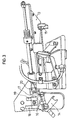
- Figure 1 is a perspective view of the guide and feed unit for the cloth according to this invention.
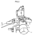
- Figure 2 is a perspective view of the same unit as in figure 1 shown from what is approximately the front part of the feed roller.
- Figures 3 and 4 show respectively the unit for the first and second fold operation which is a part of the apparatus, object of this patent.
- Figure 5 shows a variant of the component for the initial folding.
- the guide and feed unit comprises a main roller -1- made up of two sections -2- and -3- one of which is fixed and the other mobile, this roller receiving the cloth which comes from a guide formed by the plates -4- and -5-, the first of which is fixed while the second can swing on a vertical hinge located on the edge opposite that seen in the figure, these two parts -4- and -5-providing guidance of the cloth which then passes to the roller -1-.
- Photo-electric cells picking up the position of the cloth edge, the orifice -6- show-the position of one of them, cause the alignment of the material.
- the alignment roller -7- acts on the section -2- of the feed roller and the roller -8- acts against the plate -5-, both these rollers being set at a particular angle and coming into operation intermittently to realign the edge of the cloth until it arrives at its correct position.
- the said rotating roller is mounted on a horizontal shaft capable of being acted on by a lower piston and cylinder assembly -9- which can cause an angular movement of roller -1- between the said horizontal and slightly inclined positions.
- a micro-switch -11-, figure 2 In conjunction with the roller -1-, a micro-switch -11-, figure 2, with a mobile arm -12- can operate and detect the entry of the already existing section of hem, signalling to a programmer which can cause the above mentioned changes of alignment which can then allow the operation of joining the beginning and the end of the hem to take place.
- the guide and feed unit operates in conjunction with the first and second fold unit shown in figures 3 and 4 in which may be seen the first fold device -13- and the final fold device -14- of the double articulation type.
- the cloth undergoes its first fold by means of the open ring -15- or by means of a semi-envelopping pre-folding device -21- with a lateral wing -22-, figure 5, then passing to the final folding device -14- which is hinged to a mobile member -16- which in turn can girate on an axis -17-.
- This mobile member -16- is held by two magnets, one being the main magnet -18- and the other the secondary one, -19- with the magnetic strength of magnet -19- being less than that of the magnet -18-, the latter providing the effective retention of the member -16- in its closed position, corresponding to figure 4, that being the position of the normal stitching of the hem.
- the guide device -14- On arrival of the already stitched hem extremity which has to be joined to the other extremity of the hem, the guide device -14- moves outwards as shown in figure 3, operating the micro-switch -20- and thus causing the machine to stop and the cloth to be ejected, this be transmitting a signal to the programmer, causing the plate 5 to swing on its axis to open, and the machine to stop and the roller -1- to descend and allow the ejection of the cloth.
- the above means as indicated permit the machine to operate automatically in joining the beginning to the end of the hem in the so-called circular cloths of textile material.
- the interior of the hem may have within it a cord or elastic as the case may be.
Landscapes
- Engineering & Computer Science (AREA)
- Textile Engineering (AREA)
- Sewing Machines And Sewing (AREA)
- Treatment Of Fiber Materials (AREA)
Claims (6)
- Vorrichtung zum automatischen Verbinden von Anfang und Ende des Saums bei einem kreisförmigen Textilmaterial, die eine Führungs- und Zuführeinheit umfaßt, die mit einer Hauptrolle (1) ausgestattet ist, dadurch gekennzeichnet, daß die Hauptrolle (1) durch einen festen Abschnitt (2) und einen beweglichen Abschnitt (3) gebildet wird, der im Verhältnis zur Horizontalen geneigt werden kann und in einem tragenden Aufbau befestigt ist, der mit dem Arm (9) gekoppelt ist, der seitlich und senkrecht verschiebbar ist, wodurch zwei verschiedene Arbeitspositionen der Einheit gebildet werden, wobei die Einheit eine ebene Eintrittsführung (4,5) aufweist, die aus einer festen Platte (4) und einer beweglichen Platte (5) besteht, die auf einem senkrechten Gelenk beide miteinander schwingen können, wodurch eine Führung für das Gewebe geschaffen wird, ehe es der Rolle (1) zugeführt wird, wobei die Einheit außerdem mit Erfassungssytemen verbunden ist, die mit einer Richtrolle (7), die auf den Abschnitt (2) der Rolle (1) wirkt, und einer Richtrolle (8) gekoppelt sind, die auf die Platte (5) der Führungseinheit wirkt, wodurch bei Bedarf eine automatische Neuausrichtung der Gewebekante hervorgerufen wird.
- Vorrichtung nach Anspruch 1, dadurch gekennzeichnet, daß sie außerdem eine Vorfalteinrichtung (13) und eine Endfalteinrichtung (14) umfaßt, die das Gewebe vor dem Nähen des Saums falten, wobei die Vorfalteinheit (13) in Verbindung mit einem Aufbau aus Kolben und Zylinder arbeitet, der deren Verschiebung verursachen kann, während die Endfalteinrichtung (14) bei der Ankunft des bereits genähten Saumabschnittes bei gleichzeitiger Betätigung eines Mikroschalters (20) entfernbar ist, der den Endzyklus des Verfahrens einleitet, der das Stoppen der Maschine und das Neigen der Rolle (1) umfaßt.
- Vorrichtung nach Anspruch 1, dadurch gekennzeichnet, daß die Richtrolle (7) auf einer Halterung gehalten wird, die variablem Druck von der pneumatischen Einrichtung aus Kolben und Zylinder ausgesetzt ist und eine Neigung aufweist, die durch eine andere Einrichtung aus Kolben und Zylinder eingestellt werden kann, die durch die Anordnung einer photoelektrischen Zelle betätigt wird, die die Position der Gewebekante erfassen kann und bei Bedarf deren Neuausrichtung bewirkt.
- Vorrichtung nach Anspruch 1, dadurch gekennzeichnet, daß es außerdem ein System photoelektrischer Zellen gibt, um die Kante des Materials beim Einfuhren mit der Rolle (8) zur senkrechten Neuausrichtung bezüglich der Ebene der Führungsplatten, die durch eine Öffnung (6) in der festen Platte (4) wirken, mit dem Druck des schwenkbar verbundenen Arms anzuordnen, auf dem sie befestigt ist.
- Vorrichtung nach Anspruch 2, dadurch gekennzeichnet, daß die Endfalteinheit (14) einen Führungsring auf der Gewebekante umfaßt, der an einem Ende auf einem Brükkenteil gegliedert ist, das wiederum am anderen Ende schwenkbar mit dem festen Teil auf der Maschine verbunden und so angeordnet ist, daß es zu einem System aus Dauermagneten (18, 19) entgegengesetzt ist, und das die Endfalteinheit (14) bis zum Zeitpunkt des Eintritts des bereits genahten Saums in ihrer Position halt, wobei sie den Aufbau auf zwei Gelenkachsen schwingen kann, womit der Endfaltring (15) von der Bewegungsbahn des Saums getrennt wird, damit dessen Anfang und Ende automatisch verbunden werden.
- Vorrichtung nach Anspruch 5, dadurch gekennzeichnet, daß einer der Dauermagneten (18), der stärker ist, den gegliederten Aufbau beim Endfalten festhält, während der andere schwächere (19) so gestaltet ist, daß die Rückkehr des gegliederten Aufbaus in seine Arbeitsposition bewirkt wird, nachdem das Fertignähen des Gewebes vorgenommen wurde.
Applications Claiming Priority (2)
| Application Number | Priority Date | Filing Date | Title |
|---|---|---|---|
| ES9001457 | 1990-05-25 | ||
| ES9001457A ES2024810A6 (es) | 1990-05-25 | 1990-05-25 | Procedimiento y su aparato para unir el principio con el final de un dobladillo en una prenda circular textil, de forma automatica. |
Publications (2)
| Publication Number | Publication Date |
|---|---|
| EP0460468A1 EP0460468A1 (de) | 1991-12-11 |
| EP0460468B1 true EP0460468B1 (de) | 1995-09-06 |
Family
ID=8267470
Family Applications (1)
| Application Number | Title | Priority Date | Filing Date |
|---|---|---|---|
| EP91108442A Expired - Lifetime EP0460468B1 (de) | 1990-05-25 | 1991-05-24 | Vorrichtung zum automatischen Verbinden von Saumanfang und Saumende eines runden Textilmateriales |
Country Status (4)
| Country | Link |
|---|---|
| US (1) | US5271347A (de) |
| EP (1) | EP0460468B1 (de) |
| DE (1) | DE69112711T2 (de) |
| ES (2) | ES2024810A6 (de) |
Families Citing this family (13)
| Publication number | Priority date | Publication date | Assignee | Title |
|---|---|---|---|---|
| JPH06304365A (ja) * | 1993-04-21 | 1994-11-01 | Pegasus Sewing Mach Mfg Co Ltd | 筒状生地の自動ヘミング装置 |
| JPH0751476A (ja) * | 1993-08-11 | 1995-02-28 | Morimoto Mfg Co Ltd | シリンダー型ミシン |
| US5622125A (en) * | 1994-09-23 | 1997-04-22 | Union Special Corporation | Automatic coverstitch on circular garment bands |
| US5570647A (en) * | 1994-09-23 | 1996-11-05 | Union Special Corporation | Automatic attachment of a rib knit band to a shirt body |
| US5676078A (en) * | 1994-09-23 | 1997-10-14 | Union Special Corporation | Method and apparatus for sewing sleeves on shirt bodies |
| US5507241A (en) * | 1995-05-08 | 1996-04-16 | Evans; Kenneth H. W. | Cap driver for embroidery machine |
| US5622128A (en) * | 1995-10-20 | 1997-04-22 | Jet Sew Technologies, Inc. | Fabric tensioning system and separator plate for automated sewing machine |
| US5622129A (en) * | 1995-10-20 | 1997-04-22 | Jet Sew Technologies, Inc. | Pneumatic tensioning arm for automated sewing machine |
| US5899159A (en) * | 1997-12-02 | 1999-05-04 | Atlanta Attachment Company | Method of forming a folded hem and system for guiding a multiple ply seam of a textile work piece |
| US6295940B1 (en) * | 1998-06-22 | 2001-10-02 | Sew-Fine, Llc | System and method for processing workpieces |
| US6295481B1 (en) | 1999-03-24 | 2001-09-25 | Ecp Family Properties | Serial bus control system for sewing equipment |
| US6401641B1 (en) * | 2000-05-10 | 2002-06-11 | Toshiharu Tom Miyano | Apparatus and method for producing a pattern on a piece of material |
| CN109137278B (zh) * | 2018-08-16 | 2020-07-17 | 宋任菊 | 一种具有自动裁剪缝合功能的皮带圈制作装置 |
Family Cites Families (10)
| Publication number | Priority date | Publication date | Assignee | Title |
|---|---|---|---|---|
| GB1349350A (en) * | 1970-06-18 | 1974-04-03 | Nat Res Dev | Guiding apparatus for a sewing machine |
| US3865058A (en) * | 1973-05-30 | 1975-02-11 | Automatech Ind | Method and apparatus for forming and joining hems, particularly on tubular articles |
| US3890911A (en) * | 1974-04-11 | 1975-06-24 | Usm Corp | Automatic hemming machine |
| JPS5232749A (en) * | 1975-09-05 | 1977-03-12 | Yamato Sewing Machine Mfg | Method and device for mechanically hemming annular clothes at bottom |
| DE3125125C2 (de) * | 1981-06-26 | 1985-05-09 | Union Special Gmbh, 7000 Stuttgart | Spanneinrichtung für Nähmaschinen |
| ES8104713A1 (es) * | 1979-12-12 | 1981-05-16 | Carreras Fontcubierta Francisc | Procedimiento para insertar un elemento elastico en zonas predeterminadas de un articulo textil confeccionado |
| FR2521604A1 (fr) * | 1982-02-12 | 1983-08-19 | Amf Inc | Dispositif pour l'execution automatique des ourlets aux extremites libres des parties tubulaires des vetements |
| US4665848A (en) * | 1984-02-13 | 1987-05-19 | Levi Strauss & Co. | Method and apparatus for automatically hemming garments |
| EP0177149B1 (de) * | 1984-08-21 | 1989-03-15 | Pegasus Sewing Machine Mfg. Co., Ltd. | Saumvorrichtung |
| JPS6472790A (en) * | 1987-09-12 | 1989-03-17 | Hamusu Kk | Mechnism for rolling three times cuffs of trousers |
-
1990
- 1990-05-25 ES ES9001457A patent/ES2024810A6/es not_active Expired - Lifetime
-
1991
- 1991-05-21 US US07/703,388 patent/US5271347A/en not_active Expired - Fee Related
- 1991-05-24 ES ES91108442T patent/ES2080187T3/es not_active Expired - Lifetime
- 1991-05-24 EP EP91108442A patent/EP0460468B1/de not_active Expired - Lifetime
- 1991-05-24 DE DE69112711T patent/DE69112711T2/de not_active Expired - Fee Related
Also Published As
| Publication number | Publication date |
|---|---|
| ES2080187T3 (es) | 1996-02-01 |
| EP0460468A1 (de) | 1991-12-11 |
| DE69112711D1 (de) | 1995-10-12 |
| ES2024810A6 (es) | 1992-03-01 |
| US5271347A (en) | 1993-12-21 |
| DE69112711T2 (de) | 1997-06-19 |
Similar Documents
| Publication | Publication Date | Title |
|---|---|---|
| EP0460468B1 (de) | Vorrichtung zum automatischen Verbinden von Saumanfang und Saumende eines runden Textilmateriales | |
| US5108017A (en) | Sleeve flip over device | |
| US5033399A (en) | Automatic fabric guide in sewing machine | |
| US3886879A (en) | Shirt front assembly, method and apparatus | |
| US3865058A (en) | Method and apparatus for forming and joining hems, particularly on tubular articles | |
| US3898941A (en) | Apparatus for manufacturing and stacking hemmed fabric pieces | |
| US5709162A (en) | Semi-automatic method to attach circular collars to T-shirts | |
| US4434731A (en) | Arrangement for sewing separate successive seams along different directions in a fabric material | |
| US5079867A (en) | Ironer-folder for flatwork, apparatus and method | |
| US4484532A (en) | Apparatus for blind stitching an S-shaped hem | |
| GB2175618A (en) | Method and apparatus for sewing workpieces | |
| US4100864A (en) | Automatic work guidance mechanism | |
| BR102012012045A2 (pt) | Dispositivo de prensa acoplável com uma máquina de costura, máquina de costura e método para costura de um tecido de espessura variável | |
| US3469545A (en) | Conveyor sewing unit with shiftable top feed belt and work loading arrangement | |
| US4665848A (en) | Method and apparatus for automatically hemming garments | |
| JPH08309059A (ja) | スリーブ製造方法及びスリーブ製造装置 | |
| GB1349350A (en) | Guiding apparatus for a sewing machine | |
| US5628264A (en) | Sleeve making method and apparatus | |
| US4719863A (en) | Small cloth vise for a sewing machine | |
| JPS59232576A (ja) | シヤツのカフス製造設備 | |
| US4474637A (en) | Labeling machine and label | |
| KR100876706B1 (ko) | 테두리 장식용 재봉틀의 주머니 천 공급장치 | |
| US5622129A (en) | Pneumatic tensioning arm for automated sewing machine | |
| US3834331A (en) | Machine for automatic assembly of knitted articles | |
| US5931108A (en) | Process and automatic sewing machine for sewing a flap with a rough closing edge and a pocket on a fabric part in one operation |
Legal Events
| Date | Code | Title | Description |
|---|---|---|---|
| PUAI | Public reference made under article 153(3) epc to a published international application that has entered the european phase |
Free format text: ORIGINAL CODE: 0009012 |
|
| AK | Designated contracting states |
Kind code of ref document: A1 Designated state(s): DE ES FR GB IT |
|
| 17P | Request for examination filed |
Effective date: 19920602 |
|
| EL | Fr: translation of claims filed | ||
| 17Q | First examination report despatched |
Effective date: 19930721 |
|
| GRAA | (expected) grant |
Free format text: ORIGINAL CODE: 0009210 |
|
| AK | Designated contracting states |
Kind code of ref document: B1 Designated state(s): DE ES FR GB IT |
|
| REF | Corresponds to: |
Ref document number: 69112711 Country of ref document: DE Date of ref document: 19951012 |
|
| ITF | It: translation for a ep patent filed | ||
| ET | Fr: translation filed | ||
| RAP2 | Party data changed (patent owner data changed or rights of a patent transferred) |
Owner name: TEXPA-ARBTER MASCHINENBAUGESELLSCHAFT MBH |
|
| RIN2 | Information on inventor provided after grant (corrected) |
Free format text: CARRERAS FONTCUBERTA, FRANCISCO |
|
| REG | Reference to a national code |
Ref country code: ES Ref legal event code: FG2A Ref document number: 2080187 Country of ref document: ES Kind code of ref document: T3 |
|
| ITPR | It: changes in ownership of a european patent |
Owner name: CESSIONE EPO;TEXPA-ARBTER MASCHINENBAUGESELLSCHAFT |
|
| PLBE | No opposition filed within time limit |
Free format text: ORIGINAL CODE: 0009261 |
|
| STAA | Information on the status of an ep patent application or granted ep patent |
Free format text: STATUS: NO OPPOSITION FILED WITHIN TIME LIMIT |
|
| 26N | No opposition filed | ||
| PGFP | Annual fee paid to national office [announced via postgrant information from national office to epo] |
Ref country code: GB Payment date: 19980225 Year of fee payment: 8 |
|
| PGFP | Annual fee paid to national office [announced via postgrant information from national office to epo] |
Ref country code: FR Payment date: 19980226 Year of fee payment: 8 |
|
| PGFP | Annual fee paid to national office [announced via postgrant information from national office to epo] |
Ref country code: ES Payment date: 19980526 Year of fee payment: 8 |
|
| PG25 | Lapsed in a contracting state [announced via postgrant information from national office to epo] |
Ref country code: GB Free format text: LAPSE BECAUSE OF NON-PAYMENT OF DUE FEES Effective date: 19990524 |
|
| PG25 | Lapsed in a contracting state [announced via postgrant information from national office to epo] |
Ref country code: ES Free format text: LAPSE BECAUSE OF NON-PAYMENT OF DUE FEES Effective date: 19990525 |
|
| GBPC | Gb: european patent ceased through non-payment of renewal fee |
Effective date: 19990524 |
|
| PG25 | Lapsed in a contracting state [announced via postgrant information from national office to epo] |
Ref country code: FR Free format text: LAPSE BECAUSE OF NON-PAYMENT OF DUE FEES Effective date: 20000131 |
|
| REG | Reference to a national code |
Ref country code: FR Ref legal event code: ST |
|
| REG | Reference to a national code |
Ref country code: ES Ref legal event code: FD2A Effective date: 20010503 |
|
| PGFP | Annual fee paid to national office [announced via postgrant information from national office to epo] |
Ref country code: DE Payment date: 20010727 Year of fee payment: 11 |
|
| PG25 | Lapsed in a contracting state [announced via postgrant information from national office to epo] |
Ref country code: DE Free format text: LAPSE BECAUSE OF NON-PAYMENT OF DUE FEES Effective date: 20021203 |
|
| PG25 | Lapsed in a contracting state [announced via postgrant information from national office to epo] |
Ref country code: IT Free format text: LAPSE BECAUSE OF NON-PAYMENT OF DUE FEES;WARNING: LAPSES OF ITALIAN PATENTS WITH EFFECTIVE DATE BEFORE 2007 MAY HAVE OCCURRED AT ANY TIME BEFORE 2007. THE CORRECT EFFECTIVE DATE MAY BE DIFFERENT FROM THE ONE RECORDED. Effective date: 20050524 |