EP0462571B1 - Anordnung von Lautsprechern im Gehäuse eines Fernsehempfängers - Google Patents
Anordnung von Lautsprechern im Gehäuse eines Fernsehempfängers Download PDFInfo
- Publication number
- EP0462571B1 EP0462571B1 EP91109983A EP91109983A EP0462571B1 EP 0462571 B1 EP0462571 B1 EP 0462571B1 EP 91109983 A EP91109983 A EP 91109983A EP 91109983 A EP91109983 A EP 91109983A EP 0462571 B1 EP0462571 B1 EP 0462571B1
- Authority
- EP
- European Patent Office
- Prior art keywords
- horn
- cabinet
- speaker
- loudspeaker arrangement
- baffle board
- Prior art date
- Legal status (The legal status is an assumption and is not a legal conclusion. Google has not performed a legal analysis and makes no representation as to the accuracy of the status listed.)
- Expired - Lifetime
Links
Images


Classifications
-
- H—ELECTRICITY
- H04—ELECTRIC COMMUNICATION TECHNIQUE
- H04R—LOUDSPEAKERS, MICROPHONES, GRAMOPHONE PICK-UPS OR LIKE ACOUSTIC ELECTROMECHANICAL TRANSDUCERS; ELECTRIC HEARING AIDS; PUBLIC ADDRESS SYSTEMS
- H04R5/00—Stereophonic arrangements
- H04R5/02—Spatial or constructional arrangements of loudspeakers
-
- H—ELECTRICITY
- H04—ELECTRIC COMMUNICATION TECHNIQUE
- H04N—PICTORIAL COMMUNICATION, e.g. TELEVISION
- H04N5/00—Details of television systems
- H04N5/64—Constructional details of receivers, e.g. cabinets or dust covers
-
- H—ELECTRICITY
- H04—ELECTRIC COMMUNICATION TECHNIQUE
- H04N—PICTORIAL COMMUNICATION, e.g. TELEVISION
- H04N5/00—Details of television systems
- H04N5/64—Constructional details of receivers, e.g. cabinets or dust covers
- H04N5/642—Disposition of sound reproducers
-
- H—ELECTRICITY
- H04—ELECTRIC COMMUNICATION TECHNIQUE
- H04R—LOUDSPEAKERS, MICROPHONES, GRAMOPHONE PICK-UPS OR LIKE ACOUSTIC ELECTROMECHANICAL TRANSDUCERS; ELECTRIC HEARING AIDS; PUBLIC ADDRESS SYSTEMS
- H04R1/00—Details of transducers, loudspeakers or microphones
- H04R1/20—Arrangements for obtaining desired frequency or directional characteristics
- H04R1/22—Arrangements for obtaining desired frequency or directional characteristics for obtaining desired frequency characteristic only
- H04R1/30—Combinations of transducers with horns, e.g. with mechanical matching means, i.e. front-loaded horns
-
- H—ELECTRICITY
- H04—ELECTRIC COMMUNICATION TECHNIQUE
- H04R—LOUDSPEAKERS, MICROPHONES, GRAMOPHONE PICK-UPS OR LIKE ACOUSTIC ELECTROMECHANICAL TRANSDUCERS; ELECTRIC HEARING AIDS; PUBLIC ADDRESS SYSTEMS
- H04R2499/00—Aspects covered by H04R or H04S not otherwise provided for in their subgroups
- H04R2499/10—General applications
- H04R2499/15—Transducers incorporated in visual displaying devices, e.g. televisions, computer displays, laptops
Definitions
- the present invention relates to a loudspeaker arrangement in a television receiver cabinet, and in particular, it is concerned with a horn sub-assembly simple in structure but excellent in sound performance. In another aspect of the present invention, it is particularly concerned with a loudspeaker arrangement in a television receiver cabinet of a space-effective type.
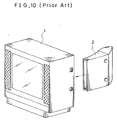
- the conventional loudspeaker horn of this type for the television receiver has been realized, for instance, by forming a speaker horn sub-assembly 2 as shown in FIG.10, independently from the cabinet 1 of the television receiver and then by installing it in the cabinet.
- the conventional speaker horn sub-assembly is structured by forming a front horn so that it may project from a front face side of a baffle board for supporting the speaker unit and by forming a rear horn so that it may project from a rear face side of the baffle board.
- the front horn should be configurated to have a narrowed cross-section region at its front half and a small width sound outlet at its front end lest it should collide with a cathode ray tube.
- the stated structure of the horn sub-assembly is however disadvantageous in that the cabinet of the television receiver must be provided with a supporting means (omitted from the illustration) for the sub-assembly, and that an additional space must be provided in the cabinet to be occupied by the supporting means rather than by the horn sub-assembly itself.
- Another disadvantage inherent to the conventional structure is a stringent spatial limitation imposed on the interior space of the television receiver cabinet which must contain a cathode ray tube, and an additional problem is another limitation imposed on the configuration of the horn sub-assembly for making it in conformity with that of the cabinet and thus the expected sound performance is not satisfactory.
- each of the speaker horn sub-assemblies may include a front horn, which is projected forwards from a baffle board for supporting a speaker unit and has a narrowed cross-section region.
- Each of the mid-point between side members of said front horns at said narrowed cross-section region may preferably in a plane which includes each of the center lines of the speaker units, and each of said front horn may preferably be formed.
- Both side members at regions between said baffle board and said narrowed cross-section regions are preferably and substantially symmetrical with respect to a plane which contains the center lines of said speaker units and is perpendicular to the planes of the baffle boards.
- each of the baffle boards for supporting said speaker units may preferably be provided on each of the side members of said cabinet in planes independent from said cabinet.
- Each of said speaker horn sub-assemblies may be constituted by including, as their essential components, each of the parts of the side members of said cabinet in its original place.
- Each of said baffle boards may preferably be positioned at an angle greater than 0° and smaller than 45° with respect to the front face of said television receiver.
- each of said horn sub-assemblies may also be comprised of a baffle board with an opening for supporting a speaker unit, a front horn and a rear horn. Side of the horn which faces said side wall member of said cabinet is cut open; and preferably, the baffle board, top member, bottom member and a side member opposite to said side may be integrally formed, and each of said horn sub-assemblies may be fixed on said side wall member of said television cabinet so that its open cut side face may closely contact with said side wall member.
- each of said speaker horn sub-assemblies may be formed by combining a side member opposite to the side facing the side wall member of said cabinet, a baffle board with an opening for supporting a speaker unit, a top member and a bottom member, and a part of the side wall member of said television receiver cabinet in an integral body. It is preferable that distances between the baffle board and a sound outlet of said horn sub-assembly, both along said part of the wall member of the cabinet and along said side member of the horn sub-assembly opposite to the side facing to the side member of said cabinet, may be substantially equal.
- each of said speaker horn sub-assemblies may comprise a front horn, a rear horn and a baffle board with an opening for supporting a speaker unit, and an open cut face in the same direction as that of said front horns may also be preferably provided on each of said rear horns.
- said open cut face provided on said rear horn may preferably be in a plane substantially equal to that of the open cut face of said front horn, and above and below said open cut face of said front horn.
- Each of the areas of the open cut faces provided on said rear horns may preferably be substantially equal to each of the areas of the open cut faces of said front horns.
- each of the areas of the upper and lower open cut faces of said front horns may preferably be substantially equal to each of the areas of the open cut faces provided on the upper and lower parts of said rear horns.
- each of said speaker horn sub-assemblies may comprise a front horn, a rear horn and a baffle board with an opening for supporting a speaker unit.
- Each of the areas of the front open outlets of said front horns may preferably be substantially equal to each of the areas of parts of said baffle boards actually utilized for supporting the speaker unit.
- the loudspeaker arrangement may further comprise at least one sound reflector in or on each of said speaker horn sub-assemblies.
- the sound reflector may preferably be formed on the front horn of each of said speaker horn sub-assemblies, and may be either one of a dent or a protrusion provided on each of the lids covering open cut faces or side wall members of said receiver cabinet as an integral component of said horn sub-assemblies. Or alternatively, the sound reflector may be attached inside the side wall member of said receiver cabinet which corresponds to said front horn.
- the loudspeaker arrangement may further comprise at least one bass-reflex port on each of said speaker horn sub-assemblies.
- Said bass-reflex port may preferably be provided on the rear horn of each of said speaker horn sub-assemblies, and may preferably be formed as an opening provided on each of the lids or side wall members of said receiver cabinet as an integral component of said speaker horn sub-assemblies.
- both of the side faces of said speaker horn sub-assemblies may be cut open, and each of said cut open faces may preferably be covered with a lid having, at its front part, at least one cramp means for securing engagement with top plate member or bottom plate member of the front horn part of said speaker horn sub-assembly.
- a pair of woofer speakers may preferably be laterally provided on said baffle side by side, and said front horn is partitioned into a pair of branch horns each of which corresponds to each of said woofers.
- a woofer speaker and a partitioned front horn part having at least three branch horns may preferably be provided on the baffle board with said woofer at its center, and two tweeter speakers are provided on each of the branch horns of both sides.
- said rear closed space if any, may preferably be sealed air-tightly.
- the loudspeaker arrangement built in accordance with the present invention provides the speaker horn sub-assembly of the television receiver to be formed together with its cabinet by utilizing the top or side wall member of the cabinet in its original place, only little limitation is imposed on the space being occupied by the horn sub-assembly. Further, since a substantially equalized sound balance is obtained between the right and left loudspeakers, an improved sound performance is obtained.
- a space effective design of the television receiver cabinet with small width is made possible.
- a stereophonic sound system or a split band sound system can be realized by partitioning the front horn into a plurality of branch horns and by utilizing some of the branch horns for a means with a bass-reflex port.
- a television receiver cabinet 10 takes a two piece structure, which is composed of a rear cabinet 11 and a front cabinet 31.
- a pair of dents 14 and 15 formed by, for instance, depressing a sheet-like material of the wall members.
- Each of the dents 14 and 15 is composed of a U-cross-section channel 16 or 17 and a baffle board 18 or 19, which is disposed in a plane of the front face of the rear cabinet 11 and supports a speaker unit 20 or 21.
- each of the baffle boards 18 and 19 there are provided an opening 22 or 23 for the speaker units 20 or 21 and (threaded) holes 24 or 25 for fixing the speaker unit on the battle board 18 or 19.
- each of the U-cross-section channels 16 and 17 forms rear horn of the speaker horn sub-assembly, respectively.
- the U-cross-section channels 16 and 17 are extended forwards beyond the front face of the rear cabinet 11 up to an escutcheon 30, as elongated U-cross-section channels 32 and 33.
- the elongated channels 32 and 33 have their open-cut sides facing the side wall members 34 and 35 of the front cabinet 31, respectively, and when combined with the front cabinet 31, form front horns of the horn sub-assemblies.
- an inner horn structure composed of a pair of wall member 36 and 37 is provided in each of the front horns.
- the lids 28 and 29 optionally have their forwardly elongated members 38 and 39, respectively as shown in FIG. 1(d) for covering the open-cut sides of the elongated channels 32 and 33.
- any pieces 40 of suitable sound absorbing material may be provided on any appropriate places, for instance, in the interstices formed between the inner horn members 36 and 37, and top and bottom wall members 32 or 33.
- any gasket 41 or elastic packing material made of, for example, polyurethane foam may be used in assembling the respective member into a combined body as shown in FIG.1 (c).
- another mode of television receiver cabinet 110 also takes a two piece structure composed of a rear cabinet 111 and a front cabinet 131.
- a pair of rear horns 114 and 115 of the speaker horn sub-assemblies composed of U-cross-section channels and parts of the side wall members 112 and 113 of the rear cabinet 111.
- both sides of the front cabinet 131 there are provided a pair of front horns 132 and 133 composed of channels and parts of the side wall members 134 and 135 whose U-cross-sections at the rear face of the front cabinet 131, i.e., the front face of the rear cabinet 111, are substantially equal to those of the channels 114 and 115, respectively.
- an escutcheon 130 is fixed in front of the front cabinet 131.
- baffle boards Being interposed between the rear cabinet 111 and the front cabinet 131 and at positions which correspond to the U-cross-section channels, there are a pair of baffle boards (only the left side thereof 118 is illustrated). In the baffle board 118, there are provided an opening 122 for mounting the speaker unit 120 thereon and threaded holes 124 for securing the speaker unit on the boards.
- FIG.3(a) Another cabinet 201 of the embodiment shown in a half cross-sectional plane view of FIG.3(a) takes a one-piece structure of a polygon. Since this structure is also symmetrical with respect to a vertical plane which includes the center-line of the cathode ray tube CRT 99, only left side half thereof is cut out for illustration and will be described.
- baffle boards 218 with an opening 222 for mounting a speaker unit 220 thereto is fixed to the side wall member 213 of the cabinet 211 along a plane which crosses the plane of the side wall member 213.
- Both of top and bottom members 211 and 212 are also fixed to the side wall member 213 of the cabinet 201 in parallel with the top and bottom wall member of the cabinet 201 to form a U-cross-section channel as a shelf hung on the inner side wall of the cabinet 201.
- the open-cut side of the channel is covered with a flexed plate member 214 to form a speaker horn sub-assembly having a rear horn 215 and a front horn 232, which has a narrowed cross-section region 235 towards the front end thereof, i.e., a sound outlet 236, lest it should collide with the CRT.
- a mid point P between the side wall member 213 of the cabinet 201 and the flexed plate member 214, in a vertical plane Q at which the cross-section of the front horn 232 begins to narrow is in a vertical plane which includes the center-line O -- P of the speaker unit and the center-line P -- O' of the region 235.
- a distance between the plane of the baffle board 218 and the plane Q along the side wall member 213 is substantially equal to the distance between the plane of the baffle board 218 and the plane Q along the flexed plate member 214.
- a part of the front horn 232 between the baffle board 218 and the plane Q is substantially symmetrical with respect to the plane including the center line of the speaker unit 220.
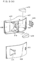
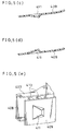
- FIG. 4(a) Another cabinet 301 of one piece structure is also symmetrical with respect to a vertical plane including the center line of the cathode ray tube CRT, and is shown in a partly cross-sectional plane view of FIG. 4(a).
- FIG.4(a) only a left side half-finished speaker horn sub-assembly and a left half of the CRT are shown in cross-section.
- FIG.4(b) is a front perspective view
- FIG.4(c) is a rear perspective view of one of the half-finished speaker horn sub-assembly 302.
- the sub-assembly 302 is half-finished beforehand by combining members for structuring a front horn 332, a rear horn 313, a baffle board 318 with an opening 322 and threaded holes 324 for supporting a speaker unit 320 and a fastening means 338.
- the half-finished sub-assembly 302 serves to act as the speaker horn sub-assembly together with a part of the side wall member 313 of the cabinet 301. In this case however the rear horn 313 is closed air-tightly.
- FIG.4(a) also shows that a mid point P at the narrowed cross-section region 335 of the front horn 332, in a vertical plane Q, is in a vertical plane which includes the center-line 0 - 0' of the speaker unit, and that distances between the plane of the baffle board 318 and the plane Q, both along the side members are substantially equal.
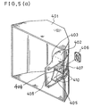
- the receiver cabinet takes a two-piece structure again, wherein only a rear cabinet 401 and a right side horn sub-assembly are illustrated.
- Two U-cross-section channels 402 and 403 are joined at a baffle board 404 with an opening 405 for mounting a speaker unit 406 thereon.
- the thus combined channels 402 and 403 as well as the baffle board 404 compose a half-unit of the speaker horn sub-assembly whose side face is cut open in both regions of a rear horn 407 and a front horn 408.
- the half-unit is finished to the horn sub-assembly when open-cut faces are covered with a lid 409.
- a pair of inner horn members 410 are provided in the front horn 408 and a sound reflector 411 is provided on the lid 409.
- a pair of sound absorbers 420 made of elastic material are also provided behind the inner horn members 410.
- the sound reflector 411 is an inwardly protruded dent of the lid 409. If the front horn 408 is constituted with a part of the side wall member of the front cabinet as in the case of Example 1, the sound reflector 411 is provided in the interior of the front cabinet.
- the lid 409 is further provided with clamp means 413, made of resilient material, for instance metal spring, for engaging the front horn 408 for easy assembling.
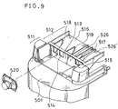
- FIG.6(a) schematically shows a general concept of a series of embodiments built in accordance with the stated another aspect of the present invention.
- FIG.6(b) is a side sectional view of the upper half of the television receiver 500 having the speaker sub-assembly 510 of this type. In both the figures.
- FIG.6(a) a television receiver 500 whose top is hypothetically depicted to be transparent.
- the speaker horn sub-assembly 510 takes a flexed two-piece structure composed of a rear closed space 511 and a front horn 512.
- the rear closed space 511 is mounted on a rear cabinet 501 of the television receiver 500, and the front horn 512 is inserted into a front cabinet 502 to be contained in a dome 503 ingtegrally formed on top of the front cabinet 502, when being assembled.
- a pair of inner horn members 518 and 519 are also provided in the branch horn 516 as more illustratively shown by FIG.6(c), wherein only the sub-assembly is viewed from the rear side and a mode of partitioning is differently depicted, and the opening 514 is split into two, while their functions are substantially the same.
- FIG.6(d) The mode of the assembling process is depicted in an exploded perspective view of FIG.6(d) with a variation of the embodiment shown in FIGs.6(a), 6(b) and 6(c).
- a woofer speaker 521 and a tweeter speaker 522 are provided instead of a single speaker unit, and the front horn 512 is partitioned into three branch horns 516, 517 and 526, of which the center branch horn 526 serves as a means with bass-reflex port.
- a pair of inner horn members 518 and 519 as well as a pair of sound absorbing means 527 and 528 are also contained, in order to expand the reproducible frequency band in a two-way sound system.
- the upper face of the speaker horn sub-assembly 510 is covered with a lid 504 having a pair of sound reflectors 533 corresponding to the pair of the branch horns 516 and 517 and formed as dents on the lid 504.
- a pair of speaker units 523 and 524 are fixed on the baffle board 513 of the embodiment illustrated with reference to FIG.6 for realizing a stereophonic sound performance.
- a pair of inner horn members 518 and 519 are also provided in each of the branch horns 516 and 517.
- the front horn 512 is partitioned into three branch horns 516, 517 and 526, of which the center branch horn 517 has a pair of inner horn members 518 and 519.
- a woofer speaker 521 is provided at a position corresponding to the center branch horn 517 of the the baffle board 513 which is similar to that illustrated in FIG.6(a).
- a pair of tweeter speakers 522 are provided on the baffle board 513 at positions corresponding to the side branch horns 516 and 526. Thereby a stereophonic sound performance in a two-way sound system is realized.
- the front horn 512 which is projected from a baffle board 513 of the embodiment similar to that illustrated in FIG.6(a), is partitioned into four branch horns 516, 517, 526 and 526', of which those 526 and 526' are used as vacant spaces for avoiding sound interference.
Landscapes
- Engineering & Computer Science (AREA)
- Signal Processing (AREA)
- Physics & Mathematics (AREA)
- Acoustics & Sound (AREA)
- Multimedia (AREA)
- Health & Medical Sciences (AREA)
- Otolaryngology (AREA)
- Details Of Audible-Bandwidth Transducers (AREA)
- Obtaining Desirable Characteristics In Audible-Bandwidth Transducers (AREA)
- Telephone Set Structure (AREA)
Claims (30)
- Lautsprecheranordnung in einem Fernsehempfängergehäuse (10) mit einer Mehrzahl von Wandteilen, wobei die Lautsprecheranordnung wenigstens eine Lautsprecherhornbaugruppe aufweist, wobei jede der Lautsprecherhornbaugruppen wenigstens eine Lautsprechereinheit (20, 21) und eine Hornstruktur aufweist,
dadurch gekennzeichnet, daßdie Hornstruktur ein vorderes Horn (32, 33), ein hinteres Horn (16, 17) und eine Schallwandplatte (18, 19) zum Anbringen der Lautsprechereinheit (20, 21) daran und zum Trennen des hinteren Horns vom vorderen Horn aufweist,wenigstens ein Abschnitt der Wandteile (12, 13, 34, 35) einen Bestandteil der Lautsprecherhornbaugruppe bildet,das Fernsehempfängergehäuse (10) eine zweiteilige Struktur mit einem vorderen Gehäuse (31) und einem hinteren Gehäuse (11) aufweist,das hintere Gehäuse (11) an beiden Seitenwandteilen (12, 13) ein Paar von Ausbuchtungen aufweist, die jeweils aus einem Kanal (16, 17) U-förmigen Querschnitts bestehen, wobei die Schallwandplatte (18, 19) eine Öffnung (22, 23) zum Anbringen der Lautsprechereinheit (20, 21) daran in einer Ebene der Vorderseite des hinteren Gehäuses (11) aufweist, dessen hinteres offenes Ende durch einen Deckel (28, 29) abgedeckt ist, um das hintere Horn (16, 17) der Lautsprecherhornbaugruppe abzudecken, undjeder der Kanäle U-förmigen Querschnitts nach vorne über die Vorderseite des hinteren Gehäuses (11) hinaus verlängert ist, um das vordere Horn (32, 33) mit einem Teil des Seitenwandteils (34, 35) des vorderen Gehäuses (31) zu bilden, wenn es mit dem vorderen Gehäuse verbunden ist. - Lautsprecheranordnung nach Anspruch 1, wobeidie Schallwandplatte (18, 19) die Lautsprechereinheit (20, 21) trägt und einen verengten Querschnittsbereich aufweist,jeder Mittelpunkt zwischen Seitenteilen des vorderen Horns (31) im verengten Querschnittsbereich in einer Ebene liegt, die jede der Mittenlinien der Lautsprechereinheit (20, 21) enthält, unddas vordere Horn (32, 33) in einer Weise gebildet ist, daß seine beiden Seitenteile in Bereichen zwischen der Schallwandplatte (18, 19) und den Bereichen verengten Querschnitts im wesentlichen symmetrisch in Bezug auf eine Ebene sind, die jede der Mittenlinien der Lautsprechereinheit (20, 21) enthält, und senkrecht zu der Ebene der Schallwandplatte (18, 19) verläuft.
- Lautsprecheranordnung nach Anspruch 1, wobeidie Schallwandplatte (18, 19) integral mit Abschnitten der Seitenwandteile (12, 13) gebildet und auf Seitenteilen eines hinteren Gehäuses (11) in Ebenen unabhängig von diesem Gehäuse vorgesehen ist, unddie Schallwandplatte (18, 19) unter einem Winkel größer 0° und kleiner 45° in Bezug auf die Vorderseite des Fernsehempfängers (10) angeordnet ist.
- Lautsprecheranordnung nach Anspruch 1, wobeidie Schallwandplatte (18, 19) eine Öffnung zum Anbringen der Lautsprechereinheit (20, 21) daran aufweist, wobei eine Seite jeder der Hornbaugruppen, die dem Seitenwandteil (12, 13, 34, 35) des Gehäuses (10) gegenüberliegt, freigeschnitten ist, und die Schallwandplatte (18, 19), das obere Teil, das untere Teil und ein Seitenteil gegenüberliegend zu der Seite, die dem Seitenwandteil des Gehäuses gegenüberliegt, integral gebildet sind, undjede der Hornbaugruppen an dem Seitenwandteil (12, 13, 34, 35) des Fernsehempfängergehäuses so befestigt ist, daß seine freigeschnittene Seitenfläche in engem Kontakt mit dem Seitenwandteil des Gehäuses gelangen kann.
- Lautsprecheranordnung nach Anspruch 1, wobeijede der Lautsprecherhornbaugruppen durch Verbinden eines Seitenteils gegenüber der Seite, die dem Seitenwandteil des Gehäuses gegenüberliegt, der Schallwandplatte (18, 19) mit einer Öffnung (22, 23) zum Aufnehmen einer Lautsprechereinheit (20, 21) daran, eines oberen Teils und eines unteren Teils und eines Abschnitts des Seitenwandteils des Fernsehempfängergehäuses in einen integralen Körper miteinander gebildet ist, unddie Abstände zwischen der Schallwandplatte (18, 19) und einem Schallauslaß der Hornbaugruppe sowohl entlang dem Abschnitt des Wandteils des Gehäuses sowie entlang dem Seitenteil der Hornbaugruppe gegenüber der Seite, die dem Seitenwandteil des Gehäuses gegenüberliegt, im wesentlichen gleich sind.
- Lautsprecheranordnung nach Anspruch 1, wobeidas Fernsehempfängergehäuse (10) eine zweiteilige Struktur aufweist, die aus einem vorderen Gehäuse (31) und einem hinteren Gehäuse (11) besteht,jedes der vorderen Hörner (32, 33) der Lautsprecherbaugruppen integral mit dem Seitenwandteil (34, 35) des vorderen Gehäuses (31) gebildet ist, undjedes der hinteren Hörner (14, 15) der Lautsprecherhornbaugruppen integral mit einem Seitenwandteil (12, 13) des hinteren Gehäuses (11) gebildet ist.
- Lautsprecheranordnung nach Anspruch 1, wobei
eine freigeschnittene Seite in derselben Richtung wie diejenige des vorderen Horns (32, 33) an jedem der hinteren Hörner (14, 15) vorgesehen ist. - Lautsprecheranordnung nach Anspruch 7, wobei
die freigeschnittene Seite, die auf dem hinteren Horn (14, 15) vorgesehen ist, in einer Ebene liegt, die im wesentlichen gleich zu derjenigen der freigeschnittenen Seite des vorderen Horns (32, 33) ist sowie über und unter der freigeschnittenen Seite des vorderen Horns liegt. - Lautsprecheranordnung nach Anspruch 1, wobei
jede der Flächen der vorderen offenen Auslässe der vorderen Hörner (32, 33) im wesentlichen gleich jeder der Flächen von Abschnitten der Schallwandplatten (18, 19) ist, die zum Tragen der Lautsprechereinheit tatsächlich verwendet werden. - Lautsprecheranordnung nach Anspruch 7, wobei
jede der Flächen der freigeschnittenen Seiten, die auf den hinteren Hörnern vorgesehen sind, im wesentlichen gleich zu jeder der Flächen der freigeschnittenen Seiten der vorderen Hörner ist. - Lautsprecheranordnung nach Anspruch 8, wobei
jede der Flächen der oberen und unteren freigeschnittenen Seiten der vorderen Hörner im wesentlichen gleich jeder der Flächen der freigeschnittenen Seiten ist, die auf den oberen und unteren Abschnitten des hinteren Horns vorgesehen sind. - Lautsprecheranordnung nach einem der Ansprüche 1 bis 11, außerdem umfassend wenigstens einen Schallreflektor (411) in oder an jeder der Lautsprecherhornbaugruppen.
- Lautsprecheranordnung nach Anspruch 12, wobei
der Schallreflektor am vorderen Horn einer jeden der Lautsprecherhornbaugruppen gebildet ist. - Lautsprecheranordnung nach Anspruch 13, wobei
der Schallreflektor (411) als Ausbuchtung oder Auskragung gebildet ist, die an jedem der Deckel (409) zum Abdecken der freigeschnittenen Seiten der Seitenwandteile des Empfängergehäuses als integraler Bestandteil der Hornbaugruppen gebildet ist. - Lautsprecheranordnung nach Anspruch 13, wobei
der Schallreflektor (411) auf der Innenseite des Deckels (409) zum Abdecken der freigeschnittenen Seiten der Seitenwandteile des Empfängergehäuses entsprechend dem vorderen Horn angebracht sind. - Lautsprecheranordnung nach einem der Ansprüche 1 bis 15, außerdem umfassend wenigstens eine Baßreflexöffnung (412) an jeder der Lautsprecherhornbaugruppen.
- Lautsprecheranordnung nach Anspruch 16, wobei
die Baßreflexöffnung (412) an dem hinteren Horn einer jeden der Lautsprecherhornbaugruppen vorgesehen ist. - Lautsprecheranordnung nach Anspruch 16, wobei
die Baßreflexöffnung (412) als eine Öffnung gebildet ist, die auf jedem Deckel (409) vorgesehen ist, die die freigeschnittenen Seiten der Seitenwandteile des Empfängergehäuses als wesentlichen Bestandteil der Lautsprecherhorngruppen abdecken. - Lautsprecheranordnung nach einem der Ansprüche 1 bis 18, wobei beide Seiten der Lautsprecherhornbaugruppen freigeschnitten sind, und wobei jede der freigeschnittenen Seiten mit einem Deckel (409) abgedeckt ist, der an seinem vorderen Teil wenigstens eine Klammereinrichtung (412) aufweist, die in der Lage ist, in Eingriff mit dem vorderen Horn der Lautsprecherhornbaugruppe zu gelangen.
- Lautsprecheranordnung in einem Fernsehempfängergehäuse (500) zweiteiliger Struktur mit einem vorderen Gehäuse (502) und einem hinteren Gehäuse (501), wobeidie Lautsprecheranordnung wenigstens eine Lautsprechereinheit (520) und eine Hornstruktur aufweist,die Hornstruktur ein vorderes Horn (32, 33), ein hinteres Horn (16, 17) und eine Schallwandplatte (18, 19) zum Trennen des hinteren Horns vom vorderen Horn aufweist,die Schallwandplatte (513) wenigstens eine Öffnung (514, 515) zum Tragen der Lautsprechereinheit (520) in einer Ebene im wesentlichen parallel zu einer Ebene einer Vorderseite des hinteren Gehäuses (501) aufweist,das vordere Horn (512) an der Schallwandplatte (513) befestigt ist und von dieser in Vorwärtsrichtung vorspringt und außerdem in einen oberen Raum des vorderen Gehäuses (502) eingesetzt ist,das hintere Horn durch einen hinteren geschlossenen Raum gebildet ist, der auf der Oberseite des hinteren Gehäuses (501) vorgesehen und durch eine Ebene der Schallwandplatte (513) festgelegt ist,die wenigstens eine Schallwandplatte (513) zum Tragen der Lautsprechereinheit (520) eine Öffnung aufweist, die den Durchlaß von Schall erlaubt, der von der Lautsprechereinheit abgestrahlt wird, die auf einer oberen Wand in einer Öffnung des hinteren Gehäuses angeordnet ist,Kanäle (516, 517) U-förmigen Querschnitts mit der Schallwandplatte an einem Ende verbunden sind und von der Öffnung des hinteren Gehäuses (501) derart vorstehen, daß die freigeschnittene Seite des Kanals U-förmigen Querschnitts aus dem hinteren Gehäuse herausweist, unddas vordere Gehäuse (502) vier Seitenwandteile aufweist, die eine rechteckige Rahmenstruktur bilden und die freigeschnittene Oberseite des Kanals mit einer Innenseite der oberen Wand des vorderen Gehäuses abdeckt, um das vordere Horn zu bilden, um den Schall direkt in Vorwärtsrichtung zu führen durch Zuordnen des vorderen Gehäuses zur Öffnung des hinteren Gehäuses.
- Lautsprecheranordnung nach Anspruch 20, dadurch gekennzeichnet, daß das vordere Horn (512) ein Paar von inneren Hornelementen (518, 519) aufweist.
- Lautsprecheranordnung nach Anspruch 20 oder 21, wobei
ein Paar von Tieftonlautsprechern (523, 524) seitlich auf der Schallwandseite vorgesehen sind, und das vordere Horn (512) in ein Paar von Teilhörnern (516, 517) geteilt ist, von denen jedes jedem der Tieftonlautsprecher (523, 524) entspricht. - Lautsprecheranordnung nach Anspruch 21, wobei
lediglich ein Tieftonlautsprecher (520) an der Schallwandplatte (513) mit einem unterteilten vorderen Horn (512) eines Paars von Teilhörnern (516, 517) befestigt ist, und wobei eines der Teilhörner als Einrichtung mit Baßreflexöffnung verwendet wird, und das andere ein Paar von inneren Hornelementen (518, 519) aufweist. - Lautsprecheranordnung nach Anspruch 21, wobei
ein Tieftonlautsprecher (521) und ein Hochtonlautsprecher (522) und ein geteiltes vorderes Horn (512) mit wenigstens drei Teilhörnern (516, 517, 526) an der Schallwandplatte (513) vorgesehen sind, und ein Teilhorn (517) als Einrichtung mit einer Baßreflexöffnung verwendet wird, um sie in einem Zweiwegeschallsystem zu verwenden, und das andere Teilhorn (516) das Paar von inneren Hornelementen (518, 519) aufweist. - Lautsprecheranordnung nach Anspruch 21, wobei
ein Tieftonlautsprecher (521) und ein geteiltes vorderes Horn (512) mit wenigstens drei Teilhörnern (516, 517, 526) an der Schallwandplatte (513) vorgesehen sind, wobei der Tieftonlautsprecher (521) am mittleren Teilhorn vorgesehen ist, das ein Paar von inneren Hornelementen (518, 519) aufweist, und wobei die beiden Hochtonlautsprecher (522) an der Schallwandplatte oder in jedem der Teilhörner (516, 526) auf beiden Seiten vorgesehen sind. - Lautsprecheranordnung nach einem der Ansprüche 20, 21, 22, 23 und 25, wobei
der hintere geschlossene Raum luftdicht abgeschlossen ist. - Lautsprecheranordnung nach einem der Ansprüche 1 bis 26, wobei jede der Lautsprecherhornbaugruppen eine Hornstruktur mit einem Paar von inneren Hornelementen (36, 37, 518, 519) aufweist.
- Fernsehempfängergehäuse, das eine Lautsprecheranordnung gemäß einem der Ansprüche 1 bis 27 enthält, wobeidie wenigstens eine Schallwandplatte (18, 19) zum Tragen der Lautsprechereinheit (20) eine Öffnung aufweist, die den Durchlaß von Schall erlaubt, der von der Lautsprechereinheit abgestrahlt wird, und auf einer Seitenwand einer Öffnung des hinteren Gehäuses angeordnet ist,Kanäle (32, 33) U-förmigen Querschnitts mit der Schallwandplatte an einem Ende verbunden sind, und von der Öffnung des hinteren Gehäuses (11) so vorspringen, daß die freigeschnittene Seite jedes Kanals U-förmigen Querschnitts aus dem hinteren Gehäuse herausweist,das vordere Gehäuse (31) vier Seitenwandteile aufweist, die eine rechteckige Rahmenstruktur bilden und die freigeschnittene Seite des Kanals mit einer Innenfläche der Seitenwand des hinteren Gehäuses abdeckt, um das vordere Horn zum direkten Leiten des Schalls in Vorwärtsrichtung durch Zuordnen des vorderen Gehäuses zur Öffnung des hinteren Gehäuses zu bilden.
- Fernsehempfängergehäuse nach Anspruch 28, wobei
das hintere Gehäuse mit einer Ausbuchtung versehen ist, die mit der Schallwandplatte zum Isolieren der Lautsprechereinheit von einem inneren Hohlraum des hinteren Gehäuses und mit einem Deckel zum Abdecken der Ausbuchtung verbunden ist. - Fernsehempfängergehäuse nach Anspruch 28, wobei
der Querschnitt des vorderen Horns, das durch den Kanal und die Innenfläche des vorderen Gehäuses gebildet ist, an der Schallwandplatte am größten ist und zum Ende des Kanals hin allmählich abnimmt.
Applications Claiming Priority (6)
| Application Number | Priority Date | Filing Date | Title |
|---|---|---|---|
| JP2163341A JP2805990B2 (ja) | 1990-06-21 | 1990-06-21 | テレビジョン受信機のスピーカ装置 |
| JP163341/90 | 1990-06-21 | ||
| JP18005390A JP2762716B2 (ja) | 1990-07-06 | 1990-07-06 | テレビジョン受像機のスピーカ |
| JP180053/90 | 1990-07-06 | ||
| JP24084790A JP2762729B2 (ja) | 1990-09-10 | 1990-09-10 | テレビジョン受像機用スピーカ装置 |
| JP240847/90 | 1990-09-10 |
Publications (2)
| Publication Number | Publication Date |
|---|---|
| EP0462571A1 EP0462571A1 (de) | 1991-12-27 |
| EP0462571B1 true EP0462571B1 (de) | 1996-10-30 |
Family
ID=27322149
Family Applications (1)
| Application Number | Title | Priority Date | Filing Date |
|---|---|---|---|
| EP91109983A Expired - Lifetime EP0462571B1 (de) | 1990-06-21 | 1991-06-18 | Anordnung von Lautsprechern im Gehäuse eines Fernsehempfängers |
Country Status (7)
| Country | Link |
|---|---|
| US (1) | US5604337A (de) |
| EP (1) | EP0462571B1 (de) |
| KR (1) | KR950010733B1 (de) |
| BR (1) | BR9102566A (de) |
| CA (1) | CA2045102C (de) |
| DE (1) | DE69122908T2 (de) |
| MY (1) | MY106827A (de) |
Families Citing this family (30)
| Publication number | Priority date | Publication date | Assignee | Title |
|---|---|---|---|---|
| JPH0575955A (ja) * | 1991-09-10 | 1993-03-26 | Sony Corp | テレビセツト |
| DE4220637A1 (de) * | 1992-06-24 | 1994-01-05 | Nokia Deutschland Gmbh | Lautsprecheranordnung für Fernsehgeräte |
| DE659030T1 (de) * | 1993-12-16 | 1996-01-04 | Toshiba Kawasaki Kk | Lautsprechersystem für Fernsehgeräte. |
| JP3449571B2 (ja) * | 1994-08-30 | 2003-09-22 | 株式会社東芝 | テレビジョンセットのスピーカシステム |
| JP3514857B2 (ja) * | 1995-02-06 | 2004-03-31 | 株式会社東芝 | テレビジョンセットのスピーカシステム |
| GB2302231B (en) * | 1995-03-14 | 1999-01-13 | Matsushita Electric Industrial Co Ltd | Speaker system |
| US5682021A (en) * | 1995-06-14 | 1997-10-28 | Lg Electronics, Inc. | Howling phenomena removing apparatus for video display appliances |
| KR0150698B1 (ko) * | 1995-08-01 | 1998-11-02 | 구자홍 | 영상기기에 사용되는 스피커 케이스 구조 |
| US5822443A (en) * | 1996-04-22 | 1998-10-13 | Samsung Electronics Co., Ltd. | Speaker system for a television |
| KR100188281B1 (ko) * | 1996-04-22 | 1999-06-01 | 윤종용 | 텔레비젼용 스피커 시스템 |
| US6560343B1 (en) * | 1996-04-22 | 2003-05-06 | Samsung Electronics Co., Ltd. | Speaker system |
| KR100188280B1 (ko) * | 1996-04-22 | 1999-06-01 | 윤종용 | 스피커 시스템 |
| KR100239121B1 (ko) * | 1996-09-06 | 2000-01-15 | 구자홍 | 영상표시기기의 돔스피커 시스템구조 |
| KR100198290B1 (ko) * | 1996-11-27 | 1999-06-15 | 구자홍 | 돔스피커 시스템구조 |
| US6343132B1 (en) * | 1997-02-28 | 2002-01-29 | Matsushita Electric Industrial Co., Ltd. | Loudspeaker |
| JPH10313495A (ja) * | 1997-05-12 | 1998-11-24 | Sony Corp | 音響装置 |
| KR100309918B1 (ko) | 1998-05-16 | 2001-12-17 | 윤종용 | 광시야각액정표시장치및그제조방법 |
| JP2000278630A (ja) * | 1999-03-26 | 2000-10-06 | Aiwa Co Ltd | テレビ受信機 |
| EP1307069B1 (de) * | 2001-10-23 | 2019-02-27 | InterDigital Madison Patent Holdings | Gehäuse für eine elektronische Vorrichtung und Verfahren zur Montage eines solchen Gehäuses |
| EP1307068A1 (de) * | 2001-10-23 | 2003-05-02 | Thomson Licensing S.A. | Gehäuse für eine elektronische Vorrichtung und Verfahren zur Montage eines solchen Gehäuses |
| JP2003174692A (ja) * | 2001-12-07 | 2003-06-20 | Sony Corp | ディスプレイ装置 |
| US6966617B2 (en) * | 2004-01-09 | 2005-11-22 | Uniwill Computer Corp. | Attachable frame for flat display panels |
| US8103035B2 (en) | 2006-12-22 | 2012-01-24 | Bose Corporation | Portable audio system having waveguide structure |
| JP5113471B2 (ja) * | 2007-10-02 | 2013-01-09 | S′Next株式会社 | スピーカシステム |
| US9107003B2 (en) * | 2011-12-15 | 2015-08-11 | Apple Inc. | Extended duct with damping for improved speaker performance |
| KR101901906B1 (ko) * | 2017-05-25 | 2018-09-27 | 주식회사 성주음향 | 혼 스피커 |
| EP3490274B1 (de) * | 2017-11-28 | 2023-04-12 | RIEDEL Communications International GmbH | Sprechstelle für ein intercom-netzwerk |
| DE102018103272A1 (de) * | 2017-11-28 | 2019-05-29 | Riedel Communications International GmbH | Sprechstelle für ein Intercom-Netzwerk |
| KR102693630B1 (ko) | 2019-07-04 | 2024-08-08 | 엘지디스플레이 주식회사 | 표시 장치 |
| FR3110797B1 (fr) | 2020-05-25 | 2023-06-30 | Sagemcom Broadband Sas | Pavillon acoustique pour enceinte générique |
Family Cites Families (13)
| Publication number | Priority date | Publication date | Assignee | Title |
|---|---|---|---|---|
| US2388761A (en) * | 1944-03-30 | 1945-11-13 | Philco Radio & Television Corp | Television apparatus |
| US3086078A (en) * | 1958-10-06 | 1963-04-16 | Sharma Devendra Nath | Sound reproducing systems for television, radio and the like |
| US3557324A (en) * | 1967-04-28 | 1971-01-19 | Yoshiro Nakamatsu | Television receiver having means for causing sound to emanate from picture plane |
| US3571509A (en) * | 1968-10-04 | 1971-03-16 | Sylvania Electric Prod | Inhibiting transfer of vibratory energy between an acoustic reproducer and a flying spot scanner tube |
| JPS59169172A (ja) * | 1983-03-16 | 1984-09-25 | Toshiba Corp | 半導体記憶装置の製造方法 |
| DE3706158A1 (de) * | 1987-02-26 | 1988-09-29 | Electronic Werke Deutschland | Lautsprecherbox mit einem luftdicht abgeschlossenen gehaeuse |
| JP2508716B2 (ja) * | 1987-05-21 | 1996-06-19 | ソニー株式会社 | テレビジヨン受像装置 |
| NZ225001A (en) * | 1987-06-16 | 1990-09-26 | Matsushita Electric Industrial Co Ltd | Loudspeaker: reflected sound waves absorbed |
| EP0303912A3 (de) * | 1987-08-14 | 1989-10-18 | EWD Electronic-Werke Deutschland GmbH | Tiefton-Lautsprecherbox |
| JPH074036B2 (ja) * | 1987-12-09 | 1995-01-18 | 株式会社寺垣研究所 | 平面スピーカー体型av用キャビネット |
| EP0333133B1 (de) * | 1988-03-16 | 1994-06-08 | Sanyo Electric Co., Ltd. | Tonlautsprechersystem |
| FR2631195B1 (fr) * | 1988-05-06 | 1990-07-27 | Loire Electronique | Installation sonore, en particulier stereophonique pour televiseurs a haut-parleur integre de frequences basses de grandes dimensions |
| JP2783839B2 (ja) * | 1989-03-29 | 1998-08-06 | 三洋電機株式会社 | スピーカ装置 |
-
1991
- 1991-06-18 EP EP91109983A patent/EP0462571B1/de not_active Expired - Lifetime
- 1991-06-18 DE DE69122908T patent/DE69122908T2/de not_active Expired - Fee Related
- 1991-06-18 MY MYPI91001095A patent/MY106827A/en unknown
- 1991-06-19 BR BR919102566A patent/BR9102566A/pt not_active IP Right Cessation
- 1991-06-20 CA CA002045102A patent/CA2045102C/en not_active Expired - Fee Related
- 1991-06-21 KR KR1019910010318A patent/KR950010733B1/ko not_active Expired - Fee Related
-
1995
- 1995-02-10 US US08/386,333 patent/US5604337A/en not_active Expired - Fee Related
Also Published As
| Publication number | Publication date |
|---|---|
| EP0462571A1 (de) | 1991-12-27 |
| MY106827A (en) | 1995-07-31 |
| KR950010733B1 (ko) | 1995-09-22 |
| CA2045102A1 (en) | 1991-12-22 |
| DE69122908D1 (de) | 1996-12-05 |
| BR9102566A (pt) | 1992-01-21 |
| KR920001949A (ko) | 1992-01-30 |
| DE69122908T2 (de) | 1997-02-27 |
| US5604337A (en) | 1997-02-18 |
| CA2045102C (en) | 1998-06-09 |
Similar Documents
| Publication | Publication Date | Title |
|---|---|---|
| EP0462571B1 (de) | Anordnung von Lautsprechern im Gehäuse eines Fernsehempfängers | |
| EP0700210B1 (de) | Lautsprechereinrichtung für ein Fernsehgerät | |
| US5898137A (en) | Speaker system for television set | |
| US5675131A (en) | Speaker system and the same for television sets | |
| EP2291000B1 (de) | Passive akustische Strahlung | |
| US4733749A (en) | High output loudspeaker for low frequency reproduction | |
| US4646349A (en) | Equipment for the stereophonic sound reproduction in a television receiver | |
| US6625289B1 (en) | Stereo loudspeaker system | |
| FI93070C (fi) | Äänijärjestelmä, erityisesti televisiovastaanottimiin tarkoitettu stereofoninen äänijärjestelmä, jossa on siihen integroituna mitoiltaan suuri matalien taajuuksien kaiutin | |
| US5452025A (en) | Television set with sound-reflecting sidewalls | |
| GB2319924A (en) | Loudspeaker housing for video display appliance | |
| CA1168989A (en) | Loudspeaker enclosure | |
| GB2206262A (en) | Loud speaker | |
| GB2102243A (en) | Television receiver for stereophonic sound reproduction | |
| JP3480223B2 (ja) | スピーカボックス装置 | |
| KR102635776B1 (ko) | 원-피스 플라스틱 쉘을 갖는 음향 스피커 | |
| US5537480A (en) | Sound output system | |
| GB2317069A (en) | Loudspeaker system structure for video appliance | |
| JP2001268478A (ja) | スピーカ内蔵のテレビ台 | |
| JPH05307390A (ja) | 電子楽器 | |
| JP3082130B2 (ja) | 音響機器 | |
| JPS6314539Y2 (de) | ||
| HK1014231B (en) | Television set speaker system | |
| JP3583966B2 (ja) | テレビジョン受像機 | |
| HK1012157B (en) | Speaker system for television sets |
Legal Events
| Date | Code | Title | Description |
|---|---|---|---|
| PUAI | Public reference made under article 153(3) epc to a published international application that has entered the european phase |
Free format text: ORIGINAL CODE: 0009012 |
|
| 17P | Request for examination filed |
Effective date: 19910618 |
|
| AK | Designated contracting states |
Kind code of ref document: A1 Designated state(s): DE GB |
|
| 17Q | First examination report despatched |
Effective date: 19940428 |
|
| GRAG | Despatch of communication of intention to grant |
Free format text: ORIGINAL CODE: EPIDOS AGRA |
|
| GRAH | Despatch of communication of intention to grant a patent |
Free format text: ORIGINAL CODE: EPIDOS IGRA |
|
| GRAH | Despatch of communication of intention to grant a patent |
Free format text: ORIGINAL CODE: EPIDOS IGRA |
|
| GRAA | (expected) grant |
Free format text: ORIGINAL CODE: 0009210 |
|
| AK | Designated contracting states |
Kind code of ref document: B1 Designated state(s): DE GB |
|
| REF | Corresponds to: |
Ref document number: 69122908 Country of ref document: DE Date of ref document: 19961205 |
|
| PLBE | No opposition filed within time limit |
Free format text: ORIGINAL CODE: 0009261 |
|
| STAA | Information on the status of an ep patent application or granted ep patent |
Free format text: STATUS: NO OPPOSITION FILED WITHIN TIME LIMIT |
|
| 26N | No opposition filed | ||
| REG | Reference to a national code |
Ref country code: GB Ref legal event code: IF02 |
|
| PGFP | Annual fee paid to national office [announced via postgrant information from national office to epo] |
Ref country code: DE Payment date: 20020626 Year of fee payment: 12 |
|
| PG25 | Lapsed in a contracting state [announced via postgrant information from national office to epo] |
Ref country code: DE Free format text: LAPSE BECAUSE OF NON-PAYMENT OF DUE FEES Effective date: 20040101 |
|
| PGFP | Annual fee paid to national office [announced via postgrant information from national office to epo] |
Ref country code: GB Payment date: 20050615 Year of fee payment: 15 |
|
| PG25 | Lapsed in a contracting state [announced via postgrant information from national office to epo] |
Ref country code: GB Free format text: LAPSE BECAUSE OF NON-PAYMENT OF DUE FEES Effective date: 20060618 |
|
| GBPC | Gb: european patent ceased through non-payment of renewal fee |
Effective date: 20060618 |