EP0463645A2 - Système de flash incorporé et caméra - Google Patents
Système de flash incorporé et caméra Download PDFInfo
- Publication number
- EP0463645A2 EP0463645A2 EP19910116129 EP91116129A EP0463645A2 EP 0463645 A2 EP0463645 A2 EP 0463645A2 EP 19910116129 EP19910116129 EP 19910116129 EP 91116129 A EP91116129 A EP 91116129A EP 0463645 A2 EP0463645 A2 EP 0463645A2
- Authority
- EP
- European Patent Office
- Prior art keywords
- flash
- light emission
- housing
- flash unit
- built
- Prior art date
- Legal status (The legal status is an assumption and is not a legal conclusion. Google has not performed a legal analysis and makes no representation as to the accuracy of the status listed.)
- Granted
Links
Images



Classifications
-
- G—PHYSICS
- G03—PHOTOGRAPHY; CINEMATOGRAPHY; ANALOGOUS TECHNIQUES USING WAVES OTHER THAN OPTICAL WAVES; ELECTROGRAPHY; HOLOGRAPHY
- G03B—APPARATUS OR ARRANGEMENTS FOR TAKING PHOTOGRAPHS OR FOR PROJECTING OR VIEWING THEM; APPARATUS OR ARRANGEMENTS EMPLOYING ANALOGOUS TECHNIQUES USING WAVES OTHER THAN OPTICAL WAVES; ACCESSORIES THEREFOR
- G03B15/00—Special procedures for taking photographs; Apparatus therefor
- G03B15/02—Illuminating scene
- G03B15/03—Combinations of cameras with lighting apparatus; Flash units
- G03B15/05—Combinations of cameras with electronic flash apparatus; Electronic flash units
-
- G—PHYSICS
- G03—PHOTOGRAPHY; CINEMATOGRAPHY; ANALOGOUS TECHNIQUES USING WAVES OTHER THAN OPTICAL WAVES; ELECTROGRAPHY; HOLOGRAPHY
- G03B—APPARATUS OR ARRANGEMENTS FOR TAKING PHOTOGRAPHS OR FOR PROJECTING OR VIEWING THEM; APPARATUS OR ARRANGEMENTS EMPLOYING ANALOGOUS TECHNIQUES USING WAVES OTHER THAN OPTICAL WAVES; ACCESSORIES THEREFOR
- G03B17/00—Details of cameras or camera bodies; Accessories therefor
- G03B17/02—Bodies
- G03B17/04—Bodies collapsible, foldable or extensible, e.g. book type
-
- G—PHYSICS
- G03—PHOTOGRAPHY; CINEMATOGRAPHY; ANALOGOUS TECHNIQUES USING WAVES OTHER THAN OPTICAL WAVES; ELECTROGRAPHY; HOLOGRAPHY
- G03B—APPARATUS OR ARRANGEMENTS FOR TAKING PHOTOGRAPHS OR FOR PROJECTING OR VIEWING THEM; APPARATUS OR ARRANGEMENTS EMPLOYING ANALOGOUS TECHNIQUES USING WAVES OTHER THAN OPTICAL WAVES; ACCESSORIES THEREFOR
- G03B17/00—Details of cameras or camera bodies; Accessories therefor
- G03B17/56—Accessories
- G03B17/566—Accessory clips, holders, shoes to attach accessories to camera
-
- H—ELECTRICITY
- H04—ELECTRIC COMMUNICATION TECHNIQUE
- H04N—PICTORIAL COMMUNICATION, e.g. TELEVISION
- H04N23/00—Cameras or camera modules comprising electronic image sensors; Control thereof
- H04N23/56—Cameras or camera modules comprising electronic image sensors; Control thereof provided with illuminating means
-
- G—PHYSICS
- G03—PHOTOGRAPHY; CINEMATOGRAPHY; ANALOGOUS TECHNIQUES USING WAVES OTHER THAN OPTICAL WAVES; ELECTROGRAPHY; HOLOGRAPHY
- G03B—APPARATUS OR ARRANGEMENTS FOR TAKING PHOTOGRAPHS OR FOR PROJECTING OR VIEWING THEM; APPARATUS OR ARRANGEMENTS EMPLOYING ANALOGOUS TECHNIQUES USING WAVES OTHER THAN OPTICAL WAVES; ACCESSORIES THEREFOR
- G03B2215/00—Special procedures for taking photographs; Apparatus therefor
- G03B2215/05—Combinations of cameras with electronic flash units
- G03B2215/0503—Built-in units
- G03B2215/0507—Pop-up mechanisms
- G03B2215/051—Pop-up mechanisms with movable reflector, e.g. change of illumination angle or illumination direction
-
- G—PHYSICS
- G03—PHOTOGRAPHY; CINEMATOGRAPHY; ANALOGOUS TECHNIQUES USING WAVES OTHER THAN OPTICAL WAVES; ELECTROGRAPHY; HOLOGRAPHY
- G03B—APPARATUS OR ARRANGEMENTS FOR TAKING PHOTOGRAPHS OR FOR PROJECTING OR VIEWING THEM; APPARATUS OR ARRANGEMENTS EMPLOYING ANALOGOUS TECHNIQUES USING WAVES OTHER THAN OPTICAL WAVES; ACCESSORIES THEREFOR
- G03B2215/00—Special procedures for taking photographs; Apparatus therefor
- G03B2215/05—Combinations of cameras with electronic flash units
- G03B2215/0514—Separate unit
- G03B2215/0517—Housing
Definitions
- Another object of the invention is to provide a built-in flash which is simple in construction, sure in operation and easy in locating the flash itself in a higher and more advanced light emission position.
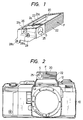
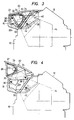
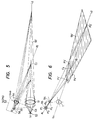
- the flash F and the auxiliary spotlight projector S are both exposed at the same time as shown in Figs. 2 and 4.
- preparation for lighting in the xenon tube 23 of the built-in flash is started and, on the other hand, preparation for spotlighting in the spotlight projector is finished.
- the spotlight projector 26 is energized to radiate a stripe pattern and then the distance from the subject is detected within the camera body 10 by reference to the contrast of the subject corresponding to the stripe pattern.
- the lens is moved to the focusing position based on the distance-detection signal. If the release button is more pushed down, a series of procedures, such as moving-up of the mirror, running of the focal plane and flashing of the xenon tube 23, are perfected.
- the auxiliary spotlight projector for radiating a contrast pattern to measure distance is provided adjacent to the flash of the built-in flash provided to the camera body through the pop-up mechanism. Accordingly, it is not necessary that the auxiliary spotlight projector is provided separately from the flash. Further, if the auxiliary spotlight projector for measuring a distance and the flash are to be used at the same time in the case where the subject is too dark enough to attain contrast, the two can be located in the projecting position at the same time.
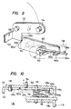
- a first turning lever 132 and a second turning lever 138 are pivoted at their respective one ends on the outside surface of each side plate 124 of the casing 120 through shafts 134 and 140, respectively.
- the shaft 134 is disposed behind the center of the xenon tube 128 and the shaft 140 is disposed at a rear lower portion.
- the first turning lever 132 is pivoted at its other end on a shaft 136 disposed in an upper front portion of a side wall of the housing chamber 116
- the second turning lever 138 is pivoted at its other end on a shaft 142 disposed in a lower rear portion of the same.
- the mechanism for popping up the casing 120 is made up of a four-point linkage formed by the first and second turning levers 132 and 138.
- the pair of first turning levers 132 and the pair of second turning levers 138 are housed in linkage-housing chambers 116b provided at the opposite sides of the housing chamber 116, respectively.
- the pair of first turning levers 132 are connected by a connection arm 133.
- the connection arm 133 acts to secure the interlocking operation of the pair of four-point linkage mechanisms.
- the shaft 142 is disposed on an upper side surface of the penta-prism 114.
- Each of the first turning levers 132 is L-shaped within each of the linkage-housing chambers 116b, and the shaft 136 is disposed at the bent portion of the first turning lever 132.
- the first turning levers 132 are made substantially horizontal and the second turning levers 138 are made frontward downward inclined to thereby hold the collection lens 126 and hence the casing 120 downward.
- the second turning levers 138 are made substantially vertical and the first turning levers 132 are turned to positions where the first turning levers 132 are substantially vertical to thereby assure the height of the casing when projected.
- a pair of switching members 149 each of which is composed of actuating bar 144 and a contact 148, are provided at the opposite ends of the bottom of the housing chamber 116.
- the actuating bar has its top end formed as a projection 146 extending into the housing chamber.
- the switching member 149 serves as a switch of a flashlighting circuit.
- the projection 146 is pressed by the second turning lever 138, so that the actuating bar is disconnected from the contact 148 to open the circuit.
- the second turning lever 138 is departed from the projection 146, so that the actuating bar is in contact with the contact 148 to close the circuit. In this case, preparation for light emission of the built-in flash starts.
- the pair of switching members 149 are provided to secure switching operation sufficiently.
- the ceiling plate 122 of the casing 120 is manually pushed by a finger.
- the casing 120 is retracted into the hosing chamber 116 while the first and second turning levers 132 and 138 turn clockwise.
- the edge 132b of the stoppage/engagement surface 132a of the first turning lever 132 touches the wedge surface 150a of the lock lever 150 to start pressing down the lock lever 150. Accordingly, before the casing 120 reaches the housing position, the edge 132b gets over the top portion of the wedge surface 150a to engage with the wedge surface 150a.
- any space is never produced between the ceiling plate 122 and the housing chamber 116. Further, in the housing position, the second turning lever 138 pushes the projection 146 of the actuating bar 144 to disconnect the actuating bar 144 from the contact 148 to thereby break the flashlighting circuit.
- the illustrated invention shows an example of the pop-up mechanism, but is not limited to the specific embodiment; it may be of course applied with equal utility to other pop-up mechanisms as long as the mechanisms are of the type in which the flash is kept in the housing position by a lever turning with the pop-up operation of the flash and by a lock lever engaged with the lever.
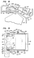
- Fig. 13 and 14 are partly vertical sections respectively taken along the optical axis, showing a camera having a built-in flash as an embodiment according to the present invention.
- a penta-prism 214 is housed in a penta-house 212 provided at an upper portion of a single-lens reflex camera body 210.
- a housing chamber 216 for housing a flash unit 220 of the built-in flash is provided in the upper front of the penta-house 212.
- the flash unit 220 is attached to the housing chamber 216 through a known linkage mechanism by which the flash unit 220 can be moved between a housing position (refer to Fig. 13) where the flash unit 220 is housed in the housing chamber 216 and a projecting position (refer to Fig.2 14) where the flash unit 220 is projected from the housing chamber 216.
- a torsion spring (not shown) is attached to the second lever 238, so that the second lever 238 is urged to move counterclockwise normally, or in other words the flash unit 220 is urged to move upward and forward. Further, a lock member (not shown) for keeping the flash unit 220 in the housing position is provided in the second lever 238 and the penta-house 212.
- the built-in stroboscopic flash has a switch for permitting light emission when the flash unit 220 is in the housing position.
- the conventional housing-type built-in stroboscopic flash can not make light emission when housed, the flash according to the present invention can make light emission through he switch even when housed.
- the aforementioned built-in stroboscopic flash operates as follows.
- the flash unit 220 In normal photographing, the flash unit 220 is kept in the housing position as shown in Fig. 13 when unused. In use, the flash unit 220 is projected to the usable position as shown in Fig. 14 by releasing the stoppage/engagement of the lock member.
- a flash unit having a light emission surface directed toward an object when the flash unit is in the housing condition is provided with a light-transmissible material provided in front of a housing chamber for housing the flash unit so that flashing (light emission) can be made even in the case where the flash unit is housed in the housing chamber. Accordingly, it is possible to light the subject uniformly even in the case of macro photographing. Further, an ND filter or a diffusion lens may be used as the light-transmissible material in the built-in flash to reduce the quantity of light, so that proper exposure in macro photographing can be attained easily.
- flash unit can be moved between the housing position and the projecting position by the electric motor, so that any shock due to the movement of the flash unit between the projecting position and the housing position can be avoided to thereby attain an operational feeling of high rank. Further, the light emission surface of the flash unit can be moved more upward than the direction toward the subject to make bounce-photographing possible without requiring any other outside flash. Accordingly, the capability of a single camera in photographic expression can be widened.
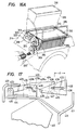
- Fig. 16A shows a modification of the mechanism shown in Fig. 16.
- a drive motor is eliminated and instead thereof, a manually operable screw 320' is adapted to extend to the outside of the camera body in order that the operator may select the flash angle as desired.
- a detection means for controlling the flash position there is no need to provide a detection means for controlling the flash position.
- a pair of cam plates 428 formed by bending upward are disposed on opposite sides of the ground plate 414.
- the cam plates 428 are respectively provided with cam grooves 429 for controlling the attitude of the flash unit 424.
- the cam grooves 429 are provided for insertion of a pair of pins 430 projecting from sides of the flash unit 424 and, more particularly, each cam groove 429 is composed of a housing cam portion 429a, a projecting cam portion 429b and an inclined cam portion 429c, the former two portions 429a and 429b being horizontal, the latter portion 429c being connecting the former two portions.
- the swing arms 433 of the Fresnel lens plate 432 are provided with interlock slots 436 into which interlock pins 438 projecting from the opposite sides of the flash unit 424 are inserted.
- the interlock slots 436 and the interlock pins 438 are arranged so as to locate the Fresnel lens plate 432 in front of the light emission surface 425 in parallel with the former when the flash unit 424 is in the housing position, while so as to interlockingly locate the Fresnel lens plate 432 in front of the light emission surface 25 in parallel with the former when the flash unit turns to the projecting position (normal light emission position).
- the distance l between the light emission surface 425 and the Fresnel lens plate 432 in the normal light emission position may be established by manual operation of a focal length establishing member or may be established by automatic operation in which the position of the slide plates is controlled by the electric motor 421 according to focal-length information as long as the focal-length information can be obtained electrically or mechanically.
- the radiation angle of the built-in flash can be changed. Accordingly, it is made possible to adjust the radiation angle in accordance with the focal length of the camera lens. Further, the flash unit can be moved by the electric motor, so that any shock due to the movement of the flash unit between the projecting position and the housing position can be avoided to thereby attain an operational feeling or high rank.
Landscapes
- Physics & Mathematics (AREA)
- General Physics & Mathematics (AREA)
- Engineering & Computer Science (AREA)
- Multimedia (AREA)
- Signal Processing (AREA)
- Stroboscope Apparatuses (AREA)
Applications Claiming Priority (13)
| Application Number | Priority Date | Filing Date | Title |
|---|---|---|---|
| JP5815/87 | 1987-01-13 | ||
| JP5817/87 | 1987-01-13 | ||
| JP5816/87 | 1987-01-13 | ||
| JP62005817A JPH0614166B2 (ja) | 1987-01-13 | 1987-01-13 | ビルトインフラッシュのポップアップ機構 |
| JP62005815A JPS63173028A (ja) | 1987-01-13 | 1987-01-13 | ビルトインフラツシユを備えた一眼レフカメラ |
| JP62005816A JPS63173029A (ja) | 1987-01-13 | 1987-01-13 | ビルトインフラツシユのポツプアツプ装置の係止機構 |
| JP16209/87 | 1987-02-06 | ||
| JP1987016209U JPS63124224U (fr) | 1987-02-06 | 1987-02-06 | |
| JP2789987A JPH0672992B2 (ja) | 1987-02-09 | 1987-02-09 | カメラのビルトインフラッシュ装置 |
| JP27898/87 | 1987-02-09 | ||
| JP27899/87 | 1987-02-09 | ||
| JP62027898A JPH0666022B2 (ja) | 1987-02-09 | 1987-02-09 | カメラのビルトインフラッシュ装置 |
| EP88100384A EP0275089B1 (fr) | 1987-01-13 | 1988-01-13 | Système de flash incorporé et caméra |
Related Parent Applications (1)
| Application Number | Title | Priority Date | Filing Date |
|---|---|---|---|
| EP88100384.2 Division | 1988-01-13 |
Publications (3)
| Publication Number | Publication Date |
|---|---|
| EP0463645A2 true EP0463645A2 (fr) | 1992-01-02 |
| EP0463645A3 EP0463645A3 (en) | 1992-07-08 |
| EP0463645B1 EP0463645B1 (fr) | 1994-05-04 |
Family
ID=27547938
Family Applications (6)
| Application Number | Title | Priority Date | Filing Date |
|---|---|---|---|
| EP91116116A Expired - Lifetime EP0464873B1 (fr) | 1987-01-13 | 1988-01-13 | Système de flash incorporé et caméra |
| EP91116130A Expired - Lifetime EP0468541B1 (fr) | 1987-01-13 | 1988-01-13 | Système de flash incorporé et caméra |
| EP91116129A Expired - Lifetime EP0463645B1 (fr) | 1987-01-13 | 1988-01-13 | Système de flash incorporé et caméra |
| EP91116131A Expired - Lifetime EP0463646B1 (fr) | 1987-01-13 | 1988-01-13 | Système de flash incorporé et caméra |
| EP88100384A Expired - Lifetime EP0275089B1 (fr) | 1987-01-13 | 1988-01-13 | Système de flash incorporé et caméra |
| EP91116117A Expired - Lifetime EP0466214B1 (fr) | 1987-01-13 | 1988-01-13 | Système de flash incorporé et caméra |
Family Applications Before (2)
| Application Number | Title | Priority Date | Filing Date |
|---|---|---|---|
| EP91116116A Expired - Lifetime EP0464873B1 (fr) | 1987-01-13 | 1988-01-13 | Système de flash incorporé et caméra |
| EP91116130A Expired - Lifetime EP0468541B1 (fr) | 1987-01-13 | 1988-01-13 | Système de flash incorporé et caméra |
Family Applications After (3)
| Application Number | Title | Priority Date | Filing Date |
|---|---|---|---|
| EP91116131A Expired - Lifetime EP0463646B1 (fr) | 1987-01-13 | 1988-01-13 | Système de flash incorporé et caméra |
| EP88100384A Expired - Lifetime EP0275089B1 (fr) | 1987-01-13 | 1988-01-13 | Système de flash incorporé et caméra |
| EP91116117A Expired - Lifetime EP0466214B1 (fr) | 1987-01-13 | 1988-01-13 | Système de flash incorporé et caméra |
Country Status (5)
| Country | Link |
|---|---|
| US (1) | US4920368A (fr) |
| EP (6) | EP0464873B1 (fr) |
| KR (1) | KR950008340B1 (fr) |
| CA (1) | CA1319848C (fr) |
| DE (6) | DE3889471T2 (fr) |
Cited By (1)
| Publication number | Priority date | Publication date | Assignee | Title |
|---|---|---|---|---|
| EP0614109A1 (fr) * | 1993-03-01 | 1994-09-07 | Eastman Kodak Company | Dispositif de flash pivotable à la main avec changement de focalisation |
Families Citing this family (26)
| Publication number | Priority date | Publication date | Assignee | Title |
|---|---|---|---|---|
| US4970539A (en) * | 1987-12-21 | 1990-11-13 | Nikon Corporation | Camera with incorporated flash device |
| JPH0643770Y2 (ja) * | 1987-12-28 | 1994-11-14 | 旭光学工業株式会社 | 自動焦点一眼レフカメラの合焦補助投光装置 |
| US5160192A (en) * | 1988-03-16 | 1992-11-03 | Asahi Kogaku Kogyo Kabushiki Kaisha | Illuminating instrument |
| US5138361A (en) * | 1988-03-31 | 1992-08-11 | Asahi Kogaku Kogyo K.K. | Electronic flash control device employing a plurality of control signals |
| JPH0516585Y2 (fr) * | 1988-03-31 | 1993-04-30 | ||
| US4982210A (en) * | 1988-05-11 | 1991-01-01 | Minolta Camera Kabushiki Kaisha | Flash device |
| JPH0538338Y2 (fr) * | 1988-07-29 | 1993-09-28 | ||
| JPH0645938Y2 (ja) * | 1988-07-29 | 1994-11-24 | 旭光学工業株式会社 | ストロボ内蔵一眼レフカメラ |
| JPH02207230A (ja) * | 1989-02-07 | 1990-08-16 | Nikon Corp | 電子閃光装置 |
| JPH02126136U (fr) * | 1989-03-27 | 1990-10-17 | ||
| US5253003A (en) * | 1989-05-24 | 1993-10-12 | Minolta Camera Kabushiki Kaisha | Flash-integrated camera |
| US5079574A (en) * | 1989-08-17 | 1992-01-07 | Asahi Kogaku Kogyo Kabushiki Kaisha | Motor-driven camera |
| USRE35415E (en) * | 1989-10-06 | 1996-12-31 | Asahi Kogaku Kogyo Kabushiki Kaisha | Camera having an automatically operated built-in strobe |
| GB2237119B (en) * | 1989-10-06 | 1994-06-08 | Asahi Optical Co Ltd | Strobe control apparatus of camera |
| US5122829A (en) * | 1989-10-06 | 1992-06-16 | Asahi Kogaku Kogyo Kabushiki Kaisha | Camera having an automatically operating built-in strobe |
| JP2808328B2 (ja) * | 1989-10-19 | 1998-10-08 | 旭光学工業株式会社 | カメラのストロボ制御装置 |
| US5179401A (en) * | 1991-03-18 | 1993-01-12 | Eastman Kodak Company | Photographic camera with wedge-shaped body portion and matching flash |
| US5255032A (en) * | 1992-07-23 | 1993-10-19 | Eastman Kodak Company | Compact camera with deployable flash unit |
| JP3411729B2 (ja) * | 1995-08-15 | 2003-06-03 | ペンタックス株式会社 | ストロボ装置内蔵カメラ装置 |
| JPH10206944A (ja) * | 1997-01-23 | 1998-08-07 | Asahi Optical Co Ltd | ストロボ内蔵カメラ |
| US6104882A (en) * | 1997-01-30 | 2000-08-15 | Asahi Kogaku Kogyo Kabushiki Kaisha | Camera having a built-in retractable flash |
| US6304728B1 (en) | 2000-03-14 | 2001-10-16 | Concord Camera Corp. | Camera with flash unit disposed in between viewfinder lenses |
| JP2002090841A (ja) * | 2000-09-12 | 2002-03-27 | Fuji Photo Optical Co Ltd | カメラ |
| KR101156680B1 (ko) * | 2005-01-12 | 2012-06-14 | 삼성전자주식회사 | 스트로보 팝업 기구 및 이를 구비한 카메라 장치 |
| JP2008040389A (ja) * | 2006-08-10 | 2008-02-21 | Olympus Imaging Corp | 一眼レフレツクスカメラ |
| CN101770140B (zh) * | 2009-01-06 | 2011-11-16 | 亚洲光学股份有限公司 | 闪光灯的自动开启装置 |
Family Cites Families (15)
| Publication number | Priority date | Publication date | Assignee | Title |
|---|---|---|---|---|
| US2783696A (en) * | 1951-06-23 | 1957-03-05 | Voigtlaender Ag | Flash lamp equipment |
| GB1095686A (en) * | 1965-11-23 | 1967-12-20 | Rollei Werke Franke Heidecke | Photographic camera with flash attachment |
| US4067030A (en) * | 1975-01-24 | 1978-01-03 | Minolta Camera Kabushiki Kaisha | Camera focussing aid |
| DE2848809C2 (de) * | 1978-11-10 | 1982-12-16 | Kodak Ag, 7000 Stuttgart | Photographische Klappkamera |
| GB2062260B (en) * | 1979-08-31 | 1983-05-18 | West Electric Co | Camera |
| DE2940301C2 (de) * | 1979-10-04 | 1982-05-13 | Agfa-Gevaert Ag, 5090 Leverkusen | Fotografische Kamera mit einem Elektronenblitzgerät |
| US4473285A (en) * | 1981-11-27 | 1984-09-25 | W. Haking Enterprises Limited | Automatic focusing camera |
| JPS58208735A (ja) * | 1982-05-28 | 1983-12-05 | Fuji Photo Optical Co Ltd | カメラのストロボ装置 |
| GB2106261A (en) * | 1982-06-02 | 1983-04-07 | Hen Long Tseng | Camera having integral flash |
| JPS59210426A (ja) * | 1983-05-14 | 1984-11-29 | Nippon Kogaku Kk <Nikon> | 閃光装置内蔵カメラ |
| JPS6060729U (ja) * | 1983-10-03 | 1985-04-27 | 富士写真フイルム株式会社 | ストロボ内蔵広角・望遠撮影切換えカメラ |
| DE8336141U1 (de) * | 1983-12-16 | 1984-03-15 | Kodak Ag, 7000 Stuttgart | Kleinbildkamera kompakter bauart |
| DE3639751C3 (de) * | 1985-11-22 | 2000-06-29 | Asahi Optical Co Ltd | Einäugige Spiegelreflexkamera |
| US4755838A (en) * | 1987-04-09 | 1988-07-05 | Lemmey Edgar S | Close-up camera apparatus |
| US4734733A (en) * | 1987-09-21 | 1988-03-29 | Polaroid Corporation | Camera with two position strobe |
-
1988
- 1988-01-13 DE DE3889471T patent/DE3889471T2/de not_active Expired - Fee Related
- 1988-01-13 EP EP91116116A patent/EP0464873B1/fr not_active Expired - Lifetime
- 1988-01-13 EP EP91116130A patent/EP0468541B1/fr not_active Expired - Lifetime
- 1988-01-13 DE DE3889468T patent/DE3889468T2/de not_active Expired - Fee Related
- 1988-01-13 EP EP91116129A patent/EP0463645B1/fr not_active Expired - Lifetime
- 1988-01-13 EP EP91116131A patent/EP0463646B1/fr not_active Expired - Lifetime
- 1988-01-13 KR KR1019880000170A patent/KR950008340B1/ko not_active Expired - Fee Related
- 1988-01-13 DE DE3886226T patent/DE3886226T2/de not_active Expired - Fee Related
- 1988-01-13 DE DE3889466T patent/DE3889466T2/de not_active Expired - Fee Related
- 1988-01-13 EP EP88100384A patent/EP0275089B1/fr not_active Expired - Lifetime
- 1988-01-13 CA CA000556419A patent/CA1319848C/fr not_active Expired - Fee Related
- 1988-01-13 EP EP91116117A patent/EP0466214B1/fr not_active Expired - Lifetime
- 1988-01-13 DE DE3889469T patent/DE3889469T2/de not_active Expired - Fee Related
- 1988-01-13 DE DE3889344T patent/DE3889344T2/de not_active Expired - Fee Related
-
1989
- 1989-02-03 US US07/306,436 patent/US4920368A/en not_active Expired - Lifetime
Cited By (1)
| Publication number | Priority date | Publication date | Assignee | Title |
|---|---|---|---|---|
| EP0614109A1 (fr) * | 1993-03-01 | 1994-09-07 | Eastman Kodak Company | Dispositif de flash pivotable à la main avec changement de focalisation |
Also Published As
| Publication number | Publication date |
|---|---|
| DE3889468D1 (de) | 1994-06-09 |
| EP0463646B1 (fr) | 1994-05-04 |
| EP0468541A3 (en) | 1992-07-01 |
| DE3889471D1 (de) | 1994-06-09 |
| EP0275089A3 (en) | 1988-09-28 |
| EP0463645A3 (en) | 1992-07-08 |
| DE3889469T2 (de) | 1994-09-29 |
| EP0464873A3 (en) | 1992-07-08 |
| EP0463646A3 (en) | 1992-07-08 |
| EP0466214A2 (fr) | 1992-01-15 |
| EP0463645B1 (fr) | 1994-05-04 |
| EP0463646A2 (fr) | 1992-01-02 |
| EP0466214A3 (en) | 1992-07-08 |
| DE3889468T2 (de) | 1994-09-29 |
| KR950008340B1 (ko) | 1995-07-27 |
| US4920368A (en) | 1990-04-24 |
| EP0464873B1 (fr) | 1994-05-04 |
| KR880009289A (ko) | 1988-09-14 |
| EP0275089A2 (fr) | 1988-07-20 |
| DE3889471T2 (de) | 1994-09-29 |
| EP0468541A2 (fr) | 1992-01-29 |
| DE3889466D1 (de) | 1994-06-09 |
| EP0468541B1 (fr) | 1994-05-04 |
| EP0275089B1 (fr) | 1993-12-15 |
| DE3886226T2 (de) | 1994-05-19 |
| EP0464873A2 (fr) | 1992-01-08 |
| DE3889469D1 (de) | 1994-06-09 |
| DE3889344D1 (de) | 1994-06-01 |
| DE3889344T2 (de) | 1994-09-01 |
| EP0466214B1 (fr) | 1994-04-27 |
| CA1319848C (fr) | 1993-07-06 |
| DE3889466T2 (de) | 1994-09-29 |
| DE3886226D1 (de) | 1994-01-27 |
Similar Documents
| Publication | Publication Date | Title |
|---|---|---|
| EP0466214B1 (fr) | Système de flash incorporé et caméra | |
| US5329327A (en) | Built-in flash system | |
| US4067030A (en) | Camera focussing aid | |
| JPH0666023B2 (ja) | ズームレンズおよび照射角可変ストロボ装置を備えたカメラ | |
| JPH0643770Y2 (ja) | 自動焦点一眼レフカメラの合焦補助投光装置 | |
| US5287135A (en) | Built-in flash system | |
| KR0156376B1 (ko) | 카메라의 내장 플래시 장치 | |
| CA1324282C (fr) | Systeme integre de lampe-eclair | |
| US20020071669A1 (en) | Interconnection device of zoom camera | |
| EP0038045B1 (fr) | Caméra à système macrophotographique | |
| JPH095843A (ja) | カメラ | |
| US5305037A (en) | Strobe device of camera | |
| JP2761772B2 (ja) | カメラのセルフ表示装置 | |
| JP3703330B2 (ja) | カメラ | |
| JP2000162738A (ja) | レンズ付きフイルムユニット | |
| WO1992014186A2 (fr) | Appareil photographique a mode photographique variable | |
| JP3752036B2 (ja) | ファインダの視野枠切換装置 | |
| JPH09281577A (ja) | カメラ | |
| JP4038084B2 (ja) | レンズ付きフイルムユニット | |
| JP4390915B2 (ja) | 電子閃光装置および該電子閃光装置搭載の撮像装置 | |
| JP2885440B2 (ja) | カメラ | |
| JPH03126018A (ja) | カメラのストロボ制御装置 | |
| JPH0651193A (ja) | 撮影モード切換カメラ | |
| JPH03123334A (ja) | カメラのストロボ制御装置 | |
| JPH0651366A (ja) | 撮影モード切換カメラ |
Legal Events
| Date | Code | Title | Description |
|---|---|---|---|
| PUAI | Public reference made under article 153(3) epc to a published international application that has entered the european phase |
Free format text: ORIGINAL CODE: 0009012 |
|
| AC | Divisional application: reference to earlier application |
Ref document number: 275089 Country of ref document: EP |
|
| AK | Designated contracting states |
Kind code of ref document: A2 Designated state(s): DE FR GB |
|
| RIN1 | Information on inventor provided before grant (corrected) |
Inventor name: TETSUJI, SHONO, C/O ASAHI KOGAKU KOGYO K.K. Inventor name: AKIHIRO, ARAI, C/O ASAHI KOGAKU KOGYO K.K. |
|
| PUAL | Search report despatched |
Free format text: ORIGINAL CODE: 0009013 |
|
| AK | Designated contracting states |
Kind code of ref document: A3 Designated state(s): DE FR GB |
|
| 17P | Request for examination filed |
Effective date: 19921216 |
|
| 17Q | First examination report despatched |
Effective date: 19930301 |
|
| GRAA | (expected) grant |
Free format text: ORIGINAL CODE: 0009210 |
|
| AC | Divisional application: reference to earlier application |
Ref document number: 275089 Country of ref document: EP |
|
| AK | Designated contracting states |
Kind code of ref document: B1 Designated state(s): DE FR GB |
|
| REF | Corresponds to: |
Ref document number: 3889466 Country of ref document: DE Date of ref document: 19940609 |
|
| ET | Fr: translation filed | ||
| PLBE | No opposition filed within time limit |
Free format text: ORIGINAL CODE: 0009261 |
|
| STAA | Information on the status of an ep patent application or granted ep patent |
Free format text: STATUS: NO OPPOSITION FILED WITHIN TIME LIMIT |
|
| 26N | No opposition filed | ||
| REG | Reference to a national code |
Ref country code: GB Ref legal event code: IF02 |
|
| PGFP | Annual fee paid to national office [announced via postgrant information from national office to epo] |
Ref country code: GB Payment date: 20040107 Year of fee payment: 17 |
|
| PGFP | Annual fee paid to national office [announced via postgrant information from national office to epo] |
Ref country code: FR Payment date: 20040108 Year of fee payment: 17 |
|
| PGFP | Annual fee paid to national office [announced via postgrant information from national office to epo] |
Ref country code: DE Payment date: 20050106 Year of fee payment: 18 |
|
| PG25 | Lapsed in a contracting state [announced via postgrant information from national office to epo] |
Ref country code: GB Free format text: LAPSE BECAUSE OF NON-PAYMENT OF DUE FEES Effective date: 20050113 |
|
| GBPC | Gb: european patent ceased through non-payment of renewal fee |
Effective date: 20050113 |
|
| PG25 | Lapsed in a contracting state [announced via postgrant information from national office to epo] |
Ref country code: FR Free format text: LAPSE BECAUSE OF NON-PAYMENT OF DUE FEES Effective date: 20050930 |
|
| REG | Reference to a national code |
Ref country code: FR Ref legal event code: ST |
|
| PG25 | Lapsed in a contracting state [announced via postgrant information from national office to epo] |
Ref country code: DE Free format text: LAPSE BECAUSE OF NON-PAYMENT OF DUE FEES Effective date: 20060801 |