EP0463885A2 - Circuit de déaccentuation non linéaire - Google Patents
Circuit de déaccentuation non linéaire Download PDFInfo
- Publication number
- EP0463885A2 EP0463885A2 EP91305904A EP91305904A EP0463885A2 EP 0463885 A2 EP0463885 A2 EP 0463885A2 EP 91305904 A EP91305904 A EP 91305904A EP 91305904 A EP91305904 A EP 91305904A EP 0463885 A2 EP0463885 A2 EP 0463885A2
- Authority
- EP
- European Patent Office
- Prior art keywords
- circuit
- amplitude
- signal
- linear
- limited signal
- Prior art date
- Legal status (The legal status is an assumption and is not a legal conclusion. Google has not performed a legal analysis and makes no representation as to the accuracy of the status listed.)
- Granted
Links
Images



Classifications
-
- G—PHYSICS
- G11—INFORMATION STORAGE
- G11B—INFORMATION STORAGE BASED ON RELATIVE MOVEMENT BETWEEN RECORD CARRIER AND TRANSDUCER
- G11B20/00—Signal processing not specific to the method of recording or reproducing; Circuits therefor
- G11B20/24—Signal processing not specific to the method of recording or reproducing; Circuits therefor for reducing noise
-
- G—PHYSICS
- G11—INFORMATION STORAGE
- G11B—INFORMATION STORAGE BASED ON RELATIVE MOVEMENT BETWEEN RECORD CARRIER AND TRANSDUCER
- G11B20/00—Signal processing not specific to the method of recording or reproducing; Circuits therefor
- G11B20/02—Analogue recording or reproducing
-
- H—ELECTRICITY
- H03—ELECTRONIC CIRCUITRY
- H03G—CONTROL OF AMPLIFICATION
- H03G5/00—Tone control or bandwidth control in amplifiers
- H03G5/16—Automatic control
- H03G5/18—Automatic control in untuned amplifiers
-
- H—ELECTRICITY
- H04—ELECTRIC COMMUNICATION TECHNIQUE
- H04N—PICTORIAL COMMUNICATION, e.g. TELEVISION
- H04N5/00—Details of television systems
- H04N5/76—Television signal recording
- H04N5/91—Television signal processing therefor
- H04N5/92—Transformation of the television signal for recording, e.g. modulation, frequency changing; Inverse transformation for playback
- H04N5/923—Transformation of the television signal for recording, e.g. modulation, frequency changing; Inverse transformation for playback using preemphasis of the signal before modulation and deemphasis of the signal after demodulation
Definitions
- This invention relates to non-linear de-emphasis circuits which may, for example, be used in video tape recorders.
- Video tape recorders are generally designed such that a nonlinear emphasis circuit and a non-linear de-emphasis circuit are included in order to ensure that the reproduced signal has a high signal-to-noise (SN) ratio.
- SN signal-to-noise
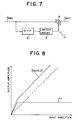
- Non-linear emphasis circuit 1 is arranged such that high frequency components of a recording signal S REC are extracted by a high-pass filter circuit (HPF) 2, and then the filtered recording signal S REC is supplied to an adding circuit 4 by way of a limiter circuit 3.
- HPF high-pass filter circuit
- the output signal from the limiter circuit 3 is added to the original recording signal S REC by the adding circuit 4 to produce an output signal S OUT to be recorded on to a magnetic tape. Consequently, the recording signal S REC is recorded with the high frequency components of low amplitude emphasised as seen from another curve L2 shown in Figure 8.
- FIG. 9 An example of a previously-proposed non-linear de-emphasis circuit is shown in Figure 9.
- the non-linear de-emphasis circuit 5 is arranged such that a reproduction signal S RF reproduced from the magnetic tape is applied to a differential amplifier circuit 6, and a feedback loop to the differential amplifier circuit 6 is formed by a high-pass filter circuit (HPF) 7, a limiter circuit 8 and an adding circuit 9.
- HPF high-pass filter circuit
- the characteristics of the high-pass filter circuit 7, the limiter circuit 8 and the adding circuit 9 are set to the same characteristics (shown by a curve L3 in Figure 10) as those of the high-pass filter circuit 2, the limiter circuit 3 and the adding circuit 4 of the non-linear emphasis circuit 1, so that the reproduction signal S RF may be corrected with an inverse characteristic to that of the non-linear emphasis circuit 1 (the output signal from the non-linear de-emphasis circuit 5 is illustrated by a curve S RF1 in Figure 10).
- the transfer function of the recording and reproducing system is set to unity to suppress noise components of low amplitude at high frequency.
- non-linear de-emphasis circuit 10 includes a limiter circuit 12 to effect amplitude limiting separately in order to raise the effect of improvement in SN ratio.
- a reproduction signal S RF is received at a subtracting circuit 13, and the output signal of the subtracting circuit 13 is supplied via a high-pass filter circuit (HPF) 7 and a limiter circuit 8 back to the subtracting input of the subtracting circuit 13.
- HPF high-pass filter circuit
- the output signal of the limiter circuit 8 is subtracted from the reproduction signal S RF . Accordingly, a similar characteristic to that of the non-linear de-emphasis circuit 5 (wherein a feedback loop to the differential amplifier circuit 6 is formed as described hereinabove with reference to Figure 9) is obtained.
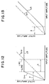
- the limiter circuit 12 amplitude limits an input signal thereto to a value LIM2 which is lower than a maximum output amplitude LIM1 of the limiter circuit 8.
- the gain x of the limiter circuit 12 and the attenuator 14, when the amplitude of the output signal of the limiter circuit 8 is low, is maintained such that it may satisfy the following expression: ⁇ ⁇ x ⁇ 1 + A ⁇ A
- A is the gain of the high-pass filter circuit 7 and the limiter circuit 8 at a low amplitude and high frequency
- ⁇ is the gain of an attenuator 18 interposed between the output of the limiter circuit 8 and the subtracting input of the subtracting circuit 13.
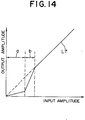
- the input/output characteristic of the limiter circuit 12 and the attenuator 14 is set as shown by a curve L5 in Figure 12.
- a non-linear de-emphasis circuit comprising: a first subtracting circuit for subtracting an amplitude limited signal from an input signal; a high-pass filter circuit for extracting high frequency components from the output signal from said first subtracting circuit; a first limiter circuit for amplitude limiting the output signal from said high-pass filter circuit to produce said amplitude limited signal for supply to said first subtracting circuit; a non-linear amplifier circuit for amplifying, when the amplitude limited signal has a lower amplitude than an amplitude limiting value of said first limiter circuit, the amplitude limited signal with a gain greater than a predetermined value, said non-linear amplifier circuit being operable in response to an increase in amplitude of the amplitude limited signal to alter the input/output characteristic thereof such that, when the amplitude of the amplitude limited signal is equal to or greater than the amplitude limiting value of said first limiter circuit, said non-linear amplifier circuit amplifies the amplitude limited signal with
- the non-linear amplifier circuit which amplifies, when the amplitude limited signal has a lower amplitude than an amplitude limiting value of the first limiter circuit, the amplitude limited signal with a gain greater than the predetermined value (such as unity), but changes over the input/output characteristic thereof in response to an increase in amplitude of the amplitude limited signal such that, when the amplitude of the amplitude limited signal is equal to or higher than the amplitude limited value of the first limiter circuit, the non-linear amplifier circuit amplifies the amplitude limited signal with a gain equal to the predetermined value.
- the predetermined value such as unity
- the non-linear de-emphasis circuit has an improved SN ratio and a simple construction without causing deterioration in a delicate waveform of the reproduced signal.
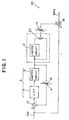
- the non-linear de-emphasis circuit 20 has similarities in construction to the previously-proposed non-linear de-emphasis circuit 10 described hereinabove with reference to Figure 11. Accordingly, only the components not present in the circuit 10 of Figure 11 will be described in detail.
- the non-linear de-emphasis circuit 20 additionally includes a mixer 22 interposed between the limiter circuit 12 and the attenuator 14 such that input and output signals of the limiter circuit 12 are mixed at a desired ratio, and the resulting mixed signal is supplied to the attenuator 14.
- the region in which high frequency low amplitudes are suppressed is decreased within a sufficient range for practical use compared with the previously-proposed non-linear de-emphasis circuit, and the SN ratio can be improved without damaging a delicate contour of a reproduced picture image.
- the characteristic of the nonlinear de-emphasis circuit 20 can be chosen freely from between the characteristic of the non-linear de-emphasis circuit 5 described hereinabove with reference to Figure 9 and the characteristic of the non-linear de-emphasis circuit 10 described hereinabove with reference to Figure 11; a wide range of desired noise reducing effects can thus be provided.
- the subtracting circuit 13 constitutes a subtracting circuit for subtracting an amplitude limited signal from an input signal S RF
- the high-pass filter circuit 7 constitutes a high-pass filter circuit for extracting high frequency components from an output signal of the subtracting circuit 13.
- the limiter circuit 8 constitutes a limiter circuit for amplitude limiting an output signal of the high-pass filter circuit 7 to produce the amplitude limited signal
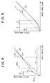
- the limiter circuit 12 and the mixer 22 constitute a non-linear amplifier circuit which amplifies, at a lower amplitude (a1) than the amplitude limiting value LIM1 of the limiter circuit 8, the amplitude limited signal with a gain higher than unity, but which changes over, in response to an increase in amplitude, the input/output characteristic thereof such that, when the amplitude limiting value LIM1 of the limiter circuit 8 is reached, it amplifies the amplitude limited signal with a gain equal to unity;
- the subtracting circuit 16 constitutes a subtracting circuit for subtracting an output signal of the non-linear amplifier circuit from the input signal S RF .
- a reproduction signal S RF is supplied by way of the subtracting circuit 13 to the high-pass filter 7, at which high frequency components are extracted from the reproduction signal S RF , whereafter the filtered reproduction signal is amplitude limited by the limiter circuit 8.
- the output signal from the limiter circuit 8 is fed back to the subtracting circuit 13 by way of the attenuator 18, and is also supplied to the non-linear amplifier circuit.
- the output signal from the limiter circuit 8 is amplitude limited by the limiter circuit 12, and the amplitude limited signal is mixed with the output signal from the limiter circuit 8 by means of the mixer 22; the output signal from the mixer 22 is then supplied to the subtracting circuit 16 by way of the attenuator 14.
- the output signal from the limiter circuit 8 is subtracted from the original reproduction signal S RF . Consequently, an inverse characteristic to that of the non-linear emphasis circuit is obtained.
- the output signal from the limiter circuit 8 is further amplitude limited by the limiter circuit 12, mixed by the mixer 22 and then subtracted from the original reproduction signal S RF , high frequency components can be suppressed in the region a1 in which the amplitude is sufficiently lower than the amplitude limiting value LIM2 of the limiter circuit 12, and the SN ratio can be improved without damaging delicate contours of a reproduced picture image.
- the output signal from the limiter circuit 8 when the output signal from the limiter circuit 8 is to be subtracted from the reproduction signal to obtain an inverse characteristic to that of a non-linear emphasis circuit, it is first amplitude limited by the limiter circuit 12 and mixed by the mixer 22, and then subtracted from the original reproduction signal S RF . Consequently, high frequency components can be suppressed in the region a1 in which the amplitude is lower than the amplitude limiting value LIM2 of the limiter circuit 12, and the SN ratio can be improved by means of a simple construction without damaging delicate contours of a reproduced picture image.
- the non-linear amplifier circuit is constituted by the limiter circuit 12 and the mixer 22.
- the characteristic shown in Figure 2 can alternatively be obtained by means of non-linear amplifier circuits of various different constructions.
- An example of such an alternative non-linear amplifier circuit is shown in Figure 5.
- the non-linear amplifier circuit 30 is constituted such that the output signal from the limiter circuit 8 is applied to an amplifier circuit 32, and the output signal from the amplifier circuit 32 is supplied to the attenuator 14 by way of a resistor 34.
- the output end of the resistor 34 (adjacent the attenuator 14) is connected to the emitters of a pair of transistors 36 and 38 by way of a resistor 35.
- the collectors of the transistors 36 and 38 are connected to a power source line Vcc and to earth, respectively, so that they may be switched to an on-state in response to a potential difference E between the bases thereof as seen in Figure 6.
- the output signal from the limiter circuit 8 is supplied, at low amplitude, with an impedance which is set by the resistor 34, but as the amplitude increases, it is supplied at a signal level provided by voltage division by means of the resistors 34 and 35.
- a non-linear amplifier circuit having the same characteristic as the non-linear amplifier circuit shown in Figure 1 can be obtained by selecting suitable resistance values of the resistors 34 and 35 and a suitable gain of the amplifier circuit 32.
- the invention may equally well be applied to other recording/reproduction systems.
- the invention may be applied to a reproduction system for a video signal, or even to a reproduction system for an audio signal, thereby improving the SN ratio while minimising the distortion in the reproduced signal.
Landscapes
- Engineering & Computer Science (AREA)
- Signal Processing (AREA)
- Multimedia (AREA)
- Television Signal Processing For Recording (AREA)
- Picture Signal Circuits (AREA)
- Tone Control, Compression And Expansion, Limiting Amplitude (AREA)
Applications Claiming Priority (2)
| Application Number | Priority Date | Filing Date | Title |
|---|---|---|---|
| JP173725/90 | 1990-06-29 | ||
| JP2173725A JP2982233B2 (ja) | 1990-06-29 | 1990-06-29 | ノンリニアデエンフアシス回路 |
Publications (3)
| Publication Number | Publication Date |
|---|---|
| EP0463885A2 true EP0463885A2 (fr) | 1992-01-02 |
| EP0463885A3 EP0463885A3 (en) | 1993-03-03 |
| EP0463885B1 EP0463885B1 (fr) | 1997-08-27 |
Family
ID=15965988
Family Applications (1)
| Application Number | Title | Priority Date | Filing Date |
|---|---|---|---|
| EP91305904A Expired - Lifetime EP0463885B1 (fr) | 1990-06-29 | 1991-06-28 | Circuit de déaccentuation non linéaire |
Country Status (5)
| Country | Link |
|---|---|
| US (1) | US5182520A (fr) |
| EP (1) | EP0463885B1 (fr) |
| JP (1) | JP2982233B2 (fr) |
| KR (1) | KR100236362B1 (fr) |
| DE (1) | DE69127408T2 (fr) |
Families Citing this family (4)
| Publication number | Priority date | Publication date | Assignee | Title |
|---|---|---|---|---|
| EP1821474B1 (fr) * | 2006-02-17 | 2012-05-30 | Fujitsu Limited | Appareil de suppression de pics de voltage d' un signal |
| KR101016598B1 (ko) * | 2008-09-09 | 2011-02-22 | 주식회사 동구전자 | 원두커피 제조장치 |
| EP2541895B1 (fr) * | 2010-02-26 | 2019-01-02 | Sharp Kabushiki Kaisha | Appareil de traitement d'image, appareil d'affichage le comportant, et procédé de traitement d'image |
| US11936211B2 (en) * | 2021-05-05 | 2024-03-19 | Aira, Inc. | Mixed analog front-end for wireless charging |
Family Cites Families (10)
| Publication number | Priority date | Publication date | Assignee | Title |
|---|---|---|---|---|
| US3654563A (en) * | 1965-10-15 | 1972-04-04 | Gen Electric | Active filter circuit having nonlinear properties |
| JPS6030285A (ja) * | 1983-07-29 | 1985-02-15 | Victor Co Of Japan Ltd | 映像信号記録再生装置 |
| JPS6030296A (ja) * | 1983-07-29 | 1985-02-15 | Victor Co Of Japan Ltd | 映像信号記録装置及び映像信号記録再生装置 |
| US4682251A (en) * | 1984-03-21 | 1987-07-21 | Victor Company Of Japan, Ltd. | Video signal reproducing apparatus having a noise reduction circuit |
| KR910000368B1 (ko) * | 1984-09-12 | 1991-01-24 | 마쯔시다덴기산교 가부시기가이샤 | 비선형 신호처리장치 |
| JPS6318811A (ja) * | 1986-07-11 | 1988-01-26 | Victor Co Of Japan Ltd | 雑音低減回路 |
| US4849826A (en) * | 1986-11-14 | 1989-07-18 | Matsushita Electric Industrial Co., Ltd. | Digital non-linear pre-emphasis/de-emphasis apparatus for eliminating noise components from video signals in a video signal processing system |
| US4864404A (en) * | 1987-05-22 | 1989-09-05 | Victor Company Of Japan, Ltd. | Noise reduction circuit of a video signal |
| JPH0744135Y2 (ja) * | 1988-06-20 | 1995-10-09 | ソニー株式会社 | 輪郭強調回路 |
| US5126846A (en) * | 1988-08-08 | 1992-06-30 | Kabushiki Kaisha Toshiba | Non-linear amplifier and non-linear emphasis/deemphasis circuit using the same |
-
1990
- 1990-06-29 JP JP2173725A patent/JP2982233B2/ja not_active Expired - Fee Related
-
1991
- 1991-06-27 US US07/722,161 patent/US5182520A/en not_active Expired - Fee Related
- 1991-06-28 EP EP91305904A patent/EP0463885B1/fr not_active Expired - Lifetime
- 1991-06-28 KR KR1019910010849A patent/KR100236362B1/ko not_active Expired - Fee Related
- 1991-06-28 DE DE69127408T patent/DE69127408T2/de not_active Expired - Fee Related
Also Published As
| Publication number | Publication date |
|---|---|
| EP0463885B1 (fr) | 1997-08-27 |
| DE69127408T2 (de) | 1998-02-05 |
| US5182520A (en) | 1993-01-26 |
| JPH0463079A (ja) | 1992-02-28 |
| EP0463885A3 (en) | 1993-03-03 |
| DE69127408D1 (de) | 1997-10-02 |
| KR920001494A (ko) | 1992-01-30 |
| KR100236362B1 (ko) | 1999-12-15 |
| JP2982233B2 (ja) | 1999-11-22 |
Similar Documents
| Publication | Publication Date | Title |
|---|---|---|
| EP0292324B1 (fr) | Circuit de réduction de bruit pour un signal vidéo | |
| US4263624A (en) | Analog recording on magnetic media | |
| EP0463885B1 (fr) | Circuit de déaccentuation non linéaire | |
| US4326223A (en) | Video signal recording and/or reproducing apparatus with gain control | |
| US5276403A (en) | Nonlinear preemphasis-deemphasis system | |
| US4122502A (en) | Playback system for a magnetic tape recorder | |
| US5493341A (en) | Digital non-linear pre-emphasis/de-emphasis apparatus for video signals in a video signal recording and reproducing apparatus | |
| JPH0341882B2 (fr) | ||
| KR100213073B1 (ko) | 재생 오디오 신호의 주파수 특성 보상 장치 | |
| US5309297A (en) | Digital cassette tape reproducing device including novel drive circuit | |
| US5828762A (en) | Apparatus for compensating audio signal recording | |
| JPH05292454A (ja) | ノンリニアエンファシス回路 | |
| JP2937328B2 (ja) | 非線形エンファシス・ディエンファシス回路 | |
| US5179476A (en) | Signal processor | |
| JP3139050B2 (ja) | Fm等化回路及びこれを用いた記録再生装置 | |
| JP2831996B2 (ja) | 信号記録装置 | |
| JPS5811125B2 (ja) | フイルタ装置 | |
| JPH0758559A (ja) | スルーレート制御増幅器 | |
| JPH04117874A (ja) | 映像信号処理装置 | |
| JPH05325406A (ja) | 情報信号の記録再生装置 | |
| JPH0659010B2 (ja) | Fm信号復調器 | |
| GB2117548A (en) | Magnetic recording systems | |
| JPS63290476A (ja) | エンファシス回路 | |
| JPS6013621B2 (ja) | ノイズリダクシヨンシステム | |
| JPS60223397A (ja) | カラ−信号処理回路 |
Legal Events
| Date | Code | Title | Description |
|---|---|---|---|
| PUAI | Public reference made under article 153(3) epc to a published international application that has entered the european phase |
Free format text: ORIGINAL CODE: 0009012 |
|
| AK | Designated contracting states |
Kind code of ref document: A2 Designated state(s): DE FR GB |
|
| PUAL | Search report despatched |
Free format text: ORIGINAL CODE: 0009013 |
|
| AK | Designated contracting states |
Kind code of ref document: A3 Designated state(s): DE FR GB |
|
| 17P | Request for examination filed |
Effective date: 19930803 |
|
| 17Q | First examination report despatched |
Effective date: 19950724 |
|
| GRAG | Despatch of communication of intention to grant |
Free format text: ORIGINAL CODE: EPIDOS AGRA |
|
| GRAH | Despatch of communication of intention to grant a patent |
Free format text: ORIGINAL CODE: EPIDOS IGRA |
|
| GRAH | Despatch of communication of intention to grant a patent |
Free format text: ORIGINAL CODE: EPIDOS IGRA |
|
| GRAA | (expected) grant |
Free format text: ORIGINAL CODE: 0009210 |
|
| AK | Designated contracting states |
Kind code of ref document: B1 Designated state(s): DE FR GB |
|
| REF | Corresponds to: |
Ref document number: 69127408 Country of ref document: DE Date of ref document: 19971002 |
|
| ET | Fr: translation filed | ||
| PLBE | No opposition filed within time limit |
Free format text: ORIGINAL CODE: 0009261 |
|
| STAA | Information on the status of an ep patent application or granted ep patent |
Free format text: STATUS: NO OPPOSITION FILED WITHIN TIME LIMIT |
|
| 26N | No opposition filed | ||
| PGFP | Annual fee paid to national office [announced via postgrant information from national office to epo] |
Ref country code: FR Payment date: 20010611 Year of fee payment: 11 |
|
| PGFP | Annual fee paid to national office [announced via postgrant information from national office to epo] |
Ref country code: DE Payment date: 20010618 Year of fee payment: 11 |
|
| PGFP | Annual fee paid to national office [announced via postgrant information from national office to epo] |
Ref country code: GB Payment date: 20010627 Year of fee payment: 11 |
|
| REG | Reference to a national code |
Ref country code: GB Ref legal event code: IF02 |
|
| PG25 | Lapsed in a contracting state [announced via postgrant information from national office to epo] |
Ref country code: GB Free format text: LAPSE BECAUSE OF NON-PAYMENT OF DUE FEES Effective date: 20020628 |
|
| PG25 | Lapsed in a contracting state [announced via postgrant information from national office to epo] |
Ref country code: DE Free format text: LAPSE BECAUSE OF NON-PAYMENT OF DUE FEES Effective date: 20030101 |
|
| GBPC | Gb: european patent ceased through non-payment of renewal fee |
Effective date: 20020628 |
|
| PG25 | Lapsed in a contracting state [announced via postgrant information from national office to epo] |
Ref country code: FR Free format text: LAPSE BECAUSE OF NON-PAYMENT OF DUE FEES Effective date: 20030228 |
|
| REG | Reference to a national code |
Ref country code: FR Ref legal event code: ST |