EP0464220A1 - Casque a deux ecouteurs - Google Patents
Casque a deux ecouteurs Download PDFInfo
- Publication number
- EP0464220A1 EP0464220A1 EP91902743A EP91902743A EP0464220A1 EP 0464220 A1 EP0464220 A1 EP 0464220A1 EP 91902743 A EP91902743 A EP 91902743A EP 91902743 A EP91902743 A EP 91902743A EP 0464220 A1 EP0464220 A1 EP 0464220A1
- Authority
- EP
- European Patent Office
- Prior art keywords
- earphone
- external
- unit
- microphone unit
- signal
- Prior art date
- Legal status (The legal status is an assumption and is not a legal conclusion. Google has not performed a legal analysis and makes no representation as to the accuracy of the status listed.)
- Granted
Links
Images


Classifications
-
- H—ELECTRICITY
- H04—ELECTRIC COMMUNICATION TECHNIQUE
- H04R—LOUDSPEAKERS, MICROPHONES, GRAMOPHONE PICK-UPS OR LIKE ACOUSTIC ELECTROMECHANICAL TRANSDUCERS; ELECTRIC HEARING AIDS; PUBLIC ADDRESS SYSTEMS
- H04R1/00—Details of transducers, loudspeakers or microphones
- H04R1/10—Earpieces; Attachments therefor ; Earphones; Monophonic headphones
- H04R1/1083—Reduction of ambient noise
-
- H—ELECTRICITY
- H04—ELECTRIC COMMUNICATION TECHNIQUE
- H04R—LOUDSPEAKERS, MICROPHONES, GRAMOPHONE PICK-UPS OR LIKE ACOUSTIC ELECTROMECHANICAL TRANSDUCERS; ELECTRIC HEARING AIDS; PUBLIC ADDRESS SYSTEMS
- H04R1/00—Details of transducers, loudspeakers or microphones
- H04R1/10—Earpieces; Attachments therefor ; Earphones; Monophonic headphones
-
- A—HUMAN NECESSITIES
- A61—MEDICAL OR VETERINARY SCIENCE; HYGIENE
- A61F—FILTERS IMPLANTABLE INTO BLOOD VESSELS; PROSTHESES; DEVICES PROVIDING PATENCY TO, OR PREVENTING COLLAPSING OF, TUBULAR STRUCTURES OF THE BODY, e.g. STENTS; ORTHOPAEDIC, NURSING OR CONTRACEPTIVE DEVICES; FOMENTATION; TREATMENT OR PROTECTION OF EYES OR EARS; BANDAGES, DRESSINGS OR ABSORBENT PADS; FIRST-AID KITS
- A61F11/00—Methods or devices for treatment of the ears or hearing sense; Non-electric hearing aids; Methods or devices for enabling ear patients to achieve auditory perception through physiological senses other than hearing sense; Protective devices for the ears, carried on the body or in the hand
- A61F11/06—Protective devices for the ears
- A61F11/08—Protective devices for the ears internal, e.g. earplugs
-
- A—HUMAN NECESSITIES
- A61—MEDICAL OR VETERINARY SCIENCE; HYGIENE
- A61F—FILTERS IMPLANTABLE INTO BLOOD VESSELS; PROSTHESES; DEVICES PROVIDING PATENCY TO, OR PREVENTING COLLAPSING OF, TUBULAR STRUCTURES OF THE BODY, e.g. STENTS; ORTHOPAEDIC, NURSING OR CONTRACEPTIVE DEVICES; FOMENTATION; TREATMENT OR PROTECTION OF EYES OR EARS; BANDAGES, DRESSINGS OR ABSORBENT PADS; FIRST-AID KITS
- A61F11/00—Methods or devices for treatment of the ears or hearing sense; Non-electric hearing aids; Methods or devices for enabling ear patients to achieve auditory perception through physiological senses other than hearing sense; Protective devices for the ears, carried on the body or in the hand
- A61F11/06—Protective devices for the ears
- A61F11/14—Protective devices for the ears external, e.g. earcaps or earmuffs
- A61F11/145—Protective devices for the ears external, e.g. earcaps or earmuffs electric, e.g. for active noise reduction
-
- G—PHYSICS
- G10—MUSICAL INSTRUMENTS; ACOUSTICS
- G10K—SOUND-PRODUCING DEVICES; METHODS OR DEVICES FOR PROTECTING AGAINST, OR FOR DAMPING, NOISE OR OTHER ACOUSTIC WAVES IN GENERAL; ACOUSTICS NOT OTHERWISE PROVIDED FOR
- G10K11/00—Methods or devices for transmitting, conducting or directing sound in general; Methods or devices for protecting against, or for damping, noise or other acoustic waves in general
- G10K11/16—Methods or devices for protecting against, or for damping, noise or other acoustic waves in general
- G10K11/175—Methods or devices for protecting against, or for damping, noise or other acoustic waves in general using interference effects; Masking sound
- G10K11/178—Methods or devices for protecting against, or for damping, noise or other acoustic waves in general using interference effects; Masking sound by electro-acoustically regenerating the original acoustic waves in anti-phase
- G10K11/1783—Methods or devices for protecting against, or for damping, noise or other acoustic waves in general using interference effects; Masking sound by electro-acoustically regenerating the original acoustic waves in anti-phase handling or detecting of non-standard events or conditions, e.g. changing operating modes under specific operating conditions
- G10K11/17837—Methods or devices for protecting against, or for damping, noise or other acoustic waves in general using interference effects; Masking sound by electro-acoustically regenerating the original acoustic waves in anti-phase handling or detecting of non-standard events or conditions, e.g. changing operating modes under specific operating conditions by retaining part of the ambient acoustic environment, e.g. speech or alarm signals that the user needs to hear
-
- G—PHYSICS
- G10—MUSICAL INSTRUMENTS; ACOUSTICS
- G10K—SOUND-PRODUCING DEVICES; METHODS OR DEVICES FOR PROTECTING AGAINST, OR FOR DAMPING, NOISE OR OTHER ACOUSTIC WAVES IN GENERAL; ACOUSTICS NOT OTHERWISE PROVIDED FOR
- G10K11/00—Methods or devices for transmitting, conducting or directing sound in general; Methods or devices for protecting against, or for damping, noise or other acoustic waves in general
- G10K11/16—Methods or devices for protecting against, or for damping, noise or other acoustic waves in general
- G10K11/175—Methods or devices for protecting against, or for damping, noise or other acoustic waves in general using interference effects; Masking sound
- G10K11/178—Methods or devices for protecting against, or for damping, noise or other acoustic waves in general using interference effects; Masking sound by electro-acoustically regenerating the original acoustic waves in anti-phase
- G10K11/1785—Methods, e.g. algorithms; Devices
- G10K11/17857—Geometric disposition, e.g. placement of microphones
-
- G—PHYSICS
- G10—MUSICAL INSTRUMENTS; ACOUSTICS
- G10K—SOUND-PRODUCING DEVICES; METHODS OR DEVICES FOR PROTECTING AGAINST, OR FOR DAMPING, NOISE OR OTHER ACOUSTIC WAVES IN GENERAL; ACOUSTICS NOT OTHERWISE PROVIDED FOR
- G10K11/00—Methods or devices for transmitting, conducting or directing sound in general; Methods or devices for protecting against, or for damping, noise or other acoustic waves in general
- G10K11/16—Methods or devices for protecting against, or for damping, noise or other acoustic waves in general
- G10K11/175—Methods or devices for protecting against, or for damping, noise or other acoustic waves in general using interference effects; Masking sound
- G10K11/178—Methods or devices for protecting against, or for damping, noise or other acoustic waves in general using interference effects; Masking sound by electro-acoustically regenerating the original acoustic waves in anti-phase
- G10K11/1785—Methods, e.g. algorithms; Devices
- G10K11/17861—Methods, e.g. algorithms; Devices using additional means for damping sound, e.g. using sound absorbing panels
-
- G—PHYSICS
- G10—MUSICAL INSTRUMENTS; ACOUSTICS
- G10K—SOUND-PRODUCING DEVICES; METHODS OR DEVICES FOR PROTECTING AGAINST, OR FOR DAMPING, NOISE OR OTHER ACOUSTIC WAVES IN GENERAL; ACOUSTICS NOT OTHERWISE PROVIDED FOR
- G10K11/00—Methods or devices for transmitting, conducting or directing sound in general; Methods or devices for protecting against, or for damping, noise or other acoustic waves in general
- G10K11/16—Methods or devices for protecting against, or for damping, noise or other acoustic waves in general
- G10K11/175—Methods or devices for protecting against, or for damping, noise or other acoustic waves in general using interference effects; Masking sound
- G10K11/178—Methods or devices for protecting against, or for damping, noise or other acoustic waves in general using interference effects; Masking sound by electro-acoustically regenerating the original acoustic waves in anti-phase
- G10K11/1787—General system configurations
- G10K11/17879—General system configurations using both a reference signal and an error signal
- G10K11/17881—General system configurations using both a reference signal and an error signal the reference signal being an acoustic signal, e.g. recorded with a microphone
-
- G—PHYSICS
- G10—MUSICAL INSTRUMENTS; ACOUSTICS
- G10K—SOUND-PRODUCING DEVICES; METHODS OR DEVICES FOR PROTECTING AGAINST, OR FOR DAMPING, NOISE OR OTHER ACOUSTIC WAVES IN GENERAL; ACOUSTICS NOT OTHERWISE PROVIDED FOR
- G10K2210/00—Details of active noise control [ANC] covered by G10K11/178 but not provided for in any of its subgroups
- G10K2210/10—Applications
- G10K2210/108—Communication systems, e.g. where useful sound is kept and noise is cancelled
- G10K2210/1081—Earphones, e.g. for telephones, ear protectors or headsets
-
- G—PHYSICS
- G10—MUSICAL INSTRUMENTS; ACOUSTICS
- G10K—SOUND-PRODUCING DEVICES; METHODS OR DEVICES FOR PROTECTING AGAINST, OR FOR DAMPING, NOISE OR OTHER ACOUSTIC WAVES IN GENERAL; ACOUSTICS NOT OTHERWISE PROVIDED FOR
- G10K2210/00—Details of active noise control [ANC] covered by G10K11/178 but not provided for in any of its subgroups
- G10K2210/30—Means
- G10K2210/301—Computational
- G10K2210/3013—Analogue, i.e. using analogue computers or circuits
-
- G—PHYSICS
- G10—MUSICAL INSTRUMENTS; ACOUSTICS
- G10K—SOUND-PRODUCING DEVICES; METHODS OR DEVICES FOR PROTECTING AGAINST, OR FOR DAMPING, NOISE OR OTHER ACOUSTIC WAVES IN GENERAL; ACOUSTICS NOT OTHERWISE PROVIDED FOR
- G10K2210/00—Details of active noise control [ANC] covered by G10K11/178 but not provided for in any of its subgroups
- G10K2210/30—Means
- G10K2210/321—Physical
- G10K2210/3214—Architectures, e.g. special constructional features or arrangements of features
-
- G—PHYSICS
- G10—MUSICAL INSTRUMENTS; ACOUSTICS
- G10K—SOUND-PRODUCING DEVICES; METHODS OR DEVICES FOR PROTECTING AGAINST, OR FOR DAMPING, NOISE OR OTHER ACOUSTIC WAVES IN GENERAL; ACOUSTICS NOT OTHERWISE PROVIDED FOR
- G10K2210/00—Details of active noise control [ANC] covered by G10K11/178 but not provided for in any of its subgroups
- G10K2210/30—Means
- G10K2210/321—Physical
- G10K2210/3222—Manual tuning
-
- G—PHYSICS
- G10—MUSICAL INSTRUMENTS; ACOUSTICS
- G10K—SOUND-PRODUCING DEVICES; METHODS OR DEVICES FOR PROTECTING AGAINST, OR FOR DAMPING, NOISE OR OTHER ACOUSTIC WAVES IN GENERAL; ACOUSTICS NOT OTHERWISE PROVIDED FOR
- G10K2210/00—Details of active noise control [ANC] covered by G10K11/178 but not provided for in any of its subgroups
- G10K2210/50—Miscellaneous
- G10K2210/509—Hybrid, i.e. combining different technologies, e.g. passive and active
-
- H—ELECTRICITY
- H04—ELECTRIC COMMUNICATION TECHNIQUE
- H04R—LOUDSPEAKERS, MICROPHONES, GRAMOPHONE PICK-UPS OR LIKE ACOUSTIC ELECTROMECHANICAL TRANSDUCERS; ELECTRIC HEARING AIDS; PUBLIC ADDRESS SYSTEMS
- H04R1/00—Details of transducers, loudspeakers or microphones
- H04R1/10—Earpieces; Attachments therefor ; Earphones; Monophonic headphones
- H04R1/1016—Earpieces of the intra-aural type
-
- H—ELECTRICITY
- H04—ELECTRIC COMMUNICATION TECHNIQUE
- H04R—LOUDSPEAKERS, MICROPHONES, GRAMOPHONE PICK-UPS OR LIKE ACOUSTIC ELECTROMECHANICAL TRANSDUCERS; ELECTRIC HEARING AIDS; PUBLIC ADDRESS SYSTEMS
- H04R1/00—Details of transducers, loudspeakers or microphones
- H04R1/20—Arrangements for obtaining desired frequency or directional characteristics
- H04R1/32—Arrangements for obtaining desired frequency or directional characteristics for obtaining desired directional characteristic only
- H04R1/34—Arrangements for obtaining desired frequency or directional characteristics for obtaining desired directional characteristic only by using a single transducer with sound reflecting, diffracting, directing or guiding means
- H04R1/342—Arrangements for obtaining desired frequency or directional characteristics for obtaining desired directional characteristic only by using a single transducer with sound reflecting, diffracting, directing or guiding means for microphones
-
- H—ELECTRICITY
- H04—ELECTRIC COMMUNICATION TECHNIQUE
- H04R—LOUDSPEAKERS, MICROPHONES, GRAMOPHONE PICK-UPS OR LIKE ACOUSTIC ELECTROMECHANICAL TRANSDUCERS; ELECTRIC HEARING AIDS; PUBLIC ADDRESS SYSTEMS
- H04R2420/00—Details of connection covered by H04R, not provided for in its groups
- H04R2420/01—Input selection or mixing for amplifiers or loudspeakers
Definitions
- the present invention relates to a so-called active type earphone device which is capable of reducing external noises.
- So-called ear fitting type noise reducing apparatus which is used in working in an environment in which external noises are very laud has been widely known.
- This ear fitting type noise reducing apparatus is worn in such a manner that the headphone cap covers the ears for reducing the external noises.
- the headphone cap is pressed upon the temple of the head so that external noises from the environment will not pass through a gap between the temple of the head and the headphone cap.
- the noise reducing apparatus has been used in such a manner.
- the effect of localization in head occurs as follows: Reflections occur between the headcap and the entrance of the external auditory canal since the acoustic impedance in the entrance of the external auditory canal is different from the impedance in the external auditory canal. The reflected wave returns to the ear drum, resulting in that a sound image is localized in the head. Uncomfortable feeling as if the ear were plugged is felt.
- So-called active type earphone devices have been known as earphone devices used in working in external laud noise place. Such type earphone devices reduce the noises generated near the headphone unit by converting the external noises into electrical signals by a microphone unit and by negatively feeding back the converted electrical signal in an opposite phase via a negative feed back loop.
- Such active type earphone device has a high sound shielding ability and is thus capable of almost shielding external sounds. Accordingly, it is very inconvenient for the user to remove the earphone device from the ear each time when the user desires to listen to external sounds such as emergency information or human voices.
- the present invention was made under such circumstance.
- An earphone device of the present invention comprises an acoustic tube having an inner diameter which is substantially identical with that of the external auditory canal and is provided with an ear mounting portion at one end thereof and with an acoustic non-reflecting terminal at the other end thereof; and an earphone unit and an internal microphone unit which are disposed in the vicinity of the ear when the device is worn and are mounted on the periphery of the acoustic tube in adjacent relationship with each other so that vibration plates of the units face inwardly of the tube, whereby signal obtained by the inner microphone unit, the phase of which has been reversed is supplied to the earphone unit for reducing the external noises.
- external noises are effectively reduced without pressing the temple of the head and uncomfortable feeling such as oppression is not felt even if the earphone device is used for a long period of time.
- An earphone device of the present invention comprises an acoustic tube having an inner diameter which is substantially identical with that of the external auditory canal and is provided with an ear mounting portion at one end thereof and with an acoustic non-reflecting terminal at the other end thereof; an external microphone unit disposed externally of said acoustic tube for converting the external sound into an electrical signal; an earphone unit and an internal microphone unit which are mounted on the periphery of the acoustic tube in adjacent relationship with each other so that vibration plates of the units face inwardly of the tube; and mixing ratio variable means for mixing the input audio signal, the signal obtained by negatively feeding back the signal obtained from said internal microphone unit and the signal obtained from the external microphone unit with each other at a desired ratio, the output signal of said mixing means being supplied to said earphone unit.
- external sounds can be listened to while the device is worn on the head and external noises which reach the ear can be reduced.
- Fig. 1 is a sectional view of an earphone device of the present invention.
- the earphone device comprises an acoustic tube 1 having an inner diameter W which is substantially identical with the inner diameter W0 of the external auditory canal A and which is provided with auricle mounting member 4 made of a material such as synthetic resin or rubber having an elasticity at one end thereof and with a sound absorbing member 5 such as felt at the other end thereof so that the other end becomes an acoustic non-reflection terminal, an earphone unit 3 and an internal microphone unit adjacent to the earphone unit 5 provided on the periphery of the acoustic tube 1, each having a vibration plate facing inward of the tube.
- auricle mounting member 4 made of a material such as synthetic resin or rubber having an elasticity at one end thereof and with a sound absorbing member 5 such as felt at the other end thereof so that the other end becomes an acoustic non-reflection terminal
- the acoustic tube 1 forms an earphone casing.
- the inner diameter W is made uniform and substantially identical with the inner diameter W0 of the external auditory canal A and the sound absorbing member 5 is provided at the other end to provide the acoustic non-reflecting terminal so that the acoustic impedance of the acoustic tube 1 is made substantially identical with the impedance of the external auditory canal A. So called localization in head is thus prevented.
- the earphone unit 3 and the inner microphone unit 6 are mounted on the side of the acoustic tube 1 so that the respective plates are in parallel relationship and the sectional area S1 of the acoustic tube 1 is equal to those S2 and S3 of the mounting portions of the earphone unit 3 and the microphone unit 6.
- Fig. 2 is a block diagram showing the structure of the earphone device.
- a received signal is supplied to an equalizer 8 via an input terminal 7 as an input audio signal as shown in Fig. 2.
- the equalizer 8 puts an emphasis upon the sound components in the input audio signal by increasing the amplification in an intermediate range of the frequency of the input audio signal.
- the output signal is supplied to a control circuit 10 via an adder 9 which will be described hereafter. Adjustment of the frequency in the equalizer 8 may be achieved by a desired level by adjustment.
- the control circuit 10 controls the frequency characteristics of an input signal supplied from the adder 9 so that frequency characteristics of the whole circuit from the equalizer 8 to the earphone unit 3 corresponds to the audio frequency characteristics until the external noises reaches the ear.
- An output signal from the control circuit 10 is supplied to the earphone unit 3 via an amplifier 11.
- the amplifier may change its amplification factor in order to make easier to listen to reproduced sounds.
- the earphone unit 3 provides a reproduced sound by electro-acoustically converting the output signal supplied from the amplifier 11.
- the adder 12 adds the reproduced sound reaching the external auditory canal A after provided from the earphone unit 3 with external noises supplied from the input terminal 13, that is, the external noises reaching the external auditory canal A via the earphone unit 3 and the acoustic tube 1 and external noises reaching the external auditory canal A through a gap between the earphone unit 3 and the ear.
- the adder 12 represents this operation in equivalent block diagram.
- the reproduced sound which has been added with the external noises is picked up by the internal microphone 6 and is converted into an electrical signal.
- the internal microphone unit 6 reverses the phase of the electrical signal representative of the picked-up reproduced sound for supplying the same to the adder 9.
- the adder 9 adds a signal having an reversed phase supplied from the internal microphone unit 6 with the output signal from the equalizer 8.
- the reproduced sound is outputted via the output terminal 14.
- the level of the signal supplied from the input terminal 7 the transfer functions of the internal microphone unit 6, of the control circuit 10, of the amplifier circuit 11, and of the earphone unit 3
- the level of the external noises supplied from the input terminal 134 and the level of the reproduced sound output from the output terminal 14 are represented as S, M, ⁇ , A, H, N and P, respectively
- the level P of the reproduced sound is represented as follows:
- the transfer functions M, ⁇ , A and H are represented in frequency domain. If AHM ⁇ >>1 at this time, the level P of the reproduced sound is represented as follows:
- the level P of the reproduced sound does not depend the transfer functions A and B of the amplifier circuit 11 and the earphone unit 3 if the condition AHM ⁇ >>1 is satisfied. Accordingly, the level of the external noise which has been negatively fed back by the internal microphone unit 6 independently of the level of the reproduced sound by changing the gain of the amplifier 11 under a condition AHM ⁇ >>1.
- the effect of localization in head can be effectively prevented so that the reproduced sound can be clearly listened by increasing the gain of the amplifier circuit 11 to increase the reduction amount of noise when the external noise is laud and by decreasing the gain of the amplifier circuit 11 when the external noise is less laud.
- an external microphone 17 for picking up external sounds may be provided externally of the acoustic tube 1.
- the signal of the external sound provided by the external microphone 17 may be supplied to the adder 9 in which it is added with the input audio signal.
- Fig. 3 is a perspective view showing the appearance of a head set to which the present earphone device is applied.
- the acoustic tube 1 is bent by such an angle that the acoustic impedance is not influenced.
- Two acoustic tubes 1 and 1 are linked with each other by a link member 15 so that the respective mounting members 4 face to inlets of the auditory canals.
- One end of a bar 21 is mounted on, for example, the link member 15 and a transmitting microphone 20 is mounted on the other end of the bar 21.
- Two acoustic tubes 1 overhang the head E as a hair band.
- the mounting members 4 are mounted on the auricles D while the mounting members 4 of the acoustic tubes 1 are slightly opened, the mounting members 4 would be biased upon the entrances of the external auditory canals A on the both sides in such a manner that they will not press the temples of the head.
- the mounting members 4 are prevented from being removed from the auricles D. Comfortable wearing and clear communication can be achieved.
- the earphone device is used as, for example, a head set, it is not necessary to cover and press the ears with headphone caps. Accordingly, fatigue due to use for a long period of time can be reduced.
- the earphone device of the present invention may be, of course, used for, for example, earphone devices of compact portable headphone players and the like and handsets of telephones.
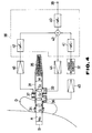
- FIG. 4 Another embodiment of the earphone device of the present invention will be described with reference to Fig. 4.
- the earphone device is formed so that it has an inner diameter W which is substantially identical with the inner diameter W0 of the external auditory canal A.
- the earphone device comprises an acoustic tube 31 having an inner diameter W which is substantially identical with the inner diameter W0 of the external auditory canal A and which is provided with auricle mounting member 34 made of a material such as synthetic resin or rubber having an elasticity at one end thereof and with a sound absorbing member 35 such as felt at the other end thereof so that the other end becomes an acoustic non-reflection terminal, an earphone unit 33, an internal microphone unit 36 adjacent to the earphone unit 5 provided on the periphery of the acoustic tube 1, each having a vibration plate facing inward of the tube, a phase reversing circuit 32 which reverses the phase of an audio signal in the acoustic tube 31 supplied from the internal microphone unit 36 for outputting it as a relatively fed back signal, an external microphone unit 37 disposed externally of the acoustic tube 31, which picks up external noises for outputting an external noise signal and a mixing circuit 38 which is capable of mixing the inputted audio signal such as music signal reproduced from
- the mixing circuit 38 comprises a first variable gain control circuit 40 for variably changing the gain of the inputted audio signal, a second variable gain control circuit 41 for variably changing the gain of the negatively fed back signal, a third variable gain control circuit 42 for variably changing the gain of the external noise signal and an adder 43 for adding the output signals from the variable gain control circuits 40, 41 and 42.
- the acoustic tube 31 forms an earphone casing.
- the inner diameter W0 of the external auditory canal A and the sound absorbing member 35 is provided at the other end to provide the acoustic non-reflecting terminal so that the acoustic impedance of the acoustic tube 31 is made substantially identical with the impedance of the external auditory canal A. So called localization in head is thus prevented.
- the earphone unit 33 and the inner microphone unit 36 are mounted on the side of the acoustic tube 31 so that the respective plates are in parallel relationship and the section area S1 of the acoustic tube 31 is equal to those S2 and S3 of the mounting portions of the earphone unit 33 and the microphone unit 36.
- Input audio signal such as music signal which has been reproduced from a compact portable stereo cassette tape recorder is supplied from an input circuit 39 to an amplification circuit 44 via the first variable gain control circuit 40 and the adder 13 of the mixing circuit 38 and is amplified by the amplification circuit 44 and is supplied to the earphone unit 33.
- the earphone unit 33 electro-acoustically converts the output signal from the amplification circuit 41 for providing reproduced sound.
- the sound provided by the earphone unit 33 transmits to the eardrum via the external auditory canal A and is picked up by the internal microphone unit 36.
- the sound which is picked up by the internal microphone unit 36 is supplied as audio signal to the phase reversing circuit 32 via the amplification circuit 45.
- the phase reversing circuit 32 reverses the phase of the audio signal supplied from the amplification circuit 45.
- the output signal from the phase reversing circuit 32 is supplied as negatively fed back signal having a phase opposite to that of the audio signal to the adder 43 via the second variable gain control circuit 41.
- the external microphone unit 37 picks up the external noise transmitting through the auditory canal A.
- the external noise signal obtained by picking up the external noise by the external microphone unit 37 is amplified by the amplification circuit 46 and is supplied to the adder 43 via the third variable gain control circuit 42.
- the adder 43 adds the inputted audio signal, the negatively fed back signal, and the external noise signal with each other.
- the added signal is supplied to the earphone unit 33 via the amplification circuit 44.
- the earphone unit 33 converts the output signals supplied from the amplification circuit 44 into audio signal for providing sounds.
- the earphone device of this embodiment is capable of controlling the mixing ratio of the input audio signal, the negatively fed back signal and the external noise signal which are added with each other in the adder 33 as mentioned above by means of the variable gain control circuits 40, 41 and 42.
- the gain of the external noise signal is adjusted to a low value or zero by the third variable gain control circuit 42.
- the gains of the input audio signal and the negatively fed back signal are adjusted to desired magnitudes by the first and second variable gain control circuits 40 and 41. Therefore, excellent reproduced sound having less noises can be listened.
- the gains of the input audio signal and the negatively fed back signal are not adjusted or adjusted to low values or zero and the gain of the external noise is increased by adjusting third variable gain control circuit 42, the gain of which has been a low value or zero.
- the external emergency information and the human voices can be listened while the earphone device is worn, that is, without removing the earphone device from the ear.
- the earphone device can be used as a so-called ear plug by turning off the first variable gain control circuit 40 so that the external noises reaching at the eardrum B are canceled by the negative feed back loop to provide a substantially silent condition. Also in this case, external sounds can be listened while the earphone device is worn by adjusting the gain of the external noise signal by the third variable gain control circuit 42.
- Adjustment of the gains of the variable gain control circuits 40, 41 and 42 can be achieved by operation of switches or knobs.
Landscapes
- Acoustics & Sound (AREA)
- Physics & Mathematics (AREA)
- Engineering & Computer Science (AREA)
- Health & Medical Sciences (AREA)
- Multimedia (AREA)
- General Health & Medical Sciences (AREA)
- Life Sciences & Earth Sciences (AREA)
- Signal Processing (AREA)
- Otolaryngology (AREA)
- Heart & Thoracic Surgery (AREA)
- Vascular Medicine (AREA)
- Animal Behavior & Ethology (AREA)
- Biomedical Technology (AREA)
- Public Health (AREA)
- Veterinary Medicine (AREA)
- Psychology (AREA)
- Biophysics (AREA)
- Audiology, Speech & Language Pathology (AREA)
- Headphones And Earphones (AREA)
- Circuit For Audible Band Transducer (AREA)
- Soundproofing, Sound Blocking, And Sound Damping (AREA)
Abstract
Applications Claiming Priority (5)
| Application Number | Priority Date | Filing Date | Title |
|---|---|---|---|
| JP2008509A JP2778173B2 (ja) | 1990-01-19 | 1990-01-19 | 騒音低減装置 |
| JP8509/90 | 1990-01-19 | ||
| JP8510/90 | 1990-01-19 | ||
| JP2008510A JP2778174B2 (ja) | 1990-01-19 | 1990-01-19 | イヤホン装置 |
| PCT/JP1991/000058 WO1991011078A1 (fr) | 1990-01-19 | 1991-01-18 | Casque a deux ecouteurs |
Publications (3)
| Publication Number | Publication Date |
|---|---|
| EP0464220A1 true EP0464220A1 (fr) | 1992-01-08 |
| EP0464220A4 EP0464220A4 (en) | 1992-10-21 |
| EP0464220B1 EP0464220B1 (fr) | 1995-09-27 |
Family
ID=26343033
Family Applications (1)
| Application Number | Title | Priority Date | Filing Date |
|---|---|---|---|
| EP91902743A Expired - Lifetime EP0464220B1 (fr) | 1990-01-19 | 1991-01-18 | Casque a deux ecouteurs |
Country Status (4)
| Country | Link |
|---|---|
| EP (1) | EP0464220B1 (fr) |
| KR (1) | KR100231219B1 (fr) |
| DE (1) | DE69113333T2 (fr) |
| WO (1) | WO1991011078A1 (fr) |
Cited By (4)
| Publication number | Priority date | Publication date | Assignee | Title |
|---|---|---|---|---|
| GB2436657A (en) * | 2006-04-01 | 2007-10-03 | Sonaptic Ltd | Ambient noise-reduction system |
| GB2438910A (en) * | 2006-06-09 | 2007-12-12 | Cotron Corp | Earphone with a sound guiding tube |
| EP2187654A4 (fr) * | 2007-09-07 | 2012-08-15 | Pioneer Corp | Écouteur |
| CN107155406A (zh) * | 2014-10-31 | 2017-09-12 | 索尼公司 | 声学换能器 |
Families Citing this family (2)
| Publication number | Priority date | Publication date | Assignee | Title |
|---|---|---|---|---|
| JP5401760B2 (ja) * | 2007-02-05 | 2014-01-29 | ソニー株式会社 | ヘッドフォン装置、音声再生システム、音声再生方法 |
| FI20155478A7 (fi) | 2015-06-18 | 2016-12-19 | Hefio Oy | Kuuloke akustiselle lähteelle ja kuormanmallinnus |
Family Cites Families (7)
| Publication number | Priority date | Publication date | Assignee | Title |
|---|---|---|---|---|
| JPS55165574U (fr) * | 1979-05-15 | 1980-11-28 | ||
| JPS5756083U (fr) * | 1980-09-17 | 1982-04-01 | ||
| JPS609397U (ja) * | 1983-06-29 | 1985-01-22 | 高橋 伸介 | 前面から質の良い音を聞くヘツドホ−ン |
| JP2726654B2 (ja) * | 1984-04-13 | 1998-03-11 | ボーズ・コーポレーション | ヘッドホーン装置 |
| JPS6180997A (ja) * | 1984-09-27 | 1986-04-24 | Nec Corp | 音量調節器付き拡声装置 |
| CA1299725C (fr) * | 1987-07-20 | 1992-04-28 | Robert Christopher Twiney | Systeme d'insonorisation |
| CA1336295C (fr) * | 1988-09-21 | 1995-07-11 | Masayoshi Miura | Appareil de reproduction de sons |
-
1991
- 1991-01-18 WO PCT/JP1991/000058 patent/WO1991011078A1/fr not_active Ceased
- 1991-01-18 EP EP91902743A patent/EP0464220B1/fr not_active Expired - Lifetime
- 1991-01-18 KR KR1019910701122A patent/KR100231219B1/ko not_active Expired - Lifetime
- 1991-01-18 DE DE69113333T patent/DE69113333T2/de not_active Expired - Lifetime
Cited By (8)
| Publication number | Priority date | Publication date | Assignee | Title |
|---|---|---|---|---|
| GB2436657A (en) * | 2006-04-01 | 2007-10-03 | Sonaptic Ltd | Ambient noise-reduction system |
| GB2436657B (en) * | 2006-04-01 | 2011-10-26 | Sonaptic Ltd | Ambient noise-reduction control system |
| GB2438910A (en) * | 2006-06-09 | 2007-12-12 | Cotron Corp | Earphone with a sound guiding tube |
| US7697710B2 (en) | 2006-06-09 | 2010-04-13 | Cotron Corporation | Earphone with a sound guiding tube |
| GB2438910B (en) * | 2006-06-09 | 2011-06-22 | Cotron Corp | Earphone with a sound guiding tube |
| EP2187654A4 (fr) * | 2007-09-07 | 2012-08-15 | Pioneer Corp | Écouteur |
| CN107155406A (zh) * | 2014-10-31 | 2017-09-12 | 索尼公司 | 声学换能器 |
| EP3214849A4 (fr) * | 2014-10-31 | 2018-04-18 | Sony Corporation | Dispositif transducteur acoustique |
Also Published As
| Publication number | Publication date |
|---|---|
| KR100231219B1 (ko) | 1999-11-15 |
| KR920702174A (ko) | 1992-08-12 |
| EP0464220B1 (fr) | 1995-09-27 |
| DE69113333T2 (de) | 1996-03-07 |
| WO1991011078A1 (fr) | 1991-07-25 |
| DE69113333D1 (de) | 1995-11-02 |
| EP0464220A4 (en) | 1992-10-21 |
Similar Documents
| Publication | Publication Date | Title |
|---|---|---|
| US5276740A (en) | Earphone device | |
| US5117461A (en) | Electroacoustic device for hearing needs including noise cancellation | |
| US5001763A (en) | Electroacoustic device for hearing needs including noise cancellation | |
| KR940005040B1 (ko) | 소음 저감장치 | |
| US4837832A (en) | Electronic hearing aid with gain control means for eliminating low frequency noise | |
| US5091954A (en) | Noise reducing receiver device | |
| US8144891B2 (en) | Earphone set | |
| JP2867461B2 (ja) | 騒音低減ヘッドホン | |
| JP2778173B2 (ja) | 騒音低減装置 | |
| DE69332020D1 (de) | Zweiteiliger kopfhörer | |
| HK1007618B (en) | Noise reducing receiver device | |
| JP3112268B2 (ja) | 騒音低減装置 | |
| EP0464220B1 (fr) | Casque a deux ecouteurs | |
| US20160173969A1 (en) | Multiple position earphone cable exit | |
| JP2778174B2 (ja) | イヤホン装置 | |
| JP3219113B2 (ja) | 小型収音再生装置 | |
| JP2822224B2 (ja) | 騒音低減ヘッドホン | |
| US20250301251A1 (en) | Hearing device and a method of adjusting a sidetone gain in a hearing device | |
| WO2023230789A1 (fr) | Dispositif auditif | |
| JPH02231900A (ja) | ヘッドホン装置 | |
| JPH02252399A (ja) | 可聴信号聴取装置 |
Legal Events
| Date | Code | Title | Description |
|---|---|---|---|
| PUAI | Public reference made under article 153(3) epc to a published international application that has entered the european phase |
Free format text: ORIGINAL CODE: 0009012 |
|
| 17P | Request for examination filed |
Effective date: 19910917 |
|
| AK | Designated contracting states |
Kind code of ref document: A1 Designated state(s): DE FR GB NL |
|
| A4 | Supplementary search report drawn up and despatched |
Effective date: 19920901 |
|
| AK | Designated contracting states |
Kind code of ref document: A4 Designated state(s): DE FR GB NL |
|
| 17Q | First examination report despatched |
Effective date: 19940614 |
|
| GRAA | (expected) grant |
Free format text: ORIGINAL CODE: 0009210 |
|
| AK | Designated contracting states |
Kind code of ref document: B1 Designated state(s): DE FR GB NL |
|
| REF | Corresponds to: |
Ref document number: 69113333 Country of ref document: DE Date of ref document: 19951102 |
|
| ET | Fr: translation filed | ||
| PLBE | No opposition filed within time limit |
Free format text: ORIGINAL CODE: 0009261 |
|
| STAA | Information on the status of an ep patent application or granted ep patent |
Free format text: STATUS: NO OPPOSITION FILED WITHIN TIME LIMIT |
|
| 26N | No opposition filed | ||
| REG | Reference to a national code |
Ref country code: GB Ref legal event code: IF02 |
|
| PGFP | Annual fee paid to national office [announced via postgrant information from national office to epo] |
Ref country code: GB Payment date: 20020116 Year of fee payment: 12 |
|
| PGFP | Annual fee paid to national office [announced via postgrant information from national office to epo] |
Ref country code: NL Payment date: 20020131 Year of fee payment: 12 |
|
| PG25 | Lapsed in a contracting state [announced via postgrant information from national office to epo] |
Ref country code: GB Free format text: LAPSE BECAUSE OF NON-PAYMENT OF DUE FEES Effective date: 20030118 |
|
| PG25 | Lapsed in a contracting state [announced via postgrant information from national office to epo] |
Ref country code: NL Free format text: LAPSE BECAUSE OF NON-PAYMENT OF DUE FEES Effective date: 20030801 |
|
| GBPC | Gb: european patent ceased through non-payment of renewal fee | ||
| NLV4 | Nl: lapsed or anulled due to non-payment of the annual fee |
Effective date: 20030801 |
|
| PGFP | Annual fee paid to national office [announced via postgrant information from national office to epo] |
Ref country code: FR Payment date: 20100208 Year of fee payment: 20 |
|
| PGFP | Annual fee paid to national office [announced via postgrant information from national office to epo] |
Ref country code: DE Payment date: 20100114 Year of fee payment: 20 |
|
| PG25 | Lapsed in a contracting state [announced via postgrant information from national office to epo] |
Ref country code: DE Free format text: LAPSE BECAUSE OF EXPIRATION OF PROTECTION Effective date: 20110118 |