EP0464722A2 - Leuchtstofflampe mit einem Fenster und Quetschdichtungen - Google Patents
Leuchtstofflampe mit einem Fenster und Quetschdichtungen Download PDFInfo
- Publication number
- EP0464722A2 EP0464722A2 EP91110787A EP91110787A EP0464722A2 EP 0464722 A2 EP0464722 A2 EP 0464722A2 EP 91110787 A EP91110787 A EP 91110787A EP 91110787 A EP91110787 A EP 91110787A EP 0464722 A2 EP0464722 A2 EP 0464722A2
- Authority
- EP
- European Patent Office
- Prior art keywords
- envelope
- fluorescent lamp
- aperture
- electrical leads
- lamp
- Prior art date
- Legal status (The legal status is an assumption and is not a legal conclusion. Google has not performed a legal analysis and makes no representation as to the accuracy of the status listed.)
- Granted
Links
Images
Classifications
-
- H—ELECTRICITY
- H01—ELECTRIC ELEMENTS
- H01J—ELECTRIC DISCHARGE TUBES OR DISCHARGE LAMPS
- H01J5/00—Details relating to vessels or to leading-in conductors common to two or more basic types of discharge tubes or lamps
- H01J5/50—Means forming part of the tube or lamps for the purpose of providing electrical connection to it
- H01J5/52—Means forming part of the tube or lamps for the purpose of providing electrical connection to it directly applied to or forming part of the vessel
-
- H—ELECTRICITY
- H01—ELECTRIC ELEMENTS
- H01J—ELECTRIC DISCHARGE TUBES OR DISCHARGE LAMPS
- H01J61/00—Gas-discharge or vapour-discharge lamps
- H01J61/02—Details
- H01J61/36—Seals between parts of vessels; Seals for leading-in conductors; Leading-in conductors
- H01J61/366—Seals for leading-in conductors
- H01J61/368—Pinched seals or analogous seals
Definitions
- This invention relates to fluorescent lamps and, more particularly, to miniature fluorescent lamps having press seals.
- the invention is particularly useful to facilitate orientation of an aperture in a miniature fluorescent lamp.
- a conventional fluorescent lamp includes a cylindrical tube having a uniform phosphor coating on its inner surface. Such a lamp emits light with a uniform cylindrical pattern. In some applications, such as backlighting of a display, it is desirable to provide a fluorescent lamp which emits light in a preferred direction.
- Fluorescent lamps having an aperture which extends axially along the length of the lamp envelope are well known.
- a reflective coating is applied to the inside surface of the lamp envelope prior to application of the phosphor coating so that substantially all the light generated by the lamp is directed through the aperture. Examples of aperture fluorescent lamps are disclosed in U.S. Patent No. 3,225,241 issued December 21, 1965 to Spencer et al, U.S. Patent No. 3,987,331 issued October 19, 1976 to Schreurs, U.S. Patent No.
- Arc discharge tubes and miniature incandescent lamps have been fabricated with press seals.
- a press seal the end of an arc tube or a lamp envelope is heated and is pressed together around the electrical leads which connect to the filament or electrode.
- An example of a baseless incandescent lamp, also referred to a wedge base lamp, which utilizes a press seal is disclosed in U.S. Patent No. 4,593,958 issued June 10, 1986 to Baba.
- so-called "twin-tube" fluorescent lamps which have a U-shaped lamp envelope, have utilized press seals.
- a fluorescent lamp comprising a light-transmissive envelope containing a fill material for supporting a low pressure discharge, the envelope having on its inside surface a phosphor coating, a filament in each end of the lamp envelope, and one or more electrical leads attached to each filament.
- the envelope includes at each end a press seal wherein opposite sides of the envelope are pressed together and deformed around the electrical leads to thereby seal the electrical leads to the envelope.
- the lamp typically has an aperture for directing light in a predetermined direction, and the press seal has a predetermined orientation relative to the aperture.
- the light-transmissive envelope is typically a cylindrical glass tube, and the aperture extends axially along its length.
- the press seal preferably includes a tubulation for exhausting and filling the envelope and flattened regions on each side of the tubulation.
- the electrical leads extend through and are sealed into the flattened regions.
- the flattened regions have a generally planar surfaces with a predetermined orientation relative to the aperture. In a preferred embodiment, the planar surfaces are oriented at about 90° relative to a line through the center of the aperture and the axis of the envelope.
- the electrical leads include external portions that can be formed along the planar surfaces of the flattened regions so that the press seal can be engaged in a mating socket. At least one of the flattened regions can be provided with a projection or a detent for axial positioning of the lamp.
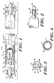
- FIGS. 1-4 A fluorescent lamp 10 in accordance with the present invention is shown in FIGS. 1-4.
- the lamp 10 is a subminiature aperture fluorescent lamp having a generally cylindrical light-transmissive lamp envelope 12.
- the envelope 12 is typically fabricated of soda lime glass and by way of example can have an outside diameter on the order of about 0.18 inch to 0.27 inch and a length in the range of 4-20 inches.
- a filament 14 is mounted in each end of envelope 12. Electrical leads 16 and 18 are connected to opposite ends of filament 14 and extend through a press seal 20. The opposite end of the lamp 10 is constructed in the same manner and includes a press seal 22.
- a mercury dispenser 24 is attached to electrical lead 16.
- the lamp 10 contains a fill material including mercury supplied from dispenser 24 and a rare gas such as argon.
- the lamp 10 can utilize either a hot cathode or a cold cathode configuration, as known in the art.
- the leads 16 and 18 are connected so that a current is supplied through each filament 14.
- each filament 14 may have two leads connected to it, but only one electrical connection is required. Thus, one lead can be cut off, or the leads can be connected together.
- a coating 30 is applied to the inside surface of envelope 12.
- the layer 30 includes a reflective layer and a phosphor layer.
- the reflective layer is first applied to the inside surface of envelope 12 and then the phosphor layer is applied over the reflective layer.
- the reflective layer has a reflective inside surface.
- An aperture 34 is formed in the layer 30 to direct light from the lamp 10 in a preferred direction. As best shown in FIG. 1, the aperture 34 extends axially along a major portion of length of envelope 12 and has a uniform width. The width of aperture 34 depends on the desired radiation pattern from the lamp 10. The reflective layer insures that light emitted from the lamp 10 is directed through aperture 34. In an alternative configuration, the reflective layer is removed in aperture 34 but a phosphor layer is applied to the entire inner surface of tube 12.
- the aperture 34 and the reflective layer are omitted.
- the phosphor layer is uniformly applied to the inside surface of envelope 12, and the lamp provides a uniform cylindrical radiation pattern.
- the press seals 20 and 22 each include a tubulation 40 generally positioned on an axis 42 of envelope 12 and flattened regions 44 and 46 on opposite sides of tubulation 40.
- Electrical lead 16 extends through and is sealed into flattened region 44
- electrical lead 18 extends through and is sealed into flattened region 46.
- Flattened regions 44 and 46 include generally flat surfaces 44a and 46a (FIG. 3), respectively, which are used for orientation of aperture 34 as described hereinafter.
- the surfaces 44a and 46a are oriented at 90° with respect to a line drawn through the center of aperture 34 and the axis 42 of the envelope 12.
- the electrical leads 16 and 18 extend from the end of press seal 20 for connection of the filament 14 to a source of electrical energy.
- the leads 16 and 18 extend from the end of lamp 10 parallel to axis 42 and can be connected to leads from the electrical source in any convenient manner, such as by crimping.
- the leads 16 and 18 are bent on opposite sides of press seal 20 and extend along the surfaces of flattened regions 44 and 46 respectively.
- the end of the lamp 10 can be inserted into a socket similar to the sockets that are utilized for automotive wedge base lamps.
- one of the leads 16, 18 can be cut off in the case of a cold cathode lamp.
- the press seals 20 and 22 can be provided with means for positioning the lamp 10 along axis 42.
- the positioning means can comprise one or more detents 50 formed in the press seals 20 and 22.
- the detents 50 comprise a depression or groove in flattened regions 44 and 46. The groove is oriented with its sides perpendicular to the axis 42 of envelope 12.
- one detent 50 is provided on each side of each press seal.
- a detent 50 is located on the front of flattened region 46 and a detent (not shown) is located on the back of flattened region 44.
- the detents 50 can be replaced with projections which engage corresponding detents in the mounting structure.
- the desired coating 30 is applied to the inside surface of envelope 12 prior to formation of press seals 20 and 22.
- the coating 30 includes a phosphor layer and, when the lamp 10 is an aperture fluorescent lamp, includes a reflective layer as described above.
- the layers are applied according to well-known techniques.
- the aperture 34 is formed in the coating 30 by scraping the inside surface of tube 12.
- a scraping tool is moved axially along the length of envelope 12 to form aperture 34.
- the scraping tool is retained against the inside surface of envelope 12 by a magnet located outside envelope 12 to insure formation of a uniform, cleanly-scraped aperture.
- a preferred technique for scraping aperture 34 is described in detail in copending application Serial No. (Attorney's Docket No. G0240/7129) filed concurrently herewith and assigned to the assignee of the present application, which application is hereby incorporated by reference.
- filament assemblies including filament 14, leads 16 and 18 and mercury dispenser 24 are positioned at opposite ends of envelope 12.
- the envelope 12 is heated to a temperature on the order of about 900°C sufficient to soften the material of envelope 12.
- An optical technique is utilized to orient the aperture 34 relative to a press sealing tool.
- an image processing system including a video camera and a computer, is utilized to perform orientation in accordance with well-known image processing techniques.
- the envelope 12 is rotated by a friction wheel, and the camera identifies edges 34a and 34b of aperture 34.
- the computer calculates the orientation of the center of aperture 34 and applies an appropriate signal to a motor which drives the friction wheel.
- the friction wheel rotates the envelope 12 about its axis until the center of aperture 34 has the desired orientation relative to the press seal tool.
- Press seal jaws having the shape of the press seal 20 are brought together against opposite sides of the heated envelope 12 to thereby form press seals 20 and 22.
- the leads 16 and 18 are preferably fabricated of nickel-iron.
- the tubulation 40 at each end of the lamp 10 remains open after press sealing.
- the envelope 12 is exhausted and backfilled with a gas such as argon at a pressure on the order of 1-40 torr.
- the tubulations are then sealed, and the leads 16 and 18 are bent to the desired configuration, if necessary.
- the aperture 34 can be oriented with respect to press seal surfaces 44a and 46a to an accuracy of 1.5°.
- prior art aperture fluorescent lamps provided orientation accuracies on the order of about 5°.
Landscapes
- Vessels And Coating Films For Discharge Lamps (AREA)
Applications Claiming Priority (2)
| Application Number | Priority Date | Filing Date | Title |
|---|---|---|---|
| US07/547,984 US5142191A (en) | 1990-07-03 | 1990-07-03 | Aperture fluorescent lamp with press seal configuration |
| US547984 | 1990-07-03 |
Publications (3)
| Publication Number | Publication Date |
|---|---|
| EP0464722A2 true EP0464722A2 (de) | 1992-01-08 |
| EP0464722A3 EP0464722A3 (en) | 1992-10-28 |
| EP0464722B1 EP0464722B1 (de) | 1996-12-11 |
Family
ID=24186957
Family Applications (1)
| Application Number | Title | Priority Date | Filing Date |
|---|---|---|---|
| EP91110787A Expired - Lifetime EP0464722B1 (de) | 1990-07-03 | 1991-06-28 | Leuchtstofflampe mit einem Fenster und Quetschdichtungen |
Country Status (4)
| Country | Link |
|---|---|
| US (1) | US5142191A (de) |
| EP (1) | EP0464722B1 (de) |
| JP (1) | JPH0789479B2 (de) |
| DE (1) | DE69123498T2 (de) |
Families Citing this family (8)
| Publication number | Priority date | Publication date | Assignee | Title |
|---|---|---|---|---|
| US5296780A (en) * | 1992-03-20 | 1994-03-22 | Gte Products Corporation | Arc discharge lamp having cementless right-angle base members |
| DE9305977U1 (de) * | 1993-04-20 | 1993-08-12 | Patent-Treuhand-Gesellschaft für elektrische Glühlampen mbH, 81543 München | Zweiseitig gesockelte Niederdruckentladungslampe |
| SE513425C2 (sv) | 1997-10-02 | 2000-09-11 | Auralight Ab | Lysrör innefattande två diametralt belägna diffusorskikt |
| EP1014158A1 (de) * | 1998-12-22 | 2000-06-28 | Mannesmann VDO Aktiengesellschaft | Anzeigeeinrichtung |
| US6400097B1 (en) * | 2001-10-18 | 2002-06-04 | General Electric Company | Low wattage fluorescent lamp |
| US6921878B2 (en) * | 2003-02-04 | 2005-07-26 | Ado Enterprise Co., Ltd. | Warmth-keeping structure of cold cathode lamp |
| US20070103080A1 (en) * | 2005-11-09 | 2007-05-10 | Zoltan Bako | Glass sealing and electric lamps with such sealing |
| US20080106177A1 (en) * | 2006-11-07 | 2008-05-08 | Jansma Jon B | Fluorescent lamp utilizing a partial barrier coating resulting in assymetric or oriented light output and process for same |
Family Cites Families (16)
| Publication number | Priority date | Publication date | Assignee | Title |
|---|---|---|---|---|
| US2162546A (en) * | 1934-07-09 | 1939-06-13 | Gen Electric | Gaseous electric discharge device |
| US2094668A (en) * | 1935-03-13 | 1937-10-05 | Gen Electric | Electric metal vapor lighting tube |
| US2322421A (en) * | 1938-12-22 | 1943-06-22 | Sylvania Electric Prod | Electric discharge lamp |
| US3115309A (en) * | 1959-07-09 | 1963-12-24 | Sylvania Electric Prod | Aperture fluorescent lamp |
| US3225241A (en) * | 1959-07-09 | 1965-12-21 | Sylvania Electric Prod | Aperture fluorescent lamp |
| US3067351A (en) * | 1960-01-04 | 1962-12-04 | Sylvania Electric Prod | Aperture fluorescent lamp |
| US3012168A (en) * | 1960-03-23 | 1961-12-05 | Sylvania Electric Prod | Fluorescent lamp |
| US3275872A (en) * | 1963-07-12 | 1966-09-27 | Gen Electric | Reflector fluorescent lamp |
| US3717781A (en) * | 1969-09-19 | 1973-02-20 | Sylvania Electric Prod | Aperture fluorescent lamp having uniform surface brightness |
| US3886396A (en) * | 1971-10-10 | 1975-05-27 | Gen Electric | Fluorescent lamp with protective coating |
| US3987331A (en) * | 1975-03-24 | 1976-10-19 | Gte Sylvania Incorporated | Ultraviolet emitting fluorescent lamp having internal reflector film |
| JPS5740851A (en) * | 1980-08-22 | 1982-03-06 | Toshiba Corp | Metallic vapor discharge lamp and its manufacturing method |
| DE3112878A1 (de) * | 1981-03-31 | 1982-10-14 | Patent-Treuhand-Gesellschaft für elektrische Glühlampen mbH, 8000 München | Quecksilberdampf-niederdruckentladungslampe und verfahren zur herstellung |
| US4593958A (en) * | 1984-05-04 | 1986-06-10 | Kabushiki Kaisha Toshiba | Socket for baseless lamp |
| US4692661A (en) * | 1986-02-18 | 1987-09-08 | Gte Products Corporation | Fluorescent lamp with static magnetic field generating means |
| JPS63186046U (de) * | 1987-05-25 | 1988-11-29 |
-
1990
- 1990-07-03 US US07/547,984 patent/US5142191A/en not_active Expired - Fee Related
-
1991
- 1991-06-28 DE DE69123498T patent/DE69123498T2/de not_active Expired - Lifetime
- 1991-06-28 EP EP91110787A patent/EP0464722B1/de not_active Expired - Lifetime
- 1991-07-02 JP JP3187037A patent/JPH0789479B2/ja not_active Expired - Lifetime
Also Published As
| Publication number | Publication date |
|---|---|
| JPH04229944A (ja) | 1992-08-19 |
| DE69123498T2 (de) | 1997-06-26 |
| US5142191A (en) | 1992-08-25 |
| JPH0789479B2 (ja) | 1995-09-27 |
| DE69123498D1 (de) | 1997-01-23 |
| EP0464722A3 (en) | 1992-10-28 |
| EP0464722B1 (de) | 1996-12-11 |
Similar Documents
| Publication | Publication Date | Title |
|---|---|---|
| US5086249A (en) | Compact discharge lamp unit and method for manufacturing same | |
| US3622832A (en) | Interchangeable tungsten halogen lamp | |
| US5142191A (en) | Aperture fluorescent lamp with press seal configuration | |
| US5210461A (en) | Arc discharge lamp containing mechanism for extinguishing arc at end-of-life | |
| JP3078029U (ja) | 片側にソケットを備えたハロゲンランプ | |
| EP0540019A1 (de) | Montage für Metallhalogenid-Bogenentladungslampe | |
| EP0156384B1 (de) | Elektrodenaufstellung und Kapselentwurf für einseitig gesockelte Niederleistungsmetallhalogenidlampen | |
| EP0903772B1 (de) | Gleichstrom-Entladungslampe und Lichtquelle mit, unmittelbar an der Enladungslampe angebrachten Reflektor | |
| EP0585447B1 (de) | Kittlos gesockelte gasentladungslampe mit rechtwinkliger halterung | |
| EP0136685A2 (de) | Kompakte Leuchtstofflampe | |
| US4560357A (en) | Method for sealing arc discharge lamps | |
| US5896003A (en) | Compact fluorescent lamp and method for manufacturing the same | |
| US5276379A (en) | Arc discharge lamp having cementless base members | |
| EP0033652B1 (de) | Elektrische Niederdruckentladungslampe | |
| US5757134A (en) | Mica heat shield for high intensity discharge lamp | |
| JP2823709B2 (ja) | ランプアセンブリイ | |
| EP0127475A1 (de) | Zweiseitig gesockelte Kompakt-Leuchtstofflampe | |
| JP3167355B2 (ja) | シングルエンド2重ランプ | |
| KR100382059B1 (ko) | 메탈할라이드램프제조방법 | |
| JPH10214595A (ja) | セラミックス放電ランプ,ランプ装置,点灯装置および液晶プロジェクター | |
| JPH0524118Y2 (de) | ||
| JPH0817091B2 (ja) | 低圧放電灯 | |
| JPH0574420A (ja) | 金属蒸気放電灯 | |
| JP3348323B2 (ja) | 放電ランプおよび照明装置 | |
| JPH03210751A (ja) | 小形偏平蛍光ランプおよび照明装置 |
Legal Events
| Date | Code | Title | Description |
|---|---|---|---|
| PUAI | Public reference made under article 153(3) epc to a published international application that has entered the european phase |
Free format text: ORIGINAL CODE: 0009012 |
|
| 17P | Request for examination filed |
Effective date: 19910720 |
|
| AK | Designated contracting states |
Kind code of ref document: A2 Designated state(s): DE FR GB IT NL |
|
| PUAL | Search report despatched |
Free format text: ORIGINAL CODE: 0009013 |
|
| AK | Designated contracting states |
Kind code of ref document: A3 Designated state(s): DE FR GB IT NL |
|
| 17Q | First examination report despatched |
Effective date: 19940629 |
|
| GRAH | Despatch of communication of intention to grant a patent |
Free format text: ORIGINAL CODE: EPIDOS IGRA |
|
| GRAH | Despatch of communication of intention to grant a patent |
Free format text: ORIGINAL CODE: EPIDOS IGRA |
|
| GRAA | (expected) grant |
Free format text: ORIGINAL CODE: 0009210 |
|
| AK | Designated contracting states |
Kind code of ref document: B1 Designated state(s): DE FR GB IT NL |
|
| PG25 | Lapsed in a contracting state [announced via postgrant information from national office to epo] |
Ref country code: IT Free format text: LAPSE BECAUSE OF FAILURE TO SUBMIT A TRANSLATION OF THE DESCRIPTION OR TO PAY THE FEE WITHIN THE PRE;WARNING: LAPSES OF ITALIAN PATENTS WITH EFFECTIVE DATE BEFORE 2007 MAY HAVE OCCURRED AT ANY TIME BEFORE 2007. THE CORRECT EFFECTIVE DATE MAY BE DIFFERENT FROM THE ONE RECORDED.SCRIBED TIME-LIMIT Effective date: 19961211 |
|
| REF | Corresponds to: |
Ref document number: 69123498 Country of ref document: DE Date of ref document: 19970123 |
|
| ET | Fr: translation filed | ||
| PLBE | No opposition filed within time limit |
Free format text: ORIGINAL CODE: 0009261 |
|
| STAA | Information on the status of an ep patent application or granted ep patent |
Free format text: STATUS: NO OPPOSITION FILED WITHIN TIME LIMIT |
|
| 26N | No opposition filed | ||
| PGFP | Annual fee paid to national office [announced via postgrant information from national office to epo] |
Ref country code: DE Payment date: 19990828 Year of fee payment: 9 |
|
| PGFP | Annual fee paid to national office [announced via postgrant information from national office to epo] |
Ref country code: GB Payment date: 20000622 Year of fee payment: 10 |
|
| PGFP | Annual fee paid to national office [announced via postgrant information from national office to epo] |
Ref country code: FR Payment date: 20000630 Year of fee payment: 10 Ref country code: NL Payment date: 20000630 Year of fee payment: 10 |
|
| PG25 | Lapsed in a contracting state [announced via postgrant information from national office to epo] |
Ref country code: DE Free format text: LAPSE BECAUSE OF THE APPLICANT RENOUNCES Effective date: 20001021 |
|
| PG25 | Lapsed in a contracting state [announced via postgrant information from national office to epo] |
Ref country code: GB Free format text: LAPSE BECAUSE OF NON-PAYMENT OF DUE FEES Effective date: 20010628 |
|
| PG25 | Lapsed in a contracting state [announced via postgrant information from national office to epo] |
Ref country code: NL Free format text: LAPSE BECAUSE OF NON-PAYMENT OF DUE FEES Effective date: 20020101 |
|
| GBPC | Gb: european patent ceased through non-payment of renewal fee |
Effective date: 20010628 |
|
| PG25 | Lapsed in a contracting state [announced via postgrant information from national office to epo] |
Ref country code: FR Free format text: LAPSE BECAUSE OF NON-PAYMENT OF DUE FEES Effective date: 20020228 |
|
| NLV4 | Nl: lapsed or anulled due to non-payment of the annual fee |
Effective date: 20020101 |