EP0465260B1 - Méthode et appareil de nettoyage d'une plaque à orifice de gicleurs d'encre - Google Patents
Méthode et appareil de nettoyage d'une plaque à orifice de gicleurs d'encre Download PDFInfo
- Publication number
- EP0465260B1 EP0465260B1 EP91306107A EP91306107A EP0465260B1 EP 0465260 B1 EP0465260 B1 EP 0465260B1 EP 91306107 A EP91306107 A EP 91306107A EP 91306107 A EP91306107 A EP 91306107A EP 0465260 B1 EP0465260 B1 EP 0465260B1
- Authority
- EP
- European Patent Office
- Prior art keywords
- printhead
- wiper
- recited
- blades
- carriage
- Prior art date
- Legal status (The legal status is an assumption and is not a legal conclusion. Google has not performed a legal analysis and makes no representation as to the accuracy of the status listed.)
- Expired - Lifetime
Links
- 238000004140 cleaning Methods 0.000 title claims description 28
- 238000000034 method Methods 0.000 title description 16
- 239000000356 contaminant Substances 0.000 claims description 40
- 230000033001 locomotion Effects 0.000 claims description 33
- 238000007639 printing Methods 0.000 claims description 22
- 230000004044 response Effects 0.000 claims description 4
- 230000002745 absorbent Effects 0.000 claims description 3
- 239000002250 absorbent Substances 0.000 claims description 3
- 230000008878 coupling Effects 0.000 claims 2
- 238000010168 coupling process Methods 0.000 claims 2
- 238000005859 coupling reaction Methods 0.000 claims 2
- 239000000976 ink Substances 0.000 description 96
- 230000007246 mechanism Effects 0.000 description 43
- 238000006073 displacement reaction Methods 0.000 description 21
- 230000009471 action Effects 0.000 description 12
- 238000009736 wetting Methods 0.000 description 9
- 239000000428 dust Substances 0.000 description 8
- 230000008569 process Effects 0.000 description 7
- 230000007547 defect Effects 0.000 description 6
- 239000000463 material Substances 0.000 description 6
- 230000006870 function Effects 0.000 description 5
- 238000005201 scrubbing Methods 0.000 description 5
- 239000007787 solid Substances 0.000 description 5
- 238000011109 contamination Methods 0.000 description 4
- 238000012864 cross contamination Methods 0.000 description 4
- 238000012360 testing method Methods 0.000 description 4
- 239000003086 colorant Substances 0.000 description 3
- 238000013461 design Methods 0.000 description 3
- 230000003993 interaction Effects 0.000 description 3
- 230000001788 irregular Effects 0.000 description 3
- 230000000670 limiting effect Effects 0.000 description 3
- 239000012858 resilient material Substances 0.000 description 3
- 229920002943 EPDM rubber Polymers 0.000 description 2
- 229920000459 Nitrile rubber Polymers 0.000 description 2
- 238000009825 accumulation Methods 0.000 description 2
- 238000013459 approach Methods 0.000 description 2
- 238000011161 development Methods 0.000 description 2
- 230000018109 developmental process Effects 0.000 description 2
- 238000010304 firing Methods 0.000 description 2
- 230000002452 interceptive effect Effects 0.000 description 2
- 230000007935 neutral effect Effects 0.000 description 2
- 230000036961 partial effect Effects 0.000 description 2
- 239000004033 plastic Substances 0.000 description 2
- 230000000717 retained effect Effects 0.000 description 2
- 238000007790 scraping Methods 0.000 description 2
- 238000007789 sealing Methods 0.000 description 2
- 239000011358 absorbing material Substances 0.000 description 1
- 230000004323 axial length Effects 0.000 description 1
- 230000008901 benefit Effects 0.000 description 1
- 230000008859 change Effects 0.000 description 1
- 230000000881 depressing effect Effects 0.000 description 1
- 230000000694 effects Effects 0.000 description 1
- 238000005516 engineering process Methods 0.000 description 1
- 239000000835 fiber Substances 0.000 description 1
- 230000005484 gravity Effects 0.000 description 1
- 230000006872 improvement Effects 0.000 description 1
- 230000000977 initiatory effect Effects 0.000 description 1
- 238000004519 manufacturing process Methods 0.000 description 1
- 230000013011 mating Effects 0.000 description 1
- 238000012986 modification Methods 0.000 description 1
- 230000004048 modification Effects 0.000 description 1
- 230000000737 periodic effect Effects 0.000 description 1
- 230000037452 priming Effects 0.000 description 1
- 238000012545 processing Methods 0.000 description 1
- 230000002035 prolonged effect Effects 0.000 description 1
- 238000009877 rendering Methods 0.000 description 1
- 230000000284 resting effect Effects 0.000 description 1
- 230000002441 reversible effect Effects 0.000 description 1
- 239000007921 spray Substances 0.000 description 1
- 229920003051 synthetic elastomer Polymers 0.000 description 1
- 239000005061 synthetic rubber Substances 0.000 description 1
Images


Classifications
-
- B—PERFORMING OPERATIONS; TRANSPORTING
- B41—PRINTING; LINING MACHINES; TYPEWRITERS; STAMPS
- B41J—TYPEWRITERS; SELECTIVE PRINTING MECHANISMS, i.e. MECHANISMS PRINTING OTHERWISE THAN FROM A FORME; CORRECTION OF TYPOGRAPHICAL ERRORS
- B41J2/00—Typewriters or selective printing mechanisms characterised by the printing or marking process for which they are designed
- B41J2/005—Typewriters or selective printing mechanisms characterised by the printing or marking process for which they are designed characterised by bringing liquid or particles selectively into contact with a printing material
- B41J2/01—Ink jet
- B41J2/135—Nozzles
- B41J2/165—Prevention or detection of nozzle clogging, e.g. cleaning, capping or moistening for nozzles
- B41J2/16517—Cleaning of print head nozzles
- B41J2/16535—Cleaning of print head nozzles using wiping constructions
- B41J2/16544—Constructions for the positioning of wipers
-
- B—PERFORMING OPERATIONS; TRANSPORTING
- B41—PRINTING; LINING MACHINES; TYPEWRITERS; STAMPS
- B41J—TYPEWRITERS; SELECTIVE PRINTING MECHANISMS, i.e. MECHANISMS PRINTING OTHERWISE THAN FROM A FORME; CORRECTION OF TYPOGRAPHICAL ERRORS
- B41J2/00—Typewriters or selective printing mechanisms characterised by the printing or marking process for which they are designed
- B41J2/005—Typewriters or selective printing mechanisms characterised by the printing or marking process for which they are designed characterised by bringing liquid or particles selectively into contact with a printing material
- B41J2/01—Ink jet
- B41J2/135—Nozzles
- B41J2/165—Prevention or detection of nozzle clogging, e.g. cleaning, capping or moistening for nozzles
- B41J2/16517—Cleaning of print head nozzles
- B41J2/16535—Cleaning of print head nozzles using wiping constructions
- B41J2/16541—Means to remove deposits from wipers or scrapers
-
- B—PERFORMING OPERATIONS; TRANSPORTING
- B41—PRINTING; LINING MACHINES; TYPEWRITERS; STAMPS
- B41J—TYPEWRITERS; SELECTIVE PRINTING MECHANISMS, i.e. MECHANISMS PRINTING OTHERWISE THAN FROM A FORME; CORRECTION OF TYPOGRAPHICAL ERRORS
- B41J2/00—Typewriters or selective printing mechanisms characterised by the printing or marking process for which they are designed
- B41J2/005—Typewriters or selective printing mechanisms characterised by the printing or marking process for which they are designed characterised by bringing liquid or particles selectively into contact with a printing material
- B41J2/01—Ink jet
- B41J2/135—Nozzles
- B41J2/165—Prevention or detection of nozzle clogging, e.g. cleaning, capping or moistening for nozzles
- B41J2/16517—Cleaning of print head nozzles
- B41J2002/16576—Cleaning means pushed or actuated by print head movement
Definitions
- This invention relates generally to ink-jet printers and printheads, and more particularly to a method and apparatus for automatic cleaning of ink-jet printheads.
- the orifice plate of the printhead of an ink-jet printer tends to pick up contaminants, such as paper dust, and the like, during the printing process. Such contaminants adhere to the orifice plate either because of the presence of ink on the printhead, or because of electrostatic charges.
- excess dried ink can accumulate around the printhead, particularly if all the ink is not pumped out of the printhead. The accumulation of either ink or other contaminants can impair the quality of the output by interfering with the proper application of ink to the printing medium.
- each printhead may have different nozzles which each expel different colors. If ink accumulates on the orifice plate, mixing of different colored inks can result during use.
- the quality of the resulting printed product can be affected. For these reasons, it is desirable to clear the printhead orifice plate of such contaminants and ink on a routine basis to prevent the build up thereof. Furthermore, the nozzles of an ink-jet printer can clog, particularly if the pens are left uncapped in an office environment.
- Patent Abstracts of Japan, Vol. 12, No. 126 (M-687) [2973], 19th April 1988 and JP-A-62251146 describes an ink jet printer incorporating means to wipe a plurality of recording heads without causing mixing of colors.
- the wiping means comprises a plurality of cleaning brushes corresponding to the respective plurality of printer heads and provided along an endless belt. The belt is driven such that each brush cleans a different printer head in sequence.
- an object of the present invention to provide a wiper for an ink-jet printer having both a color printhead and a black printhead for removal of contaminants without any mixing of the ink from the two printheads.
- the present invention provides an apparatus for cleaning first and second printheads disposed on a printhead carriage in an ink-jet printer comprising: a first wiper blade for wiping a first printhead; a second wiper blade for wiping a second printhead; means actuated in response to motion of the printhead carriage for selectively bringing said first wiper blade into wiping contact only with said first printhead, and for selectively bringing said second wiper blade into wiping contact only with said second printhead; and means for producing relative wiping motion between said first printhead and said first wiper blade and said second printhead and said second wiper blade.
- the invention comprises a wiper having a plurality of resilient blades extending outwardly from a central axis of rotation and means for indexing a selected blade into position for wiping.
- the desired cleansing is produced by dragging a selected printhead by movement of the printhead carriage across an associated stationary wiper blade.
- At least one blade is associated with each printhead. In a preferred embodiment, four blades are provided, two blades being dedicated to wiping the color printhead and two blades being dedicated to wiping the black printhead.
- the two different pairs of wiper blades have different lengths and their associated printhead has a correspondingly different printhead to paper spacing, so that the color and black printheads can be selectively wiped, without wiping of the other printhead. In this manner, mixing of the inks between the different printheads is avoided.
- the indexing mechanism typically comprises a lever arm which is actuable by movement of the printhead carriage, and which is associated with a ratcheting mechanism to permit indexing of the wiper in one direction only.
- a biasing spring returns the arm to its initial position for continued indexing during another pass of the printhead carriage.
- a cleaning apparatus for removal of contaminants from the wiper.
- the cleaning apparatus includes a series of scrapers disposed about the periphery of the wiper at a position spaced from the area in which the printhead orifice is wiped. As the wiper is indexed under normal circumstances, the wiper blades are dragged across the scrapers for removal of ink and other contaminants thereon.
- the wiping mechanism of the first embodiment can be used in either one of two modes.
- the printhead orifice plate of both the color printhead and the black printhead are both selectively wiped automatically at a preselected stage of the printing operation, for example, at the beginning of each page of text that is printed.
- the wiper is not wetted with expelled ink during or before the wiping process.
- the second mode involves the spitting of ink from the printheads onto the wiper blades to assist in rehydrating the dried ink disposed on the printhead orifice plate and a more prolonged and a repeated mechanical scrubbing process. This second mode is typically employed only when the user perceives a decrease in print quality and initiates the procedure manually.
- the wiper mechanism comprises a plurality of resilient blades, each having a plurality of wiping edges which can be rotated or indexed into position as needed.
- One blade is provided for each printhead to be wiped.
- each blade is thin and flexible and has an octagonal shape.
- Each blade may be indexed about an axis passing through the center of the octagon so that a fresh edge is presented in wiping relation with a printhead for each wiping sequence.
- each blade is indexed by a cam disposed on the printhead carriage which actuates a cam follower as the printhead carriage passes thereover.
- each blade As each blade is indexed, it passes through a blade cleaner which typically includes an absorbent material positioned in contact with the blade to wick away ink, as well as to wipe the blade clean.
- the blades are normally spaced below the printheads to avoid inadvertent contact when no wiping is desired.
- the blades When the printheads are disposed above their associated blades for wiping, the blades are raised into wiping contact.
- the blades are raised by rotating a shaft containing the blades in response to a movement of the printhead carriage.
- the second embodiment also includes the expelling of ink upon the wiper blades to allow rehydration of the dried ink to facilitate removal thereof.
- the ink is expelled upon an associated blade just prior to wiping to prevent excessive color mixing on the printhead orifice of the color printhead. This expelling of ink typically is followed by a series of scrubbing cycles by the wiper blades.
- the foregoing wiper apparatus permits selective wiping of each printhead by an associated blade when more than one printhead is disposed on a printhead carriage to prevent contamination of one printhead with the ink from another printhead.
- the foregoing apparatus and method facilitates the removal of dried ink from the orifice plates of the printheads and permits cleaning of the printheads without use of a vacuum pump.
- the particular mechanical configuration of the actuating system provides a simplified and dependable apparatus which is not subject to failure, and which can be simply and inexpensively assembled.
- FIG. 1 a typical ink-jet printer 10 will be described with which the wiper of this invention may be used.
- Ink-jet printer 10 is of the type in which printing is done in a substantially horizontal plane.
- the wiper of this invention is shown used in conjunction with this type of printer for purposes of illustration only and that the wiper of this invention can be used with other types of ink-jet printers in which printing is not done in a substantially horizontal plane and which have different configurations.
- Ink-jet printer 10 includes a housing 12, a printhead carriage 14, a carriage guide 16, a carriage rod 18, drive roller assembly 20, platen 22, paper supply 26, and service station 36.
- Drive roller assembly 20 feeds paper, or another print medium, supplied to it by paper supply 26 to a printing zone disposed between print head carriage 14 and platen 22 in a manner well known to those skilled in the art.
- Printhead carriage 14 travels back and forth on carriage rod 18 and carriage guide 16 through the printing zone.
- Printhead carriage 14 is moved bi-directionally typically by means of a belt 19 connected to a carriage motor 27.
- Printhead carriage 14 includes print cartridges 30 and 32 which are connected by a flexible electrical interconnect strip 24 to a microprocessor 29.
- Microprocessor 29 also controls carriage motor 27.
- a control panel 28 is electrically associated with microprocessor 29 for selection of various options relating to the printing operation. Such control operations, provided by presently available microprocessors, are well known in the prior art and form no part of this invention.
- Print cartridges 30 and 32 are held in locked alignment in printhead carriage 14 by carriage chutes 21 and 23, respectively.
- Cartridges 30 and 32 each have an associated printhead 31 and 33 respectively, provided on a bottom surface thereof.
- Printheads 31 and 33 could each print with either black ink or with a variety of colored inks.
- printhead 31 is a color printhead which employs three sets of nozzles, each of which set expels a different primitive color, while printhead 33 utilizes only black ink.
- printheads 31 and 33 could both use black ink or both use colored ink or printhead 33 could use colored inks and printhead 31 could use only black ink.
- printheads 31 and 33 are thermal ink-jet printheads.
- printer 10 could operate with other ink-jet printheads, if the carriage interfaces are compatible, or with other carriage configurations.
- reconfiguration of cartridges 30 and 32 would permit use of other ink-jet technologies, such as piezoelectric printheads.
- Printheads 31 and 33 each typically comprise a plurality of resistors (not shown) associated with a plurality of nozzles (not shown) formed in a nozzle plate 37 and 39, respectively.
- Nozzle plate 37 of color printhead 31 contains three separate sets of plural nozzles, one for each color printed by the printhead. Ink is stored in reservoirs (not shown) within cartridges 30 and 32.
- Service station 36 which includes the wiper of this invention is depicted in FIG. 2.
- Service station 36 is a region at one end of the bi-directional movement of carriage 14.
- Service station 36 includes a wiper mechanism, designated generally as 65.
- service station 36 also may include a sled 38, a sled support 40 and a spittoon 41.
- the sled 38 forms no part of this invention and is not required for its operation.
- wiper mechanism 65 is disposed in service station 36 on a side of sled 38 facing the center of printer 10 so that printheads 31 and 33 may selectively move across mechanism 65 and so that printheads 31 and 33 may be capped after wiping.
- Bosses 44 disposed on the sides of sled 38 rest on ramps 46 of sled support 40.
- Sled 38 is moveable along ramps 46 of sled support 40 from left to right and right to left as shown in FIG. 2.
- Bosses 44 ride up along associated ramps 46 as the sled moves from left to right as shown in FIG. 2, from a lower portion 48 to an upper portion 50, and visa versa.
- bosses 44 reside in lower portion 48, while when sled 38 is in its most right-hand position (not shown), bosses 44 reside in upper portion 50 of ramp 46.
- Sled 38 includes an upwardly extending projection 52 which is engaged by a surface of carriage 14, typically a front tab 54, as it moves over sled 38.
- front tab 54 strikes projection 52
- caps 51 and 53 on sled 38 are automatically aligned with printheads 31 and 33, respectively.
- Further movement to the right of carriage 14 causes sled 38 to rise upwardly on ramps 46 and causes caps 51 and 53 to be pressed against the perimeter of the orifice plates 37 and 39 of printheads 31 and 33 for sealing thereof.
- projection 57 enters into a tapered slot 58 intermediate printheads 31 and 33.
- projection 57 ensures that the sled 38 is returned to its inactive, lower position as shown in FIG. 2, in which bosses 44 reside in lower portion 48 of ramp 46. Projection 57 drops out of slot 58 as sled 38 is lowered to its inactive position.
- the purpose of the ramped sled motion is to prevent wear on caps 51 and 53 and to prevent sliding of the caps over the nozzle plates which may cause debris from the cap lips to contact the nozzle plates.
- Spittoon 41 is an open chamber which may be integrally formed with sled support 40, as indicated in Fig. 2. Spittoon 41 retains ink ejected or spit from printheads 31 and 33 during the wiping process, as explained hereinafter.
- the wiper mechanism of this invention comprises at least the same number of blades as there are printheads.
- there are two wiping blades one for each printhead 31 and 33 so that there is no contamination of one printhead with ink from the other.
- the wiping is produced by printhead carriage 14 dragging each printhead across its associated wiper blade while the blade is stationary. Thereafter, the blade is indexed for cleaning thereof and for bringing a fresh blade surface into wiping contact with a printhead. Ink may be expelled from printheads 31 and 33 before or during wiping to rehydrate dried ink disposed on the printhead to facilitate its removal by the wiping blades.
- wiper mechanism 65 comprises wiper 60, having at least two blades 61 and 63, ratchet 62, arm 66, leaf spring 67, central shaft 68, pawl wheel 69, base 73, and housing 70.
- color printhead 31 is offset on printhead carriage 14 with respect to black printhead 33, so that printhead 31 is spaced farther from the paper and closer to the front of printer 10 than is printhead 33.
- the typical orifice plate to paper spacing for printhead 31 is 2.2 mm (85/1000ths of an inch) while the typical orifice plate to paper spacing for printhead 33 is 1.3 mm (52/1000ths of an inch).
- Wiper 60 has a generally cylindrically shaped body with a central bore through which shaft 68 passes.
- Wiper 60 includes blades 61 and 63 which extend radially from a central axis coincident with shaft 68.
- Blades 61 and 63 each have distal tips 61D and 63D, respectively, which serve to wipe the nozzle plates of the printheads.
- Blade 61 has a slightly greater length than blade 63.
- the difference between the lengths of blades 61 and 63 is about equal to the difference between the printhead to paper spacing for printhead 31 and that for printhead 33. In the typical example provided herein, this difference is about 0.84 mm (33/1000ths inch).
- shaft 68 has axial length of approximately 13 mm.
- Blades 61 and 63 each have a width of approximately 7 mm, and are axially offset along shaft 68 so that there is an overlap of approximately 1 mm.
- blades 61 and 63 of wiper 60 may be axially aligned along shaft 68 provided printheads 31 and 33 are also axially aligned with respect to the axis of rotation of wiper 60.
- Wiper 60 is preferably formed of a resilient material such as a synthetic rubber or the like, so that as a printhead passes over its corresponding wiper blade, the blade flexes to accommodate the irregular surface of the printhead and then returns to its original configuration without substantial deformation.
- a material suitable for use as wiper 60 is Ethylene Propylene Diene Monomer (EPDM) or nitrile rubber.
- EPDM Ethylene Propylene Diene Monomer
- a horizontal oscillating motion of a printhead over its respective wiper blade provides a firm aggressive wiping action along the distal tip of the blade which is preferred for satisfactory removal of dust, ink or other contaminants from the printhead.
- wiper 60 has four blades, oriented radially in an alternating pattern.
- Blades 61 and 61A wipe printhead 31 and blades 63 and 63A wipe printhead 33.
- the angular spacing between blades 61 and 63 and blades 61A and 63A is 120°, while the angular spacing between blades 63 and 61A and blades 61 and 63A is 60°.
- other numbers of blades and other spacings may be used, as desired.
- the central bore of wiper 60 is disposed about central shaft 68.
- Shaft 68 preferably has a rectangular cross-sectional configuration in the vicinity of wiper 60 to provide a secure interlock between shaft 68 and wiper 60.
- Shaft 68 is rounded at its ends where it is journaled in cooperatively formed slots in housing 70 and base 73.
- Shaft 68 is coupled to pawl wheel 69 which comprises a circular disk 69 having a plurality of inclined teeth, 69A and 69B, extending perpendicularly from each surface thereof.
- Pawl wheel 69 is movably coupled to ratchet 62.
- Ratchet 62 is comprised of a circular disk having a plurality of inclined teeth 62A, similar to those of pawl wheel 69, extending perpendicularly from one surface thereof. Ratchet 62 is disposed about shaft 68. The adjacent surfaces of pawl wheel 69 and ratchet 62 which contain the inclined teeth, are engage in a complimentary mating manner.
- Leaf spring 67 is secured to base 73 and biases pawl wheel 69 and ratchet 62 together in an interlocking relationship so that wheel 69 and ratchet 62 rotate together in one direction, e.g. a clockwise direction.
- Wheel 69 is coupled to wiper 60 via shaft 68 and produces rotation of wiper 60 as it rotates.
- Wheel 69 and wiper 60 are prevented from rotating in a second direction, e.g., a counter clockwise direction, by inclined teeth 69B which engage leaf spring 67 to provide a ratcheting effect in a manner well known to those skilled in the art.
- Leaf spring 67 flexes in a direction parallel to the axis of shaft 68 to permit movement of ratchet 62 in a direction opposite of the one direction with respect to ratchet 62, i.e., in a clockwise or counterclockwise direction.
- Arm 66 which is preferably comprised of a stiff, but resilient material such as plastic, is mounted to ratchet 62.
- arm 66 When arm 66 is displaced, preferably with a rightward moving force applied to its distal end, inclined teeth 62A of ratchet 62 engage inclined teeth 69A of pawl wheel 69 causing a rotation of shaft 68 and wiper 60 in a clockwise direction.
- shaft 68 rotates
- blades 63 and 61 of wiper 60 are rotated or indexed.
- leaf spring 77 flexes to allow ratchet 62 to move in a counterclockwise direction over the surface of pawl wheel 69 allowing arm 66 to return to its initial position.
- wiper blades 61 and 63 may be indexed in a clockwise direction by the application of both rightwardly and leftwardly moving forces to arm 66 of wiper mechanism 65.
- Leaf spring 67 and cleaning apparatus 64 are secured to wiper base 73.
- Shaft 68 is movably secured to base 73 so that ratchet 62 and pawl wheel 69 are disposed in leaf spring 67 while wiper 60 is disposed within cleaning apparatus 64.
- Wiper housing 70 is secured to base 73 in an interlocking manner. Wiper housing 70 and base 73 collectively enclose all elements of wiper mechanism 65 except for the distal end of arm 66 and the blades of wiper 60 which extend through an irregular shaped aperture in the top surface of housing 70.
- Cleaning apparatus 64 encloses the portion of wiper 60 spaced from the area in which wiping of the printheads occur. Blades 61, 61A, 63 and 63A each pass through apparatus 64 after wiping of the printheads as wiper 60 is indexed.
- cleaning apparatus 64 comprises at least one and preferably a plurality of scrapers 72 disposed in an arcuate orientation around the perimeter of the wiper 60 as defined by the tips of blades 61, 61A, 63 and 63A.
- scrapers 72 are disposed extending toward wiper 60 from the interior surface of an arcuate cavity surrounding that portion of wiper 60 spaced from the area where the wiping function is performed.
- Scrapers 72 each comprise a bilevel rigid blade having edges 72A and 72B that may face inwardly toward shaft 68, as shown in Fig. 3. Edge 72A rides along a portion of each blade 61 and 61A, that passes thereover to perform the desired scraping action. Similarly, edge 72B rides along a portion of each blade 63 and 63A that passes thereover. Edge 72A of each scraper is disposed closer to the interior surface of the arcuate cavity of cleaning apparatus 64, as shown in Fig. 3, to accommodate blades 61 and 61A which have a greater length. Scrapers 72 are rigidly mounted onto apparatus 64 so that they do not move or flex as blades 61 and 63 pass thereover. Edges may or may not be sharpened.
- Scrapers 72 may each have an orientation generally parallel to blades 61 and 63 and to a radius of shaft 68 or may have a non-radial alignment. Any circumferential spacing of scrapers 72 is acceptable, so long as the tips of blades 61 and 63 are dragged across edges 72A and 72B, respectively, of the scraper 72 during rotation of wiper 60. Scrapers 72 are preferrably spaced inwardly from the tips of blades and nd 63 toward shaft 68 so that edges 72A-B scrape along the lateral surfaces of the blades and flex while passing thereover. This flexing of the blade produces a "flicking" action, as the blade tips return to their original configuration which also helps propel contaminants off the blades. Scrapers 72 may be disposed around the entire perimeter of the cavity in cleaning apparatus 64 except for the area above wiper housing 70.
- each blade 61, 61A, 63 and 63A is scraped a number of times before it again cleans its respective printhead providing multiple opportunities for removal of contaminants.
- the number of scrapers 72, the length thereof, as well as their orientation is not critical, so long as the desired scraping action is provided.
- each scraper 72 of cleaning apparatus 64 may have a single edge which scrapes all wiper blades, instead of a bilevel edge scraper in which each edge 72A and 72B scrapes only selected blades.
- scrapers 72 Ink and contaminants which are removed from wiper 60 by scrapers 72 tend to move under the influence of gravity and as a result of the flicking action of blades 61 and 63, down the lateral surfaces of scrapers 72 and away from edges 72A-B. The ink tends to carry solid contaminants with it. Thus, scrapers 72 are self-cleaning, and need only be cleaned when solid contaminants have built up to an undesirably high level.
- Wiper 60 and the blades thereof are indexed as follows.
- a tab at the base of arm 66 contacts a surface in base 73 to limit rotary movement of arm 66 from an initial position left of vertical, eg. 30°, to final position right of vertical, eg. 30°.
- arm 66 rotates through a displacement, eg. 60°
- ratchet 62 and pawl wheel 69 rotate in unison because leaf spring 67 urges them together and insures that the perpendicular surfaces of tooth 62B is adjacent the perpendicular surface of tooth 69B.
- Central shaft 68 which is coupled to pawl wheel 69, causes a corresponding 60° rotation of wiper 60 and a 60° angular displacement of blades 61 and 63.
- arm 66 When the force is removed, and a leftwardly force applied, arm 66 is urged to its initial position at 30° left of vertical. As arm 66 rotates to its initial position, the inclined surface of tooth 62A rides along inclined surface of one of teeth 69A causing ratchet 69 and pawl wheel 69 to separate in an axial direction against the force of spring 67 until teeth 69A moves circumferentially into the next adjacent cooperatively formed slot. This process is repeated until arm 66 strikes a surface of base 73. Pawl wheel 69 is retained in its current position by leaf spring 67 which is disposed adjacent the vertical surface of tooth 69A thereby preventing rotation of wheel 69, shaft 68 and wiper 60.
- the rotation of blade 61 and 63 of wiper 60 in a clockwise direction through cleaning apparatus 64 provides an automatic cleansing of the blade tips following wiping of the printheads to prevent recontamination of the printheads and to reduce the servicing requirements for wiper 60.
- wiper 60 With printhead carriage 14 to achieve wiping of printheads 31 and 33 in the preferred embodiment will be described with reference to FIGS. 4-12.
- printhead carriage 14 which is preferably belt driven, advances along carriage rod 18 with a rightwardly motion towards service station 36.
- Sled 38 is disposed in sled support 40 at the lower portion of 48 of ramp 46.
- Wiper 60 is disposed within wiper housing 70 so that the "dead zone", the 120° area separating blades 61 and 63, faces upwardly, with blades 61 and 63 displaced 60° to the left and right, respectively, of vertical.
- Arm 66 is disposed 30° left of the vertical, resting against wiper housing 70, as shown. It should be noted that rear tab 55 and flapper 56 of printhead carriage 14 as well as arm 66 of wiper mechanism 65 are offset behind printheads 31 and 33 and wiper 60.
- flapper 56 which is pivotally mounted to printhead carriage 14, contacts arm 66 and is pivoted from its initial vertical position to a position 45° left of vertical to allow passage of arm 66 thereunder.
- rear tab 55 engages arm 66 causing it to rotate in a continuous manner to a position 30° right of the vertical, as shown sequentially in FIGS. 5 and 6.
- Rotation of arm 66 causes a similar rotation of blade 61 from 60° left of vertical to vertical, as shown in FIG. 5.
- arm 66 which is position 30° right of vertical, flexes to allow passage of rear tab 55 thereover, as shown in Fig. 6.
- Printhead carriage 14 then stops, and changes directions, moving leftwardly.
- rear tab 55 again engages arm 66 causing it to rotate in a continuous manner from its current position, 30° right of vertical, to its initial position, 30° left of vertical.
- arm 66 again flexes to allow passage of rear tab 55 and flapper 56 thereover, as shown in Fig. 7.
- Leaf spring 67 engages teeth 63 of pawl wheel 69 preventing wiper 60 from rotating back to its initial position and retaining blade 61 in a vertical position, projecting from housing 70.
- printhead carriage 14 With the distal tip of arm 66 disposed to the right of tab 55 and flapper 56, printhead carriage 14 next moves rightwardly to bring the nozzle plate 37 of color printhead 31 into contact with the distal tip of blade 61. Printhead carriage 14 then moves back and forth in an oscillating manner, causing nozzle plate 37 to be repeatedly drawn back and forth across the distal tip of blade 61, thereby wiping nozzle plate 37 clean of contaminants.
- the various positions assumed by printhead carriage 14, printhead 31 and blade 61 are shown in phantom in FIG. 8. In a preferred embodiment, printhead 31 is oscillated back and forth across blade 61 approximately three times to achieve adequate wiping of the nozzle plate.
- the wiping of black printhead 33 by blade 63 is achieved in a similar manner as that previously described with regard to printhead 31 and blade 61.
- printhead carriage 14 With the distal tip of arm 66 disposed to the right of tab 55 and flapper 56, printhead carriage 14 moves rightwardly until nozzle plate 39 of printhead 33 is in contact with the distal tip of blade 63.
- Blade 63 remains stationary while nozzle plate 39 is moved back and forth in an oscillating manner over the tip of blade 63, as previously described with regard to the wiping of printhead 31.
- the various positions which printhead carriage 14, printhead 33 and blade 63 assume during this process are shown in phantom in FIG. 9.
- printhead 33 is moved across blade 63 three times to achieve adequate removal of contaminants from the nozzle plate 39.
- the same computer algorithm used to manipulate the position of printhead carriage 14 during the wiping of printhead 31 may be used to oscillate the position of printhead carriage 14 during the wiping of printhead 33, as would be obvious to one reasonably skilled in the art.
- the number of wiping passes required to adequately clean printheads 31 and 33 is a function of the viscosity of the ink, the type of solid contaminants to be removed, and the rate of build-up of contaminants. More passes of the wiper blades over the printhead nozzle plate may be required for high viscosity inks, for finer and more gritty solid contaminants and for a faster build-up.
- the moistening of the wiper blades during the wiping process facilitates softening of encrusted ink deposits.
- printhead carriage 14 moves rightwardly towards service station 36.
- Rear tab 55 engages arm 66, again causing a rotation of arm 66 and corresponding rotation of wiper 60, as previously described.
- This rotation of wiper 60 causes blade 63 to be rotated from vertical to 60° right of vertical causing another "dead zone" of wiper 60, between blades 61A and 63A, to be facing upward as shown in Fig. 10.
- front tab 54 engages projection 52 of sled 38 with a rightwardly force.
- the wiping operations described above may be programmed to automatically occur at the beginning or end of each page, as desired.
- Such instructional routines may be encoded into firmware which controls the printer operations and is well within the scope of one reasonably skilled in the firmware development arts.
- wiper 60 For proper execution of the above described wiping sequences wiper 60 must be initially disposed in the "dead zone" position. To insure that wiper 60 is in the dead zone position upon initialization or reset of printer 10, printhead carriage 14 moves through a "homing" sequence. The homing sequence ensures that wiper 60 is in the dead zone position prior to initialization of a wiping sequence, even if printer 10 was accidentally powered down during a previous wiping sequence.
- the homing sequence occurs as follows. Upon power-up or resetting of printer 10, printhead carriage 14 moves into the print zone to the left of service station 36. As printhead carriage 14 moves leftwardly, rear tab 55 encounters arm 66 and rotates it to its initial position, 30° left of vertical, if not already in that position at the time of powering or resetting of printer 10. Once in the print zone, printhead carriage 14 reverses directions, moving rightwardly so that flapper 56 contacts arm 66 and pivots thereover. As printhead carriage 14 continues rightwardly, rear tab 55 engages arm 66 and rotates it continuously from its initial position, 30° left of vertical to a vertical position.
- Printhead carriage 14 then reverses directions, moving leftwardly so that flapper 56 engages arm 66 and rotates it continuously from its vertical position back to its initial position at 30° left of vertical.
- This step of rotating arm 66, via tab 55, from its initial position to vertical, and from vertical back to its initial position, via flapper 56, is repeated six times by manipulating the position and direction of printhead carriage 14, accordingly.
- inclined teeth 69B of pawl wheel 69 are arranged serially in groups of five teeth separated by flat surfaces 69C.
- ratchet 62 and pawl wheel 69 move in unison, as previously described, causing a corresponding 30° angular displacement of shaft 68 and wiper 60.
- leaf spring 67 ratchets one of teeth 69B preventing rotation of shaft 68 and wiper 60, thereby maintaining the position of wiper blades 61 and 63, as previously described.
- leaf spring 67 If upon initiation of the homing sequence, leaf spring 67 is ratcheted against any tooth 69B other than the first of a five tooth series, pawl wheel 69 will be rotated clockwise over the remaining teeth 69B, and, upon leaf 67 encountering flat space 69C, will rotate in both a clockwise and counterclockwise direction for the remainder of the homing sequence. Once leaf spring 67 encounteres space 69C, subsequent pairs of positive and negative 30° angular displacements of arm 66 will result in no net displacement of wiper 60.
- wiper 60 will rotate 30° clockwise, followed by a 30° counterclockwise rotation, for each of the six stages in the homing sequence. However, the total net angular displacement of wiper 60 during the homing sequence will be 0°. In this manner, regardless of the position of wiper 60 upon initializing or resetting printer 10, rear tab 55 and flapper 56 are used to ensure, that wiper 60 is disposed with the dead zone facing vertically, as required for proper wiping of printheads 31 and 33.
- the homing sequence described above may be programmed to automatically occur upon initialization of printer 10 after power up or reset, as desired.
- Such instructional routines may be encoded into firmware which controls the printer operations and is well within the scope of one reaonsably skilled in the firmware development arts.
- the present invention provides a wiping mechanism which allows a printhead carriage having both a color printhead and a black printhead to be freed of contaminants by a wiper mechanism which has a separate, self-cleaning blades for each printhead, to prevent recontamination of a printhead and to further prevent cross contamination between the different printheads.
- blades 61, 61A, 63 and 63A typically each are about .25" long, although it is to be understood that the provision of these exemplary dimensions does not serve in any way to limit the scope of the invention. Also, it will be recalled that blades 61 and 61A are longer than blades 63 and 63A, typically by a distance of approximately .033".
- the ink from a printhead itself is used to rehydrate the ink residue and contaminants adhered to the nozzle plate surface.
- the method of the present invention includes the steps of spitting ink from the printhead to be wiped onto a wiper blade.
- This ink may be spit either as the printhead is drawn across the blade tip at a slow speed prior to wiping, or as the printhead is actually being wiped.
- the printhead is drawn across the wet blade at various speeds to remove ink and other debris in the manner previously described.
- This aspect of the invention typically is used only when initiated by the operator when the print quality has been observed to fall below an acceptable level. It is not generally routinely initiated at the beginning or end of each page of print.
- the preferred rehydrating scrub cycle described below is for illustrative purposes only and is not meant to limit the scope of the present invention. While the rehydrating scrub cycle of the present invention utilizes the interaction of the printer operator, it will be obvious to those reasonably skilled in the art that this method may be actuated and executed under control of a computer or microprocessor at periodic intervals. The instructional routine necessary for such an automated execution is within the scope of those reasonably skilled in the art and will not be explained in detail here.
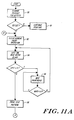
- FIG. 11A a flow chart of the steps comprising the rehydrating scrub cycle of the present invention is illustrated.
- the operator of ink-jet printer 10 visually checks the printer output for defects in the printing quality of the printheads, as indicated by step 90 of FIG. 11A. If no print errors exist, normal operation of printer 10 continues, as indicated by step 91. If the print quality degrades below an acceptable level, or if a visually detectable defect exists, the operator stops the current print operation, as indicated by step 92. The stepping of the current operation or clearing of the printhead typically occurs by depressing a clear button on control panel 28 of printer 10.
- Such control operations provided by presently available microprocessors, are well-known in the prior art and form no part of this invention.
- the initial phase of the rehydrating scrub cycle begins with printhead 31 moving across the distal tip of blade 61 at a slow rate, preferably 1 inch per second, after blade 61 has been indexed into a vertical position, as previously described.
- a slow rate preferably 1 inch per second
- the printhead spits ink onto blade 61, as indicated by step 94 of FIG. 11A, referred to as a "wetting" pass.
- the ink ejected from printerhead 31 moistens the distal tip of blade 61 and further moistens any dried ink and encrusted contaminants on nozzle plate 37. Some wiping occurs in this wetting pass.
- printhead 31 is again drawn across blade 61 at a slow speed, preferably 1 inch per second, referred to as a "wiping" pass, indicated by step 96 of FIG. 11A.
- the wiping pass further loosens and removes any contaminants and rehydrated ink.
- the rehydrating scrub cycle of the present invention provides four wetting passes each followed by four wiping passes to ensure that nozzle plate 37 is free of contaminants
- the wiping passes must occur before the ink ejected in the wetting passes begins to dry on the nozzle plate of the printhead and the wiper blade.
- the number and sequence of wetting and wiping passes may be selected according to the ink used and the printing environment. More passes may be required for more viscous ink, for finer solid contaminants or for faster build up of contaminants. It will be further obvious to those reasonably skilled in the art how to program microprocessor 29 to achieve the desired type, number, sequence, of passes of the printhead 31 over blade 61.
- the above-described initial phase of the rehydrating scrub cycle is generally effective in removing encrusted contaminants from nozzle plate 37.
- inadvertent mixing of colored ink on the nozzle plate 37 may occur.
- second and third phases of the rehydrating scrub cycle are executed.
- printer 10 executes a test pattern in which each nozzle of nozzle plate 37 prints a horizontal line to determine whether each nozzle is firing properly and to clear any mixing of ink which may have occured on nozzle plate 37.
- a dense pattern of graphics in the form of bar graphs is printed to ensure that all nozzles for each color of printhead 31 are firing properly and to clear any mixing of ink which may have occurred on nozzle plate 37.
- another print test pattern of horizontal lines for each nozzle is printed. This printing step of test patterns is indicated as step 98 of FIG. 11A. The printer operator visually inspects the printed test patterns to determine whether a problem exists with any particular nozzle or set of nozzles of printhead 31.
- a sequence of ink spitting and wiping passes is performed. As indicated by step 100 of FIG. 11B, printhead 31 spits ink ten times into spittoon 41. Next, four wiping passes are executed in which the printhead is drawn across the tip of blade 61 at a higher speed, preferably 6 inches per second. The combined sequence of 10 spits followed by four wiping passes is executed four times to further ensure removal of excess ink from nozzle plate 37 and allow the nozzles to spit out encrusted material which has been loosened during the previous phases of the rehydrating scrub cycle.
- the operator of printer 10 examines the print quality for further defects, as indicated by step 104 of FIG. 11B. If the defects have been removed, normal printing operation continues, as indicated by step 105. If defects in print quality continue to exist, the rehydrating scrub cycle may be executed as many as three times. If a printing defect still exists, replacement of the printhead cartridge may be necessary, as indicated by step 106 of FIG. 11B.
- the rehydrating scrub cycle described above may be utilized with black printhead 33 in a manner similar to that utilized for freeing printhead 31 of contaminants. Because there is no danger of ink mixing on black printhead 33, fewer wiping and wetting passes may be required than the above described method. However, the steps of the rehydrating scrub cycle are substantially similar.
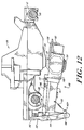
- a second embodiment of the present invention referred to generally as wiper mechanism 140, will now be described with particular reference to FIGS. 12-20.
- This second embodiment is particularly desirable in printers which require a high air-flow environment, as more vigorous scrubbing can be produced to remove dried ink and ink can be spit onto the blades to rehydrate the ink for each wiping operation.
- a typical ink-jet printer 110 with which the wiper of the second embodiment of the present invention may be used is substantially similar to printer 10 of the first embodiment of the present invention, except that printhead carriage 114 travels back and forth through the printing zone on carriage rods 118 and 119. Accordingly, the configuration of printhead carriage 114 has been modified to receive the second carriage rod 119. Referring to FIG.
- printhead carriage 114 a side view of printhead carriage 114 is shown illustrating its relationship to wiper mechanism 140.
- Printhead carriage 114 is slidably mounted on carriage rods 118 and 119 which are received by carriage rod recepticles 120 and 121, respectively. Two carriage rods are preferred for greater accuracy in positioning the printhead carriage.
- Printhead carriage 114 includes print cartridges 130 and 132.
- Print cartridge 130 includes color printhead 131 with nozzle plate 137 which are similar in function and design to printhead 31 and its nozzle plate 37 of printer 10 of the first embodiment.
- print cartridge 130 includes black printhead 133, which is similar in function and design to black printhead 33 of printer 10 of the first embodiment.
- printheads 131 and 133 preferably are positioned at the same level on printhead carriage 114 and therefore have the same printhead to paper spacing. Otherwise, the means by which the printhead carriage 114 is positioned and the operation of the printheads 131 and 133 are similar to that of printer 10 of the first embodiment.
- a cam 180 is secured to the rear of printhead carriage 114 to selectively engage wiper mechanism 140, depending on the position of printhead carriage 114, as explained hereinafter.
- wiper mechanism 140 is comprised of wiper frame 150, first cam follower 142, second cam follower 144, lever 146, slider mechanism 148, axle 152, color blade 154, black blade 156, blade cleaners 158 and 160, blade cleaner supports 162 and 164, spring 166, bosses 168, and disks 170.
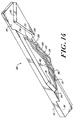
- wiper frame 150 is generally rectangular in shape with a frame arm 151 extending perpendicularly from one side thereof. Wiper frame 150 is pivotally coupled to the machine frame in the service station at pivot point 172 to permit pivoting about axis 155.
- the distal end of frame arm 151 includes a pair of spaced downwardly facing legs 151D.
- a first cam follower 142 is disposed intermediate legs 151D and pivotally coupled at its proximal end 142P to the lower ends of the legs 151D.
- a distal tip 142D is disposed at the opposite end of cam follower 142. The extreme distal portion of tip 142D has a tapered shape to facilitate engaging cam 180, as explained hereinafter.
- the proximal end 142P of cam follower 142 has a tab tip which extends toward wiper frame 150, as illustrated in FIG. 13.
- the tab on proximal end 142P of cam follower 142 is coupled to arm 151 of wiper frame 150 by a coil spring 166 which biases first cam follower 142 in a direction away from wiper frame 150.
- a U-shaped stop 170 is attached to legs 151D of arm 151 to limit pivoting of cam follower 142 away from arm 151.
- a downward force, applied to distal tip 142D of cam follower 142 will cause wiper frame 150 to pivot about axis 155 at pivot point 172, as explained hereinafter.
- a second cam follower 144 includes a generally U-shaped body portion with upwardly facing arms 144A and 144B, as illustrated in FIG. 13.
- a pair of bosses 168 project perpendicularly from the sides of cam follower 144 near its base. Bosses 168 enable cam follower 144 to be pivotally mounted to the machine frame in the service station of printer 110.
- Arm 144A of cam follower 144 includes a distal tip 144D which has a configuration of lateral surfaces adapted to interact with cam 180 of printhead carriage 114, as explained hereinafter.
- Arm 144B of cam follower 144 has a pair of spaced legs.
- a lever 146 is disposed between the legs and is pivotally coupled thereto.
- the second end of lever 146 is pivotally coupled to a slider mechanism 148 which is in turn slidably mounted about one side of wiper frame 150 in a sleeve-like manner.
- Slider 148 is coupled to a conventional ratchet mechanism 149 which converts the reciprocating motion of slider 148 into a rotary motion for rotation of the wiper blades, as explained hereinafter.
- An axle 152 having a pair of octagonal-shaped disks at each end thereof, is rotatably mounted at each end in wiper frame 150.
- a wiper blade 154 is disposed intermediate octagonal disks 172 at one end of axle 152
- an octagonal-shaped wiper blade 156 is disposed intermediate octagonal disks 174 at the opposite end of axle 152.
- Disks 174 should have the same configuration as blades 154 and 156.
- a series of flat edges should be provided on each blade 154 and 156.
- Blades 154 and 156 have a polygonal shape and may be square, or hexagonal or some other configuration. However, the preferred configuration is octagonal.
- Wiper blades 154 and 156 are preferably formed of a resilient material such as nitrile rubber or the like so that as a printhead passes over the wiper blade, the blade flexes to accommodate the irregular surface of the printhead and then returns to its original configuration without substantial deformation.
- the exterior disk 174 adjacent wiper 154 is coupled to ratchet mechanism 149 so that axle 152 and blades 154 and 156 will rotate in a clockwise direction when slider 148 activates ratchet mechanism 149 in a conventional manner which is well understood by those skilled in the art.
- a pair of blade cleaners, 158 and 160 preferably each comprised of an absorbent material, and having a slit in one side thereof is mounted to wiper frame 150 by support members 162 and 164, respectively.
- Blade wipers 158 and 160 are positioned to receive the perimeter of blades 154 and 156 respectively within their slits in tight frictional engagements to wipe the edges of their respective blades. As wiper blades 154 and 156 are indexed, they pass through the slit in blade cleaners 158 and 160, respectively, and the top and sides of the most recently used blade edges are freed of ink, dust, lint and any other contaminants which may be adhered thereto.
- wipers 158 and 160 help to retain blades 154 and 156 in their indexed position to prevent movement thereof during wiping, as will be described hereinafter.
- Wipers 158 and 160 are preferably comprised of a contaminant-free, ink-absorbing material which wicks the ink away from the blades.
- An acceptable, commercially available material is sold under the trade name Texwipe, by Texwipe Corporation.
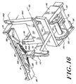
- the wiper mechanism 140 of the second embodiment of the present invention when pivotally mounted to the service station of printer 110, provides contact between wiper blades 154 and 156 and printheads 131 and 132 respectively, depending upon the position of printhead carriage 114 in relation to wiper mechanism 140. Blade 154 only wipes printhead 131 and blade 156 only wipes printhead 132 to prevent cross-contamination.
- Cam 180 attached to printhead carriage 114, has a plurality of camming surfaces separated by dividing walls.
- first cam follower 142 engages cam 180.
- the distal tip 142D of cam follower 142 rides up on the camming surfaces of cam 180 which pushes follower 142 downwardly and causes a pivoting of wiper frame 150 about axis 155.
- a corresponding but opposite upward displacement of wiper blades 154 and 156 is produced.
- wiper blades 154 and 156 may be selectively deflected upward to contact printheads 131 and 133, respectively, as printhead carriage 114 passes over wiper mechanism 140.
- wiper blades 154 and 156 will be brought into selective contact with printheads 131 and 133, respectively, to allow for wiping thereof.
- the wiper blades remain stationary while the nozzle plate of the printhead is drawn back and forth across the wiper blade in an oscillating manner. Unlike the first embodiment, however, both the color printhead 131 and the black printhead 133 are wiped simultaneously.
- cam 180 engages second cam follower 144 causing an indexing of wiper blades 154 and 154.
- the indexing of wiper blades 154 and 156 occurs as follows.
- cam 180 disengages first cam follower 142 and engages second cam follower 144.
- Cam 180 selectively deflects distal tip 144D of second cam follower 144. The deflection of distal tip 144D causes pivotal rotation of cam follower 144 about axis 165.
- the rotary motion of cam follower 144 is translated into a reciprocating motion by lever 146 which is pivotally coupled to both cam follower 144 and slider 148.
- Slider 148 imparts the reciprocating motion to ratchet mechanism 149 which in turn rotates axle 152 and wiper blades 154 and 156 so that the next available edge of each octagonal blade is facing upwardly.
- wiper blades 154 and 156 rotate, the blade used in the most recent wiping of the printheads is drawn through the slit in blade cleaners 158 and 160 respectively causing a cleaning thereof.
- Cam 180 has a flat, rectangular top surface from which a number of camming surfaces, ramps and grooves project downwardly.
- Cam 180 comprises top surface 181, cam surfaces 182, 184 and 186, cam grooves 188, 190, and 198, ramps 191-197, walls 200, 202 and 204, and release surfaces 206, 208 and 210.
- cam surfaces 182, 184, and 186 and cam groove 198 lie in planes parallel to top surface 181.
- Ramps 192 and 193 extend perpendicularly from cam surface 186.
- Ramps 194, 195, 196 and 197 extend perpendicularly from cam groove 198.
- Walls 200, 202, and 204 extend perpendicularly from cam surface 182.
- Cam groove 188 lies intermediate walls 200 and 202.
- Cam groove 190 lies intermediate wall 202 and 204.
- the surfaces which comprise cam grooves 188 and 190 lie in planes which are parallel to the top surfaces their adjacent walls.
- Ramp 191 extends between cam surfaces 182 and 184 and lies adjacent wall 204.
- Wall 200 is terminated at one end by an oblique surface, designated release surface 206.
- walls 202 and 204 are terminated by oblique surfaces, designated release surfaces 208 and 210, respectively.
- Cam 180 is preferably comprised of a rigid material such as plastic or the like so that the cam will not deform when engaged by cam followers 142 and 144, causing unintended displacements or deflections thereof as cam 180 moves over the cam followers.
- FIGS. 16-20 A description of the engagement of wiper 140 and cam 180 to facilitate wiping of printheads 131 and 133 will be described with reference to FIGS. 16-20. All directions, such as right and left are provided with reference to Figs. 16-20.
- cam 180 engages first cam follower 142.
- the path of cam 180 across distal tip 142D of cam follower 142 is illustrated by dashed line 250 in FIG. 17.
- cam surface 182 moves over distal tip 142D.
- distal tip 142D reaches the edge of cam surface 184 and pivots upward to its normal position causing a corresponding downward movement of wiper blades of 154 and 156 away from printheads 131 and 133, respectively.
- Printhead carriage 114 then changes direction, now moving leftwardly.
- tip 142D which is spring biased away from wiper 140, contacts ramp 192 and is deflected thereby.
- Tip 142D is increasingly deflected as it follows ramp 192.
- tip 142D follow ramp 193 which maintain its deflection, as cam 180 continues leftward.
- tip 142D pivots, because of its spring bias, into cam groove 188.
- printhead carriage 114 again reverses direction now moving rightwardly.
- distal tip 142D retained by walls 200 and 202, contacts cam groove 188 which causes a gradual downward displacement of tip 142D and a corresponding gradual, upward displacement of blades 154 and 156.
- surface 188A at the center of cam groove 188 reaches tip 142D, the displacement of tip 142D and blades 154 and 156 remains constant.
- blades 154 and 156 are in contact with nozzle plates 137 and 139, respectively as shown in FIG. 18.
- nozzle plates 137 and 139 are drawn across blades 154 and 156, respectively.
- the ink previously deposited on the blades helps to rehydrate dried ink on the nozzle plates and loosen encrusted contaminants as the nozzle plates are drawn across the blade tips.
- the resulting wiping action is referred to as a "short" or “scrub” stroke.
- Each "scrub" stroke should occur before the ink previously ejected begins to dry on the nozzle plates and the wiper blades.
- tip 142D is gradually displaced upwardly, causing blades 154 and 156 to be gradually displaced downwardly.
- printhead carriage 114 and cam 180 changes directions, moving leftwardly so that cam groove 188 displaces tip 142D downwardly a second time causing a second short scrub stroke of the printheads.
- cam 180 is moving leftwardly with distal tip 142D biased against wall 202.
- tip 142D because of its spring bias, pivots into cam groove 190, as indicated in FIG. 17.
- printhead carriage 114 again changes direction, now moving rightwardly.
- cam groove 190 is drawn across distal tip 142D causing a gradual, downward, displacement thereof and a corresponding gradual, upward displacement of blades 154 and 156.
- surface 198A at the center of cam groove 190, is drawn across distal tip 142D, cam follower 142 reaches a constant vertical displacement.
- blades 154 and 156 are in contact with nozzle plates 137 and 139, respectively.
- nozzle plates 137 and 139 are drawn across blades 154 and 156, respectively, as long as distal tip 142D is in contact with cam surface 190A.
- surface 190A is considerably larger than surface 188A allowing for greater contact between the wiper blades and the nozzle plates.
- the resulting wiping action is referred to as a "wiping" stroke.
- the cam groove 190 is drawn across distal tip 142D at a rate of approximately twelve inches per second, causing nozzle plates 137 and 139 to be drawn across wiper blades 154 and 156, respectively, at the same rate. It should be understood that the speed with which printhead carriage 114 and cam 180 are drawn across wiper mechanism 140 may vary according to the environment and the viscosity of the ink used in ink jet printer 110. The above rate used in the preferred embodiment should not be interpreted as limiting in any manner.
- distal tip 142D reaches the edge of cam groove 190 and is displaced upwardly therefrom. Tip 142D is biased against ramp 192 which it follows until reaching its neutral position. As printhead carriage 114 and cam 180 continue rightwardly, surface 186 moves above distal tip 142D without contact.
- second cam follower 144 of wiper mechanism 140 engages cam 180.
- cam 180 moves farther rightwardly, second cam follower 144 is received within cam groove 198 which moves above distal tip 144D in a noncontacting manner.
- cam 180 continues rightwardly distal tip 144D contacts ramp 194 and is increasingly deflected thereby, following the path indicated by dashed line 260 of FIG. 19.
- the deflection of distal tip 144D causes pivotal rotation of cam follower 144 about axis 165.
- the rotary motion of cam follower 144 is translated into a reciprocating motion by lever 146 which is pivotally coupled to both cam follower 144 and slider 148.
- Slider 148 imparts the reciprocating motion to ratchet mechanism 149 which in turn rotates axle 152 and wiper blades 154 and 156 so that the next available edge of each octagonal blade is facing upwardly.
- wiper blades 154 and 156 rotate, the blade edges used in the most recent wiping of the printheads are drawn through the slits blade cleaners 158 and 160, respectively, causing a cleaning thereof.
- printhead carriage 114 continues rightwardly distal tip 144D contacts ramp 197 and remains in a deflected position, as indicated in FIG. 19 as printhead carriage 114 comes to rest in the service station area. Printhead carriage 114 is then in a position, as previously described with regard to the first embodiment of the present invention, in which printheads 131 and 133 are capped. When a print request is received, printhead carriage 114 leaves the service area moving leftwardly, causing distal tip 144D of second cam follower 144 to disengage from cam 180, following the same path as that of its initial engagement except in reverse, as indicated in FIG. 19.
- cam 180 re-engages distal tip 142D of first cam follower 142, as shown by dashed line 270 in FIG. 20.
- Cam surface 186 moves above distal tip 142 in a noncontacting manner.
- tip 142D is deflected by ramp 192.
- Tip 142D is deflected by ramp 192 which it follows until reaching ramp 193.
- tip 142D follows ramp 193 until reaching release point 206.
- tip 142D pivots against wall 202 which it follows briefly until reaching release point 208.
- tip 142D pivots against wall 204 which it follows briefly until reaching release point 210.
- tip 142D is biased to its normal position.
- surface 182 and cam groove 198 move over distal tip 142D, without further contact as printhead carriage 114 moves into the print zone, as indicated in FIG. 20.
- the contact between cam 180 and the cam followers does not cause further pivoting of wiper frame 150 or rotation of blades 154 and 156, and no wiping or blade rotation occurs.
- the wiping of printheads 131 and 133 may occur at the end of every page. It may be appreciated, however, that the wiping sequence may occur at more frequent intervals as desired.
- printhead carriage 114 is oscillated in a back and forth manner to provide four short "scrub" strokes followed by one long "wipe” stroke, and further followed by a rotation of wiper blades 154 and 156 prior to capping of printheads 131 and 133. It will be obvious to those reasonably skilled in the art that the position of printhead carriage 114 may be manipulated to achieve other sequences or types of wiping action, the instructional algorithms used to manipulate the printhead carriage 114 for such actions being obvious to those reasonably skilled in the art.
- cam 180 may be modified to achieve different deflections and displacements of cam followers 144 and 142 to achieve different pivoting and rotation of wiper blades 154 and 156. Also, the points at which ink is spit on to the blades can be adjusted or eliminated entirely, depending upon the requirements of the particular printer with which this invention is used.
- the wiper of this invention permits the removal of dust, ink and other contaminants from color and black printheads, and prevents their buildup during use. Cross contamination of the printheads is prevented, and automatic self-cleaning is provided.
Landscapes
- Ink Jet (AREA)
Claims (21)
- Dispositif pour nettoyer une première et une deuxième têtes d'impression disposées sur un chariot (14) de têtes d'impression dans une imprimante à jet d'encre, comprenant :
une première lame d'essuyage (61, 154) destinée à essuyer une première tête d'impression (31) ;
une deuxième lame d'essuyage (63, 158) destinée à essuyer une deuxième tête d'impression (33) ;
des moyens (65) actionnés en réponse au mouvement du chariot porte-tête d'impression, servant à mettre sélectivement ladite première lame d'essuyage (61) en contact d'essuyage exclusivement avec ladite première tête d'impression (31) et à mettre sélectivement ladite deuxième lame d'essuyage (63) en contact d'essuyage exclusivement avec la deuxième tête d'impression (63) ; et
des moyens (14, 27, 29, 19, 18) servant à produire un mouvement relatif d'essuyage entre ladite première tête d'impression (31) et ladite première lame d'essuyage (61) et entre ladite deuxième tête d'impression (33) et ladite deuxième lame d'essuyage (63). - Dispositif selon la revendication 1, dans lequel le chariot porte-tête d'impression (14) se déplace dans les deux sens à travers une zone d'impression dans laquelle une impression est produite par les première et deuxième têtes d'impression (31, 33) sur un milieu d'impression, et dans lequel lesdites premières et deuxièmes lames d'essuyage (61, 63) sont disposées dans une zone (36) de station d'entretien disposée à l'extérieur de ladite zone d'impression, dans le voisinage d'une extrémité de la zone d'impression.
- Dispositif selon la revendication 2, dans lequel lesdits moyens de positionnement (65) sont actionnés par le mouvement d'introduction du chariot porte-têtes d'impression (14) dans la zone de station d'entretien (36).
- Dispositif selon la revendication 3, dans lequel des surfaces (54, 55) du chariot porte-têtes d'impression (14) interagissent mécaniquement avec au moins un bras (66) associé auxdits moyens de positionnement (65) pour amener lesdits moyens de positionnement (65) à positionner sélectivement ladite première lame d'essuyage (61) en contact d'essuyage exclusivement avec ladite première tête d'impression (31) et à positionner sélectivement ladite deuxième lame d'essuyage (63) en contact d'essuyage exclusivement avec ladite deuxième tête d'impression (33).
- Dispositif selon la revendication 4, dans lequel lesdits moyens de production (14, 18, 19, 27, 29) comprennent des moyens (19, 27, 29) servant à mettre le chariot porte-têtes d'impression (14) en mouvement.
- Dispositif selon la revendication 5, dans lequel lesdits moyens de mise en mouvement comprennent :
un moteur (27) ;
des moyens (19) qui accouplent ledit moteur au chariot porte-têtes d'impression ;
des moyens du type ordinateur (29) servant à commander ledit moteur (27) et lesdits moyens d'accouplement (19) ; et
des moyens (18) servant à guider le mouvement du chariot porte-têtes d'impression (14) dans ladite zone de station d'entretien (36). - Dispositif selon la revendication 1, comprenant en outre des moyens (64) servant à éliminer les souillures desdites première et deuxième lames d'essuyage (61, 63).
- Dispositif selon la revendication 7, dans lequel lesdits moyens d'élimination comprennent au moins une racle (72).
- Dispositif selon la revendication 1, dans lequel ladite première lame d'essuyage (61) et ladite deuxième lame d'essuyage (63) font saillie sur un corps d'essuyage (60) qui peut tourner autour d'un axe central.
- Dispositif selon la revendication 9, dans lequel lesdites première et deuxième lames d'essuyage (61, 63) s'étendent sensiblement radialement vers l'extérieur à partir dudit axe central et ont des pointes distales qui sont espacées l'une de l'autre.
- Dispositif selon la revendication 9 ou 10, dans lequel lesdits moyens de positionnement (65) comprennent des moyens (62, 66, 67, 68, 69) servant à faire tourner ledit corps d'essuyage (60) autour dudit axe (60) autour dudit axe de rotation central.
- Dispositif selon la revendication 11, dans lequel lesdits moyens de rotation (62, 66, 67, 68, 69) répondent au mouvement du chariot porte-têtes d'impression (14).
- Dispositif selon la revendication 12, dans lequel lesdits moyens de rotation (62, 66, 67, 68, 69) comprennent un bras de levier (66) actionné par le mouvement du chariot porte-têtes d'impression (14).
- Dispositif selon la revendication 13, dans lequel ledit bras de levier (66) est sélectivement actionné par le mouvement du chariot porte-têtes d'impression (14) dans un seul sens.
- Dispositif selon la revendication 10, dans lequel ladite première lame d'essuyage (61) et ladite deuxième lame d'essuyage (63) ont chacune une longueur qui s'étend de ladite pointe distale audit axe de rotation, dans lequel la longueur de ladite première lame d'essuyage (61) diffère de la longueur de ladite lame d'essuyage, et dans lequel ladite première tête d'impression (31) a un écartement tête d'impression-papier différent de l'écartement tête d'impression-papier de la deuxième tête d'impression (33).
- Dispositif selon la revendication 1, comprenant en outre une troisième lame d'essuyage (61A) servant à nettoyer la première tête d'impression (31) et une quatrième lame d'essuyage (63A) servant à nettoyer la deuxième tête d'impression (33).
- Dispositif selon la revendication 1, dans lequel lesdites première (154) et deuxième (156) lame d'essuyage ont chacune une forme polygonale et un axe de rotation central passant par le centre de ces lames.
- Dispositif selon la revendication 17, dans lequel lesdits moyens de positionnement comprennent :
une came (180) accouplée au chariot porte-têtes d'impression ;
un cadre (150) monté pivotant, auquel lesdites première et deuxième lames (154, 156) sont fixées ; et
une contre-came (142) qui répond au mouvement de ladite came (180) en faisant pivoter ledit châssis (150) autour d'un axe de rotation. - Dispositif selon la revendication 18, dans lequel lesdites première et deuxième lames d'essuyage (154, 156) sont sélectivement basculées en contact avec ladite première tête d'impression (131) et avec ladite deuxième tête d'impression (133) respectivement en réponse à ladite came (180).
- Dispositif selon la revendication 18, comprenant en outre des moyens d'indexage (144, 146, 148, 152, 174) servant à faire tourner lesdites première et deuxième lame d'essuyage (154, 156) autour dudit axe de rotation central.
- Dispositif selon la revendication 20, comprenant des premier (162) et deuxième (164) organes absorbeurs disposés en contact de frottement avec lesdites premières (154) et deuxièmes (156) lames d'essuyage respectivement pour absorber les souillures pendant que lesdites lames d'essuyage sont mises en rotation.
Applications Claiming Priority (2)
| Application Number | Priority Date | Filing Date | Title |
|---|---|---|---|
| US549583 | 1990-07-05 | ||
| US07/549,583 US5103244A (en) | 1990-07-05 | 1990-07-05 | Method and apparatus for cleaning ink-jet printheads |
Publications (3)
| Publication Number | Publication Date |
|---|---|
| EP0465260A2 EP0465260A2 (fr) | 1992-01-08 |
| EP0465260A3 EP0465260A3 (en) | 1992-02-26 |
| EP0465260B1 true EP0465260B1 (fr) | 1995-10-04 |
Family
ID=24193588
Family Applications (1)
| Application Number | Title | Priority Date | Filing Date |
|---|---|---|---|
| EP91306107A Expired - Lifetime EP0465260B1 (fr) | 1990-07-05 | 1991-07-04 | Méthode et appareil de nettoyage d'une plaque à orifice de gicleurs d'encre |
Country Status (4)
| Country | Link |
|---|---|
| US (1) | US5103244A (fr) |
| EP (1) | EP0465260B1 (fr) |
| JP (1) | JP3290448B2 (fr) |
| DE (1) | DE69113534T2 (fr) |
Cited By (1)
| Publication number | Priority date | Publication date | Assignee | Title |
|---|---|---|---|---|
| US7118189B2 (en) | 2004-05-28 | 2006-10-10 | Videojet Technologies Inc. | Autopurge printing system |
Families Citing this family (152)
| Publication number | Priority date | Publication date | Assignee | Title |
|---|---|---|---|---|
| EP0494693B1 (fr) | 1991-01-11 | 1998-04-01 | Canon Kabushiki Kaisha | Appareil d'enregistrement par jet d'encre |
| JP2901361B2 (ja) * | 1991-02-28 | 1999-06-07 | キヤノン株式会社 | インクジェット記録装置 |
| EP0513833B1 (fr) * | 1991-05-15 | 1996-09-25 | Seiko Epson Corporation | Dispositif d'enregistrement du type à jet d'encre et procédé de nettoyage de la tête d'enregistrement |
| JP3058200B2 (ja) * | 1991-06-24 | 2000-07-04 | セイコーエプソン株式会社 | インクジェット記録装置 |
| US5155497A (en) * | 1991-07-30 | 1992-10-13 | Hewlett-Packard Company | Service station for ink-jet printer |
| DE69325532T2 (de) * | 1992-03-09 | 1999-12-02 | Canon K.K., Tokio/Tokyo | Mehrfachaufzeichnungsvorrichtung mittels eines Monochromdruckers |
| JP3110151B2 (ja) * | 1992-04-14 | 2000-11-20 | キヤノン株式会社 | インクジェット記録装置 |
| JP2832776B2 (ja) * | 1992-06-12 | 1998-12-09 | キヤノン株式会社 | インクジェット記録装置 |
| EP0581553B1 (fr) * | 1992-07-28 | 1998-10-28 | Canon Kabushiki Kaisha | Mécanisme de nettoyage pour une tête d'enregistrement à jet d'encre et appareil d'enregistrement l'utilisant |
| US5434605A (en) * | 1992-09-21 | 1995-07-18 | Hewlett-Packard Company | Automatic failure recovery method and system for ink-jet printheads |
| US5644347A (en) * | 1992-09-21 | 1997-07-01 | Hewlett-Packard Company | Inkjet printer with variable wiping capabilities for multiple printheads |
| US5563638A (en) * | 1992-09-21 | 1996-10-08 | Hewlett-Packard Company | Ink-jet printhead capping and wiping method and apparatus |
| US5621441A (en) * | 1992-09-21 | 1997-04-15 | Hewlett-Packard Company | Service station for inkjet printer having reduced noise, increased ease of assembly and variable wiping capability |
| US5396277A (en) * | 1992-09-25 | 1995-03-07 | Hewlett-Packard Company | Synchronized carriage and wiper motion method and apparatus for ink-jet printers |
| EP0590853B1 (fr) * | 1992-09-30 | 2000-11-08 | Hewlett-Packard Company | Méthode et système de sélection de palettes de couleurs pour imprimante à jet d'encre |
| JP3535885B2 (ja) * | 1992-12-16 | 2004-06-07 | セイコーエプソン株式会社 | インクジェット式記録装置 |
| US5440331A (en) * | 1992-12-21 | 1995-08-08 | Hewlett-Packard Company | Printhead servicing apparatus |
| US5394178A (en) * | 1992-12-21 | 1995-02-28 | Hewlett-Packard Company | Printhead servicing apparatus with pivotal servicing lever |
| DE69310488T2 (de) * | 1992-12-28 | 1997-12-04 | Canon Kk | Tintenstrahlaufzeichnungsgerät und Rückgewinnungsverfahren dafür |
| JP3241844B2 (ja) * | 1993-01-25 | 2001-12-25 | キヤノン株式会社 | 記録装置及び記録方法 |
| JPH06340081A (ja) * | 1993-04-19 | 1994-12-13 | Xerox Corp | 全幅インクジェットプリンタ用プリントヘッドメンテナンス装置 |
| US5585826A (en) * | 1993-04-30 | 1996-12-17 | Hewlett-Packard Company | Service station for simultaneous capping/wiping of multiple inkjet cartridges having different inks |
| US5455608A (en) * | 1993-04-30 | 1995-10-03 | Hewlett-Packard Company | Pen start up algorithm for black and color thermal ink-jet pens |
| US5602573A (en) * | 1993-04-30 | 1997-02-11 | Hewlett-Packard Company | Service station for inkjet printer having wipers with concave wiping edges |
| JP3262410B2 (ja) * | 1993-06-21 | 2002-03-04 | キヤノン株式会社 | インクジェット記録装置 |
| US5424768A (en) * | 1993-06-21 | 1995-06-13 | Xerox Corporation | Zero-volume maintenance cap for an ink jet printhead |
| US5500660A (en) * | 1993-06-24 | 1996-03-19 | Hewlett-Packard Company | Wiper for inkjet printhead nozzle member |
| US5534897A (en) * | 1993-07-01 | 1996-07-09 | Xerox Corporation | Ink jet maintenance subsystem |
| US5489927A (en) * | 1993-08-30 | 1996-02-06 | Hewlett-Packard Company | Wiper for ink jet printers |
| US6206497B1 (en) * | 1993-09-10 | 2001-03-27 | Canon Kabushiki Kaisha | Liquid ejecting apparatus with variable wiping of a liquid ejection head |
| US5612722A (en) * | 1993-10-26 | 1997-03-18 | Lexmark International, Inc. | Ink jet printhead wiper having side surfaces intersecting a top surface at acute angles to form wiping edges and a slat centered in a bottom surface |
| US5563637A (en) * | 1993-10-26 | 1996-10-08 | Lexmark International, Inc. | Maintenance station for ink jet printhead |
| IT1261111B (it) * | 1993-11-11 | 1996-05-09 | Olivetti Canon Ind Spa | Stazione di pulizia per una stampante a getto di inchiostro |
| JPH07137270A (ja) * | 1993-11-16 | 1995-05-30 | Canon Inc | インクジェット記録装置 |
| DE4443923B4 (de) * | 1993-12-10 | 2008-08-07 | Seiko Epson Corp. | Tintenstrahldrucker |
| JP3088615B2 (ja) * | 1994-01-25 | 2000-09-18 | キヤノン株式会社 | 排インク処理方法及びそれを実施する回復装置とインク吐出装置 |
| JPH07246708A (ja) * | 1994-03-10 | 1995-09-26 | Canon Inc | インクジェット記録装置 |
| US5572245A (en) * | 1994-03-10 | 1996-11-05 | Hewlett-Packard Company | Protective cover apparatus for an ink-jet pen |
| US5712668A (en) * | 1994-03-25 | 1998-01-27 | Hewlett-Packard Company | Rotary Multi-ridge capping system for inkjet printheads |
| US5617124A (en) * | 1994-03-25 | 1997-04-01 | Hewlett-Packard Company | Self-cleaning service station for inkjet printing mechanisms |
| US5614930A (en) * | 1994-03-25 | 1997-03-25 | Hewlett-Packard Company | Orthogonal rotary wiping system for inkjet printheads |
| US6000780A (en) * | 1994-04-08 | 1999-12-14 | Hewlett-Packard Company | Wiping system for inkjet printer |
| US5644346A (en) * | 1994-04-08 | 1997-07-01 | Hewlett-Packard Company | Modular wiping unit for inkjet printer |
| EP0676289B1 (fr) * | 1994-04-08 | 1999-02-10 | Hewlett-Packard Company | Technique de nettoyage humide pour tête d'impression à jet d'encre |
| JPH07290724A (ja) * | 1994-04-21 | 1995-11-07 | Fujitsu Ltd | インクジェットヘッドのクリーニング方法及びその装置 |
| EP0714778B1 (fr) * | 1994-05-17 | 2000-03-22 | Seiko Epson Corporation | Enregistreur a jet d'encre et procede de nettoyage de la tete d'enregistrement |
| US5563639A (en) * | 1994-09-30 | 1996-10-08 | Hewlett-Packard Company | Venturi spittoon system to control inkjet aerosol |
| EP0705700B1 (fr) * | 1994-09-30 | 1998-05-20 | Hewlett-Packard Company | Cheminées multiples pour imprimante à jet d'encre |
| US5627572A (en) * | 1994-10-24 | 1997-05-06 | Lexmark International, Inc. | Programmable head type detection and maintenance system |
| US5694157A (en) * | 1994-10-28 | 1997-12-02 | Hewlett-Packard Company | Multiple wiper servicing system for inkjet printheads |
| US5706038A (en) * | 1994-10-28 | 1998-01-06 | Hewlett-Packard Company | Wet wiping system for inkjet printheads |
| US5592202A (en) * | 1994-11-10 | 1997-01-07 | Laser Master Corporation | Ink jet print head rail assembly |
| US5589865A (en) * | 1994-12-14 | 1996-12-31 | Hewlett-Packard Company | Inkjet page-wide-array printhead cleaning method and apparatus |
| US5635965A (en) * | 1995-01-31 | 1997-06-03 | Hewlett-Packard Company | Wet capping system for inkjet printheads |
| US5583548A (en) * | 1995-03-01 | 1996-12-10 | Hewlett-Packard Company | Bi-directional wiper for ink jet printhead and method of operation |
| US5714991A (en) * | 1995-03-03 | 1998-02-03 | Hewlett-Packard Company | Rotary priming system for inkjet printheads |
| US5898445A (en) * | 1995-03-06 | 1999-04-27 | Hewlett-Packard Company | Translational wiping technique for a stationary inkjet printhead |
| US5984450A (en) * | 1995-03-06 | 1999-11-16 | Hewlett-Packard Company | Inkjet printer having multiple printheads and multiple independent printhead service stations for performing different wiping procedures |
| US5886714A (en) * | 1995-03-06 | 1999-03-23 | Hewlett-Packard Company | Actuation mechanism for translational wiping of a stationary inkjet printhead |
| US5801725A (en) * | 1995-05-03 | 1998-09-01 | Encad, Inc. | Slidable wiping and capping service station for ink jet printer |
| JPH0957989A (ja) * | 1995-08-29 | 1997-03-04 | Oki Data:Kk | インクジェット記録装置 |
| US5757395A (en) * | 1995-09-25 | 1998-05-26 | Hewlett-Packard Company | Color capable single-cartridge inkjet service station |
| US6193350B1 (en) | 1995-09-29 | 2001-02-27 | Hewlett-Packard Company | Method and apparatus for dynamically aligning a printer printhead |
| US5751305A (en) * | 1995-09-29 | 1998-05-12 | Hewlett-Packard Company | Method and apparatus for dynamically aligning a printer printhead |
| US5815176A (en) * | 1996-01-30 | 1998-09-29 | Hewlett-Packard Company | Multi-finned wiping system for inkjet printheads |
| KR980001283U (ko) * | 1996-06-30 | 1998-03-30 | 잉크젯 프린터의 헤드 캡핑장치 | |
| US6132027A (en) * | 1996-07-30 | 2000-10-17 | Fuji Xerox Co., Ltd. | Ink-jet type image forming apparatus |
| US5790147A (en) * | 1996-08-20 | 1998-08-04 | Laser Cycle, Inc. | Method of cleaning an ink jet head |
| US5956053A (en) * | 1996-10-31 | 1999-09-21 | Hewlett-Packard Company | Dual seal capping system for inkjet printheads |
| US5936647A (en) * | 1996-10-31 | 1999-08-10 | Hewlett-Packard Company | Flexible frame onsert capping of inkjet printheads |
| US5905514A (en) * | 1996-11-13 | 1999-05-18 | Hewlett-Packard Company | Servicing system for an inkjet printhead |
| US5914734A (en) * | 1996-11-13 | 1999-06-22 | Hewlett-Packard Company | Printhead servicing system and method using a moveable wiper between a fluid source and a printhead |
| US5907335A (en) * | 1996-11-13 | 1999-05-25 | Hewlett-Packard Company | Wet wiping printhead cleaning system using a non-contact technique for applying a printhead treatment fluid |
| US5969731A (en) * | 1996-11-13 | 1999-10-19 | Hewlett-Packard Company | Print head servicing system and method employing a solid liquefiable substance |
| US6007318A (en) * | 1996-12-20 | 1999-12-28 | Z Corporation | Method and apparatus for prototyping a three-dimensional object |
| US7037382B2 (en) * | 1996-12-20 | 2006-05-02 | Z Corporation | Three-dimensional printer |
| DE69835249T2 (de) | 1997-02-18 | 2007-07-05 | Canon K.K. | Flüssigkeitsausstossvorrichtung |
| JP3428893B2 (ja) * | 1997-02-19 | 2003-07-22 | キヤノン株式会社 | インクジェット記録装置およびインクジェット記録ヘッドの回復方法 |
| US6000779A (en) * | 1997-08-29 | 1999-12-14 | Hewlett-Packard Company | Triple-cartridge inkjet service station |
| JPH11254707A (ja) * | 1998-03-13 | 1999-09-21 | Canon Inc | インクジェット記録装置及びクリーニングユニット |
| DE69826206T2 (de) * | 1997-10-20 | 2005-10-27 | Canon K.K. | Tintenstrahldrucker mit einer verbesserten Reinigungseinheit |
| US6151044A (en) * | 1997-10-29 | 2000-11-21 | Hewlett-Packard Company | Hide-away wiper cleaner for inkjet printheads |
| EP0913262A1 (fr) * | 1997-10-31 | 1999-05-06 | Hewlett-Packard Company | Système de nettoyage avec balais d'essuyage larges et étroits pour têtes d'impression par jet d'encre |
| US6247783B1 (en) | 1998-01-15 | 2001-06-19 | Hewlett-Packard Company | Storage and spittoon system for waste inkjet ink |
| US6299278B1 (en) * | 1998-02-05 | 2001-10-09 | Canon Kabushiki Kaisha | Head wiping mechanism for ink jet printer |
| US6493937B1 (en) | 1998-03-16 | 2002-12-17 | Hewlett-Packard Company | Method of manufacture for ink-jet hard copy apparatus using a modular approach to ink-jet technology |
| US6082854A (en) | 1998-03-16 | 2000-07-04 | Hewlett-Packard Company | Modular ink-jet hard copy apparatus and methodology |
| US6244685B1 (en) | 1998-05-01 | 2001-06-12 | Canon Kabushiki Kaisha | Head wiping arrangement for ink jet printer |
| EP0976563A1 (fr) | 1998-07-31 | 2000-02-02 | Eastman Kodak Company | Nettoyage par ultrasons sans contact pour cartouches de tête d'impression à jet d'encre |
| US6312117B1 (en) | 1998-09-03 | 2001-11-06 | Hewlett-Packard Company | Ink jet printer pen with extra fluid dispenser |
| US6196656B1 (en) | 1998-10-27 | 2001-03-06 | Eastman Kodak Company | High frequency ultrasonic cleaning of ink jet printhead cartridges |
| DE69938285T2 (de) | 1998-12-15 | 2009-03-12 | Canon K.K. | Tintenstrahldrucker |
| US6267464B1 (en) | 1998-12-28 | 2001-07-31 | Eastman Kodak Company | Self cleaning ink jet printhead cartridges |
| US6135585A (en) | 1999-01-08 | 2000-10-24 | Hewlett-Packard Company | Replaceable capping system for inkjet printheads |
| US6193357B1 (en) | 1999-09-24 | 2001-02-27 | Hewlett-Packard Company | Contoured cross-sectional wiper for cleaning inkjet printheads |
| US6428228B1 (en) * | 1999-12-02 | 2002-08-06 | Hewlett-Packard Company | Removable paper module for an orthogonal inkjet printer |
| US6367904B1 (en) * | 1999-12-23 | 2002-04-09 | Hewlett-Packard Company | Wiper cleaning apparatus and method of using same |
| US6402291B1 (en) | 2000-01-31 | 2002-06-11 | Hewlett-Packard Company | Composite wiper for inkjet printheads |
| GB2389079B (en) * | 2000-01-31 | 2004-07-21 | Hewlett Packard Co | Flipping wiper scraper system for inkjet printheads |
| US6561619B1 (en) | 2000-01-31 | 2003-05-13 | Hewlett-Packard Company | Flipping wiper scraper system for inkjet printheads |
| US6352330B1 (en) * | 2000-03-01 | 2002-03-05 | Eastman Kodak Company | Ink jet plate maker and proofer apparatus and method |
| US6409303B1 (en) * | 2000-03-31 | 2002-06-25 | Hewlett-Packard Company | Two-stage scraper system for inkjet wipers |
| US6554391B1 (en) * | 2000-07-20 | 2003-04-29 | Eastman Kodak Company | Rotating disk cleaning assembly apparatus and method for an ink jet print head with fixed gutter |
| JP3728195B2 (ja) * | 2000-10-04 | 2005-12-21 | キヤノン株式会社 | ヘッド回復装置及びヘッド回復方法並びにインクジェット記録装置 |
| US6648449B2 (en) | 2001-08-01 | 2003-11-18 | Hewlett-Packard Development Company, L.P. | Printhead cleaner cassette with switchable wipers |
| US20040155921A1 (en) * | 2001-09-05 | 2004-08-12 | Simmons Laura Elisabeth | Pen wiping method and system that employs a treadmill belt |
| US6547369B1 (en) | 2001-10-12 | 2003-04-15 | Xerox Corporation | Layered cleaning blade and image forming device arranged with the same |
| US6585351B2 (en) | 2001-10-30 | 2003-07-01 | Hewlett-Packard Development Company, L.P. | Angular wiping system for inkjet printheads |
| US6547365B1 (en) | 2001-10-31 | 2003-04-15 | Hewlett-Packard Company | Printhead end of life detection system |
| EP1310367A1 (fr) * | 2001-11-08 | 2003-05-14 | Agfa-Gevaert | Station de maintenance d'un sytème d'impression à jet d'encre |
| US6755504B2 (en) * | 2002-04-26 | 2004-06-29 | Hewlett-Packard Development Company. Lp. | Independent wiping of printhead |
| US7275534B2 (en) * | 2003-01-31 | 2007-10-02 | Hewlett-Packard Development Company, L.P. | Medicament ejector with ejection port servicing |
| US6851787B2 (en) * | 2003-03-06 | 2005-02-08 | Hewlett-Packard Development Company, L.P. | Printer servicing system and method |
| US6866362B2 (en) * | 2003-03-25 | 2005-03-15 | Toshiba Tec Kabushiki Kaisha | Ink Jet recording apparatus having maintenance means for cleaning an ink jet recording head |
| US6932455B2 (en) * | 2003-04-30 | 2005-08-23 | Hewlett-Packard Development Company, L.P. | Printing apparatus and method |
| JP2007503342A (ja) * | 2003-05-23 | 2007-02-22 | ズィー コーポレイション | 三次元プリント装置及び方法 |
| US7481213B2 (en) * | 2004-02-11 | 2009-01-27 | Hewlett-Packard Development Company, L.P. | Medicament dispenser |
| US7467630B2 (en) * | 2004-02-11 | 2008-12-23 | Hewlett-Packard Development Company, L.P. | Medicament dispenser |
| US7753471B2 (en) * | 2004-02-17 | 2010-07-13 | Hewlett-Packard Development Company, L.P. | Printing mechanism and method |
| WO2005097476A2 (fr) * | 2004-04-02 | 2005-10-20 | Z Corporation | Procedes et appareil d’impression en trois dimensions |
| GB0410999D0 (en) * | 2004-05-18 | 2004-06-23 | Rolls Royce Plc | Method and aparatus for electrode dressing |
| US7387359B2 (en) * | 2004-09-21 | 2008-06-17 | Z Corporation | Apparatus and methods for servicing 3D printers |
| US7311376B2 (en) * | 2004-09-22 | 2007-12-25 | Hewlett-Packard Development Company, L.P. | Imaging device and method |
| JP2006095881A (ja) * | 2004-09-29 | 2006-04-13 | Fuji Photo Film Co Ltd | 液体吐出装置及び画像形成装置 |
| US7159964B2 (en) * | 2004-09-30 | 2007-01-09 | Lexmark International, Inc. | Inkjet printer spit cup assembly |
| JP4609101B2 (ja) * | 2005-02-14 | 2011-01-12 | セイコーエプソン株式会社 | 液体噴射装置および液体噴射装置のクリーニング方法 |
| JP2006224359A (ja) * | 2005-02-16 | 2006-08-31 | Seiko Epson Corp | 液体噴射装置および液体噴射装置の吐出能力回復方法 |
| JP2006224360A (ja) * | 2005-02-16 | 2006-08-31 | Seiko Epson Corp | 液体噴射装置および液体噴射ヘッドのワイピング方法 |
| JP4609105B2 (ja) * | 2005-02-16 | 2011-01-12 | セイコーエプソン株式会社 | 液体噴射装置および液体噴射装置のクリーニング方法 |
| KR100965573B1 (ko) * | 2005-06-20 | 2010-06-23 | 엘지디스플레이 주식회사 | 잉크젯 헤드의 세정장비 |
| US20070126157A1 (en) * | 2005-12-02 | 2007-06-07 | Z Corporation | Apparatus and methods for removing printed articles from a 3-D printer |
| JP4508113B2 (ja) * | 2006-01-12 | 2010-07-21 | セイコーエプソン株式会社 | ワイピング装置及び液体噴射装置 |
| US7828022B2 (en) * | 2006-05-26 | 2010-11-09 | Z Corporation | Apparatus and methods for handling materials in a 3-D printer |
| CN101678677B (zh) * | 2007-04-05 | 2013-07-24 | 马维尔国际贸易有限公司 | 喷墨打印机的操作机构 |
| US7922279B2 (en) * | 2008-01-16 | 2011-04-12 | Silverbrook Research Pty Ltd | Printhead maintenance facility with ink storage and driven vacuum drainage coupling |
| US7758149B2 (en) * | 2008-01-16 | 2010-07-20 | Silverbrook Research Pty Ltd | Printhead maintenance facility with interchangeable stations |
| US7758152B2 (en) * | 2008-01-16 | 2010-07-20 | Silverbrook Research Pty Ltd | Printhead nozzle wiper and doctor blade for ink removal |
| US7753477B2 (en) * | 2008-01-16 | 2010-07-13 | Silverbrook Research Pty Ltd | Rotating printhead maintenance facility with tubular chassis |
| JP5262399B2 (ja) * | 2008-07-29 | 2013-08-14 | ブラザー工業株式会社 | インクジェット記録装置 |
| FR2937584B1 (fr) * | 2008-10-28 | 2010-12-24 | Imaje Sa | Imprimante a tete d'impresssion a jet continu et dispositif de nettoyage de la tete |
| DE102009056695B4 (de) * | 2009-12-02 | 2012-03-29 | Prometal Rct Gmbh | Druckkopf-Reinigungsvorrichtung |
| DE102009060651A1 (de) * | 2009-12-22 | 2011-06-30 | Mathea, Hans, 76344 | Druckvorrichtung |
| FR2955801B1 (fr) | 2010-02-01 | 2012-04-13 | Markem Imaje | Dispositif formant pupitre d'imprimante a jet d'encre continu, a concentrations de vapeur de solvant a l'interieur et autour du pupitre diminuees |
| JP5750836B2 (ja) * | 2010-05-27 | 2015-07-22 | セイコーエプソン株式会社 | 流体噴射装置 |
| WO2012089182A1 (fr) | 2010-12-27 | 2012-07-05 | Hans Mathea | Dispositif d'impression |
| JP5828231B2 (ja) * | 2011-06-27 | 2015-12-02 | ブラザー工業株式会社 | 液体噴射装置 |
| JP5438738B2 (ja) * | 2011-09-28 | 2014-03-12 | 富士フイルム株式会社 | インクジェット記録装置 |
| JP5979171B2 (ja) * | 2014-04-01 | 2016-08-24 | セイコーエプソン株式会社 | 液体噴射装置及び液体噴射装置のメンテナンス方法 |
| US9315029B2 (en) | 2014-07-31 | 2016-04-19 | Ricoh Company, Ltd. | Printhead cleaning assembly |
| EP3523130B1 (fr) | 2016-10-05 | 2024-05-22 | Hewlett-Packard Development Company, L.P. | Essuyage de buses de matrices d'éjection de fluide |
| CN110431017B (zh) | 2017-06-13 | 2022-02-15 | 惠普发展公司,有限责任合伙企业 | 液体分配器 |
| WO2019212464A1 (fr) * | 2018-04-30 | 2019-11-07 | Hewlett-Packard Development Company, L.P. | Entretien de têtes d'impression |
Family Cites Families (11)
| Publication number | Priority date | Publication date | Assignee | Title |
|---|---|---|---|---|
| US4436439A (en) * | 1980-08-27 | 1984-03-13 | Epson Corporation | Small printer |
| JPS583870A (ja) * | 1981-06-29 | 1983-01-10 | Sharp Corp | インクジエツトプリンタ用ノズル目詰り防止装置 |
| GB2112715B (en) * | 1981-09-30 | 1985-07-31 | Shinshu Seiki Kk | Ink jet recording apparatus |
| JPS58194557A (ja) * | 1982-05-11 | 1983-11-12 | Canon Inc | 記録装置 |
| JPS5945163A (ja) * | 1982-09-08 | 1984-03-13 | Seiko Epson Corp | インクジエツトプリンタ |
| JPS6277943A (ja) * | 1985-10-01 | 1987-04-10 | Canon Inc | インクジエツト記録装置 |
| US4745414A (en) * | 1986-04-09 | 1988-05-17 | Canon Kabushiki Kaisha | Recovery device for an ink jet recorder and a recovery method thereof |
| JPS62251145A (ja) * | 1986-04-25 | 1987-10-31 | Canon Inc | インクジエツト記録装置 |
| US4853717A (en) * | 1987-10-23 | 1989-08-01 | Hewlett-Packard Company | Service station for ink-jet printer |
| JP2527774B2 (ja) * | 1987-12-29 | 1996-08-28 | キヤノン株式会社 | インクジェット記録装置 |
| JP2728436B2 (ja) * | 1988-06-23 | 1998-03-18 | キヤノン株式会社 | インクジェット記録装置 |
-
1990
- 1990-07-05 US US07/549,583 patent/US5103244A/en not_active Expired - Lifetime
-
1991
- 1991-07-04 EP EP91306107A patent/EP0465260B1/fr not_active Expired - Lifetime
- 1991-07-04 DE DE69113534T patent/DE69113534T2/de not_active Expired - Lifetime
- 1991-07-05 JP JP16537391A patent/JP3290448B2/ja not_active Expired - Fee Related
Cited By (1)
| Publication number | Priority date | Publication date | Assignee | Title |
|---|---|---|---|---|
| US7118189B2 (en) | 2004-05-28 | 2006-10-10 | Videojet Technologies Inc. | Autopurge printing system |
Also Published As
| Publication number | Publication date |
|---|---|
| US5103244A (en) | 1992-04-07 |
| DE69113534T2 (de) | 1996-03-07 |
| EP0465260A3 (en) | 1992-02-26 |
| JP3290448B2 (ja) | 2002-06-10 |
| EP0465260A2 (fr) | 1992-01-08 |
| JPH04232754A (ja) | 1992-08-21 |
| DE69113534D1 (de) | 1995-11-09 |
Similar Documents
| Publication | Publication Date | Title |
|---|---|---|
| EP0465260B1 (fr) | Méthode et appareil de nettoyage d'une plaque à orifice de gicleurs d'encre | |
| EP0437361B1 (fr) | Onde mobile pour tête d'impression à jet d'encre | |
| CA2143780C (fr) | Dispositif de balayage orthogonal tournant pour tetes d'impression a jet d'encre | |
| US5949448A (en) | Fiber cleaning system for inkjet printhead wipers | |
| US6601943B2 (en) | Indexing scraper cleaning system for inkjet printheads | |
| KR100408354B1 (ko) | 잉크젯프린트헤드의점검수리방법및잉크젯프린트헤드점검수리용서비스스테이션 | |
| EP0913263B1 (fr) | Dispositif escamotable pour nettoyer les balais de têtes d'impression à jet d'encre | |
| US5815176A (en) | Multi-finned wiping system for inkjet printheads | |
| US6755502B2 (en) | Sliced sponge scraper system for inkjet wipers | |
| US5617124A (en) | Self-cleaning service station for inkjet printing mechanisms | |
| US6193353B1 (en) | Translational inkjet servicing module with multiple functions | |
| US6530643B1 (en) | Rotary wiping assembly for a nozzle plate in an ink jet printer | |
| CN103370202B (zh) | 喷墨打印装置 | |
| EP0914953B1 (fr) | Système de nettoyage d'interconnexion électrique pour cartouches à jet d'encre | |
| JPH0623999A (ja) | インクジェットプリンタ | |
| US6318837B1 (en) | Bristled scraper cleaning system for inkjet printheads | |
| EP0913262A1 (fr) | Système de nettoyage avec balais d'essuyage larges et étroits pour têtes d'impression par jet d'encre | |
| GB2358613A (en) | Composite wiper blade for inkjet printhead cleaning wherein the blade is formed from at least two different elastomeric materials | |
| JPS6322656A (ja) | インクジエツトプリンタ | |
| JPH07205436A (ja) | インクジェット記録装置 |
Legal Events
| Date | Code | Title | Description |
|---|---|---|---|
| PUAI | Public reference made under article 153(3) epc to a published international application that has entered the european phase |
Free format text: ORIGINAL CODE: 0009012 |
|
| AK | Designated contracting states |
Kind code of ref document: A2 Designated state(s): DE FR GB IT |
|
| PUAL | Search report despatched |
Free format text: ORIGINAL CODE: 0009013 |
|
| AK | Designated contracting states |
Kind code of ref document: A3 Designated state(s): DE FR GB IT |
|
| 17P | Request for examination filed |
Effective date: 19920430 |
|
| 17Q | First examination report despatched |
Effective date: 19940311 |
|
| GRAA | (expected) grant |
Free format text: ORIGINAL CODE: 0009210 |
|
| AK | Designated contracting states |
Kind code of ref document: B1 Designated state(s): DE FR GB IT |
|
| PG25 | Lapsed in a contracting state [announced via postgrant information from national office to epo] |
Ref country code: FR Effective date: 19951004 |
|
| REF | Corresponds to: |
Ref document number: 69113534 Country of ref document: DE Date of ref document: 19951109 |
|
| ITF | It: translation for a ep patent filed | ||
| EN | Fr: translation not filed | ||
| PLBE | No opposition filed within time limit |
Free format text: ORIGINAL CODE: 0009261 |
|
| STAA | Information on the status of an ep patent application or granted ep patent |
Free format text: STATUS: NO OPPOSITION FILED WITHIN TIME LIMIT |
|
| 26N | No opposition filed | ||
| PGFP | Annual fee paid to national office [announced via postgrant information from national office to epo] |
Ref country code: GB Payment date: 19980626 Year of fee payment: 8 |
|
| PG25 | Lapsed in a contracting state [announced via postgrant information from national office to epo] |
Ref country code: GB Free format text: LAPSE BECAUSE OF NON-PAYMENT OF DUE FEES Effective date: 19990704 |
|
| GBPC | Gb: european patent ceased through non-payment of renewal fee |
Effective date: 19990704 |
|
| PG25 | Lapsed in a contracting state [announced via postgrant information from national office to epo] |
Ref country code: IT Free format text: LAPSE BECAUSE OF NON-PAYMENT OF DUE FEES;WARNING: LAPSES OF ITALIAN PATENTS WITH EFFECTIVE DATE BEFORE 2007 MAY HAVE OCCURRED AT ANY TIME BEFORE 2007. THE CORRECT EFFECTIVE DATE MAY BE DIFFERENT FROM THE ONE RECORDED. Effective date: 20050704 |
|
| PGFP | Annual fee paid to national office [announced via postgrant information from national office to epo] |
Ref country code: DE Payment date: 20100728 Year of fee payment: 20 |
|
| REG | Reference to a national code |
Ref country code: DE Ref legal event code: R071 Ref document number: 69113534 Country of ref document: DE |
|
| REG | Reference to a national code |
Ref country code: DE Ref legal event code: R071 Ref document number: 69113534 Country of ref document: DE |
|
| PG25 | Lapsed in a contracting state [announced via postgrant information from national office to epo] |
Ref country code: DE Free format text: LAPSE BECAUSE OF EXPIRATION OF PROTECTION Effective date: 20110705 |