EP0465377B1 - Hochspannungsleistungsschalter mit Isoliergas und pneumatischem Steuermechanismus - Google Patents
Hochspannungsleistungsschalter mit Isoliergas und pneumatischem Steuermechanismus Download PDFInfo
- Publication number
- EP0465377B1 EP0465377B1 EP91420180A EP91420180A EP0465377B1 EP 0465377 B1 EP0465377 B1 EP 0465377B1 EP 91420180 A EP91420180 A EP 91420180A EP 91420180 A EP91420180 A EP 91420180A EP 0465377 B1 EP0465377 B1 EP 0465377B1
- Authority
- EP
- European Patent Office
- Prior art keywords
- compartment
- gas
- circuit breaker
- jack
- pressure
- Prior art date
- Legal status (The legal status is an assumption and is not a legal conclusion. Google has not performed a legal analysis and makes no representation as to the accuracy of the status listed.)
- Expired - Lifetime
Links
Images



Classifications
-
- H—ELECTRICITY
- H01—ELECTRIC ELEMENTS
- H01H—ELECTRIC SWITCHES; RELAYS; SELECTORS; EMERGENCY PROTECTIVE DEVICES
- H01H33/00—High-tension or heavy-current switches with arc-extinguishing or arc-preventing means
- H01H33/02—Details
- H01H33/28—Power arrangements internal to the switch for operating the driving mechanism
- H01H33/30—Power arrangements internal to the switch for operating the driving mechanism using fluid actuator
- H01H33/302—Power arrangements internal to the switch for operating the driving mechanism using fluid actuator for fluid insulated switchgear, wherein the insulating fluid is also the working fluid
-
- H—ELECTRICITY
- H01—ELECTRIC ELEMENTS
- H01H—ELECTRIC SWITCHES; RELAYS; SELECTORS; EMERGENCY PROTECTIVE DEVICES
- H01H33/00—High-tension or heavy-current switches with arc-extinguishing or arc-preventing means
- H01H33/02—Details
- H01H33/53—Cases; Reservoirs, tanks, piping or valves, for arc-extinguishing fluid; Accessories therefor, e.g. safety arrangements, pressure relief devices
- H01H33/56—Gas reservoirs
Definitions
- the invention relates to a gas-insulated high-voltage circuit breaker or switch comprising a first sealed compartment filled with insulating gas under pressure and with high dielectric strength, in particular sulfur hexafluoride SF6, and containing at least one interrupt pole having a pair of separable contacts, an arc extinguishing device made active when the contacts are separated, an actuating rod coupled to an opening and closing control mechanism, which is equipped with a pneumatic cylinder , having a piston actuated by SF6 gas during the closing and opening maneuvers, and means for distributing SF6 gas which cooperate with the jack, the control mechanism being housed in a sealed casing delimiting a second low-pressure compartment playing the role of expansion volume of the gas expelled from the jack at the end of the closing or opening stroke of the piston.
- insulating gas under pressure and with high dielectric strength in particular sulfur hexafluoride SF6, and containing at least one interrupt pole having a pair of separable contacts, an arc extinguishing device
- High voltage circuit breakers with self-blowing by compression of SF6 gas generally use a hydraulic control mechanism fixed to the base of the isolator supporting the circuit breaker, and comprising a hydraulic cylinder coupled to the insulating rod for actuating the moving assembly.
- a hydraulic mechanism includes accumulators for storing oil under pressure, and numerous safety and control members connected to the cylinder and to the accumulators by a plurality of high-pressure pipes. It is necessary to check the tightness of the hydraulic circuit of the mechanism, in addition to that of the pole isolation gas. The cost of manufacturing and maintaining such a circuit breaker is high.
- Document US-A-3,379,849 describes an insulating gas circuit breaker of the dual-pressure type, in which the breaking chamber of each pole, the pneumatic piston-cylinder control mechanism, and the actuating rod between the piston and the movable contact are housed all together inside the main tank.
- This tank is filled with SF6 gas at low pressure allowing an isolation function.
- Outside the tank is arranged a device for distributing SF6 gas at high pressure, used both for extinguishing the arc between the separate contacts, and for propelling the movable piston in translation during the operations of opening and closing of the circuit breaker.
- the regulation and control system requires a plurality of pipes between the gas distribution device, the main tank, the arc extinguishing chamber, and the pneumatic piston cylinder control. The implementation of such a system is complicated and expensive, and involves regular checking of the tightness of the dispensing device.
- the object of the invention is to simplify the control of a high voltage circuit breaker.
- the circuit breaker according to the invention is characterized in that the second compartment is juxtaposed with the first compartment, that the pneumatic cylinder is actuated from SF6 gas under pressure contained in the first compartment, and that the distribution means are arranged entirely in the second compartment to allow admission into the cylinder of pressurized gas contained in the first compartment when the exhaust between the cylinder and the second low-pressure compartment is closed, and vice versa the communication of the cylinder with the second compartment when the The admission of gas under pressure is interrupted.
- a closing and / or opening operation of the circuit breaker by means of the pneumatic cylinder mechanism requires a fraction of the energy of the gas under pressure contained in the first compartment.
- the same SF6 gas is used for insulation, arc breaking, and control, which simplifies construction and reduces the cost of the circuit breaker.
- the dispensing means comprise a first valve controlled by an opening electromagnet, and a second valve controlled by a closing electromagnet, each valve having an inlet orifice between the first compartment and the cylinder, and an exhaust port between the cylinder and the second compartment.
- the pressurized gas is conveyed from the first compartment to the inlet openings of the first and second valves through two passage openings, located at the partition wall between the first and second compartments.
- the passage section of the two openings is controlled by a regulation device sensitive to the temperature variation of the gas under pressure. contained in the first compartment.
- the useful pressure in the cylinder during the opening of the corresponding intake orifice can thus be adjusted to a predetermined threshold.
- the actuating force of the pneumatic cylinder is easily adaptable to each environment.
- the sealed casing contains a pressure switch and a compressor having a suction port in connection with the second low pressure compartment, and a discharge port connected by a tube to the first compartment, said pressure switch being intended to measure the differential pressure. gas between the first and second compartments, so as to re-inflate the first compartment to its set value at each closing and opening operation of the control mechanism.
- all of the operating and control members of the SF6 circuit breaker are located inside the second low-pressure compartment forming, with the first high-pressure compartment, an autonomous sealed structure.
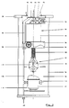
- a pole 10 of a gas-insulated high-voltage switch or circuit breaker 12 is housed in a first column isolator 14, carried by a second support isolator 16.
- the two insulators 14, 16 are cylindrical and their internal volumes communicate through openings 18, so as to form a first sealed compartment 20 filled with insulating gas, having a high dielectric strength, in particular sulfur hexafluoride SF6 under pressure.
- the pole 10 comprises a fixed contact 22, a movable contact 24 driven in translation by an actuating rod 26 made of insulating material, and an arc extinguishing device 28 made active during the separation of the contacts 22,24.
- the arc extinguishing device 28 comprises, for example, a self-blowing chamber by compression of the SF6 by means of a piston-cylinder assembly set in motion during the displacement of the actuating rod 26 between the open positions. and closing the circuit breaker 12.
- interrupting chamber can be used in the pole 10, in particular a vacuum, expansion, or magnetic blowing chamber by rotation of the arc.
- the lower end 29 of the actuating rod 26 is coupled to a pneumatic control mechanism 30 housed in a second compartment 32.
- the latter is confined in a cylindrical casing 34, sealingly fixed to a support plate 35 of the base of the second insulator 16 by an assembly device.
- the pneumatic control mechanism 30 is actuated from pressurized SF6 gas contained in the first compartment 20.
- the second sealed compartment 32 acts as a closed volume for expansion of the control gas with a pressure close to or below atmospheric pressure , while it is of the order of 6 bars in the first compartment 20.
- the joining of the two compartments 20,32 by means of the assembly device forms a unique and autonomous structure using the same SF6 gas for the isolation, arc breaking, and closing and opening control.
- connection pads 36, 38 situated at the level of the first insulator 14, and being in electrical connection respectively with the fixed contact 22, and the movable contact 24.
- the casing 34 contains an electric compressor 40, and an auxiliary contact device 42 associated with a mechanical connection 44 with neutral tumbler type passage.
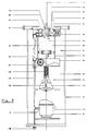
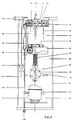
- the pneumatic control mechanism 30 is arranged in the upper part of the second compartment 32, and comprises a double-acting cylinder 46, the movable piston 48 of which is secured coaxially to the actuating rod 26 of the pole 10.
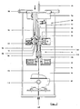
- the piston 48 of the cylinder 46 slides in a fixed cylinder 50 to ensure either the closing of the contacts 22,24 of the circuit breaker 12 by translation upwards ( Figures 7 and 8), or the opening of the contacts 22,24 by translation of the piston 48 downwards ( Figures 5 and 6).
- the upper bottom of the cylinder 50 is attached to a first distribution system 52 for the control gas, composed of a first valve 54 controlled by an opening electromagnet 56.
- the opposite bottom bottom of the cylinder 50 is supported on a second distribution system 58 fitted with a second valve 60 controlled by a closing electromagnet 62.
- the first opening control valve 54 is shaped as a drawer fitted with a pair of valves 64, 66, cooperating alternately with two fixed seats 68, 70 of the body 72 according to the active or inactive state of the electromagnet d opening 56.
- the opening electromagnet 56 is excited, and the valve 64 is separated from the corresponding seat 68 to open a first intake orifice 74.
- the other valve 66 is in engagement against the seat 70 to close a first exhaust orifice 76 between the upstream volume of the jack 46 and the expansion volume of the second compartment 32.
- the electromagnet 56 n ' is more energized ( Figure 6) causing the opening of the exhaust port 76 and closing the intake port 74.
- the body 72 is sealingly mounted inside the annular plate 35.
- the structure of the second valve 60 (FIGS. 7 and 8) is identical, but its arrangement is reversed with respect to that of the first valve 54.
- the valve 60 has two valves 78.80 capable of defining a second intake orifice 82 , and a second exhaust port 84, respectively with two corresponding seats 86, 88 of the body 90.
- the intake port 82 In the active state of excitation of the closing electromagnet 62 (FIG. 7), the intake port 82 is open, while the exhaust port 84 is closed.
- the inlet port 82 is closed, while the exhaust port 84 is open .
- the delivery of SF6 gas under pressure to the inlet ports 74, 82 of the first and second valves 54, 60 is carried out through two passage ports 92, 94 (FIGS. 2 and 3), communicating with the first compartment. 20, and located in the same plane at the level of the partition wall 35.
- the lumen 94 is arranged directly in the body 72, and is located in the vicinity of the first inlet orifice 74.
- the two gas passage openings 92, 94 cooperate with a regulating device 98 (FIGS. 2 and 3) of the gas pressure acting on the piston 48 of the jack 46, as a function of the temperature variations of the gas contained in the first compartment 20.
- the regulating device 98 comprises a rotary knob 100 fitted with a bimetallic spring 101 and two radial tabs 102, 104, having substantially the same angular offset as the two openings 92, 94.
- the button 100 is located in the first compartment 20, and the spring 101 is in the form of a spiral mounted on the axis 103 of the button 100, and its deformation reflects the variation in temperature, causing a predetermined rotation of the button 100, and the progressive or decreasing overlap of the openings 92.94 by the tabs 102.104.
- the useful pressure of the control gas in the cylinder 46 is thus adjustable to a predetermined threshold according to the environment in which the circuit breaker is located.
- the total section of the light 92 is less than that of the other light 94, so as to adapt the actuating force of the jack 46, according to the type of closing or opening control.
- the tubing 96 is connected to a pipe 106 connected to a filling orifice 108, and to the discharge orifice 110 of the compressor 40.
- the suction orifice 112 of the compressor 40 allows to draw gas at low pressure contained in the second compartment 32, as soon as the compressor 40 is started by means of a contact 114 controlled by a pressure switch 116 (FIG. 6).
- the latter is housed in the casing 34, and measures the differential pressure of the SF6 gas between the two compartments 20,32. After a closing or opening operation, the lowering of the pressure in the first compartment 20 is detected by the pressure switch 116, which closes the contact 114 supplying the compressor 40.
- the gas compressed by the compressor 40 is then discharged towards the first compartment 20 through the pipe 106, the tubing 96 and the light 92.
- the pressure switch 116 opens the contact 114 to stop the compressor 40.
- the first compartment 20 is re-inflated by the compressor 40 automatically after each closing or opening operation of the pneumatic control mechanism.
- the mechanical connection 44 to be tumbled comprises a linkage 118 with neutral passage coupled to the piston rod 48, and a compression spring 120 interposed between the fixed body 90 of the valve 60 of the second distribution system 58, and the axis upper linkage 118.
- the auxiliary contact device 42 is mechanically connected to the main axis 122 of linkage 118, and comprises contacts for signaling CAOF of the open or closed position of the circuit breaker 12, and contacts of supply of the two electromagnets 56,62 for opening and closing.
- the opening sequence of the contacts 22,24 of the circuit breaker 12 is started by excitation of the opening electromagnet 56 (FIG. 5) of the first distribution system 52.
- the first valve 54 is attracted towards the right, ensuring the opening of the first intake port 74 and the closure of the first exhaust port 76.
- the pressurized gas from the first compartment 20 fills the upstream volume of the cylinder 46 through the lumen 94 and l inlet 74, and causes the piston 48 to descend.
- the arc After separation of the contacts 22, 24, the arc generates an increase in pressure in the first compartment 20 which improves the gas supply to the jack 46 during the continued opening stroke.
- the auxiliary contact device 42 interrupts the excitation of the opening electromagnet 56.
- the first valve 54 is biased to the left and automatically returns to its position d Originally, by closing the first intake port 74 and opening the first exhaust port 76. The gas contained in the upstream volume of the jack 46 is then expelled through the exhaust port 76, towards the volume d expansion of the second compartment 32 at low pressure. Closing the inlet orifice 74 inhibits any additional entry of high-pressure gas into the cylinder 46.
- the passage from neutral of the mechanical connection 44 at the end of the piston stroke 48 generates an additional force which is added to the action of the pneumatic control mechanism 30, and which maintains the contacts 22, 24 in the open position after the electromagnet 56 is de-energized.
- the open state of the circuit breaker 12 is indicated by the CAOF signaling contacts of device 42.
- the excitation of the closing electromagnet 62 of the second distribution system 58 is inhibited, requiring the closing of the second intake port 82, and the opening of the second port. exhaust 84. Any admission of high pressure gas into the downstream volume of the cylinder 46 is made impossible during the opening phase.
- the downstream volume of the jack 46 is permanently in communication with the second compartment 32 at low pressure so as not to oppose the downward movement of the piston 48.
- the closing order of the contacts 22, 24 of the circuit breaker 12 results from the excitation of the closing electromagnet 62 (FIG. 7).
- the second valve 60 moves to the left, causing the second intake port 82 to open and the second exhaust port 84 to close.
- the high-pressure SF6 gas, coming from the first compartment 20, fills the downstream volume of the cylinder 46 through the lumen 92, the tubing 96 and the inlet port 82, and urges the piston 48 movable upwards.
- the supply of the closing electromagnet 62 is stopped by the intervention of the auxiliary contact device 42.
- the automatic return to the right of the second valve 60 closes the second intake port 82, and opens the second exhaust port 84, so as to stop the entry of high pressure gas into the cylinder 46.
- the opening of the exhaust port 84 allows the setting communication of the downstream volume of the cylinder 46 with the second compartment 32 at low pressure.
- the contacts 22, 24 are then in the closed state, and are maintained in this position after crossing the neutral point of the mechanical connection 44, which is integral with the actuating rod 26.
- the intervention of the regulating device 98 with a button 100 acts on the passage section of the two openings 92, 94 as a function of the variation in temperature of the gas detected by the bimetallic spring 101 in the first compartment 20.
- the pressure of the gas contained in the upstream volume, and in the downstream volume of the cylinder 46, after opening the corresponding intake port 74, 82, is then easily adjustable to a predetermined threshold.
- the pressure drop in the first compartment 20 is detected by the pressure switch 116, which closes the contact 114 for supplying the compressor 40 to recharge the circuit breaker 12.
- the compressor 40 sucks the SF6 gas contained in the second compartment 32 at low pressure, and discharges it after compression to the first compartment 20.
- the compressor 40 stops automatically as soon as the pressure in the compartment 20 reaches the set value (6 bars).
- the mechanism 30 is then operational for a new command.
- the double-acting piston 48 of the jack 46 of FIGS. 1 to 7 can be replaced by a jack with a differential piston. Any other insulating gas can be used in place of SF6.
- the embodiment described with reference to Figures 1 to 7 relates to a high voltage circuit breaker of the "open" type, but it is understood that the invention applies to a shielded circuit breaker.
Landscapes
- Circuit Breakers (AREA)
- Gas-Insulated Switchgears (AREA)
- Arc-Extinguishing Devices That Are Switches (AREA)
- Fluid-Pressure Circuits (AREA)
- Switches Operated By Changes In Physical Conditions (AREA)
- Percussive Tools And Related Accessories (AREA)
- Organic Insulating Materials (AREA)
Claims (9)
- Gasisolierter Hochspannungs-Leistungsschalter oder Lastschalter, der ein erstes gasdichtes, mit einem Gas hoher dielektrischer Festigkeit, insbesondere Schwefelhexafluorid gefülltes Abteil (20) aufweist, das mindestens einen Abschaltpol (10) mit zwei trennbaren Kontakten (22, 24), eine bei Trennung der Kontakte (22, 24) aktivierte Lichtbogenlöscheinrichtung (28), eine Schaltstange (26), die mit einem zur Ein- und Ausschaltung dienenden Antriebsmechanismus (30) gekoppelt ist, welcher einen Pneumatikzylinder (46) mit einem während des Einschalt- bzw. Ausschaltvorgangs durch das SF6 betätigten Kolben (48) aufweist, sowie mit dem Zylinder (46) zusammenwirkende Mittel (52, 58) zur Verteilung des SF6-Gases umfaßt, wobei der Antriebsmechanismus (30) in einem gasdichten Niederdruckbehälter (34) angeordnet ist, der ein zweites Abteil (32) bildet, welches als Ausdehnungsraum für das am Ende des Einschalt- bzw. Ausschalthubs des Kolbens (48) aus dem Zylinder (46) ausgestoßene Gas dient, dadurch gekennzeichnet, daß das zweite Abteil (32) unter dem ersten Abteil (20) angeordnet ist, daß der Pneumatikzylinder (46) durch das im ersten Abteil (20) enthaltene, unter Druck stehende SF6 betätigt wird und daß die Mittel (52, 58) zur Verteilung des Gasstroms vollständig im zweiten Abteil (32) angeordnet sind, um das Einströmen des im ersten Abteil (20) enthaltenen Druckgases in den Zylinder (46) zu ermöglichen, wenn die Ausstoßverbindung zwischen dem Zylinder (46) und dem zweiten Niederdruckabteil (32) geschlossen ist, bzw. umgekehrt die Verbindung zwischen dem Zylinder (46) und dem zweiten Abteil (32) zu ermöglichen wenn der Einlaßstrom des Druckgases unterbrochen ist.
- Leistungsschalter nach Anspruch 1, dadurch gekennzeichnet, daß die Mittel (52, 58) ein erstes, über eine Ausschaltspule (56) angesteuertes Ventil (54) sowie ein zweites, über eine Einschaltspule (62) angesteuertes Ventil (60) umfassen, wobei jedes der Ventile (54, 60) eine zwischen dem ersten Abteil (20) und dem Zylinder (46) angeordnete Einlaßöffnung (74, 82) sowie eine zwischen dem Ventil (46) und dem zweiten Abteil (32) angeordnete Auslaßöffnung (76, 84) aufweist, und daß der Druckgasstrom vom ersten Abteil (20) zu den Einlaßöffnungen (74, 82) des ersten und des zweiten Ventils (54, 60) über zwei Durchlaßöffnungen (92, 94) erfolgt, die in Höhe der zwischen dem ersten und dem zweiten Abteil (20, 32) eingefügten Trennwand (35) angeordnet sind.
- Leistungsschalter nach Anspruch 2, dadurch gekennzeichnet, daß der Querschnitt der beiden Durchlaßöffnungen (92, 94) über eine Regeleinrichtung (98) gesteuert wird, die auf die Temperaturänderungen des im ersten Abteil (20) enthaltenen Druckgases reagiert und so ausgeführt ist, daß der Betriebsdruck des Zylinders (46) bei Freigabe der jeweiligen Einlaßöffnung (74, 82) auf einen bestimmten Schwellwert eingestellt werden kann.
- Leistungsschalter nach Anspruch 3, dadurch gekennzeichnet, daß die Regeleinrichtung (98) einen Drehknopf (100) mit zwei Steuerflügeln (102, 104) umfaßt, die durch Abdeckung mit den beiden Durchgangsöffnungen (92, 94) sowie mit einer durch die Temperaturänderung des genannten Druckgases verformbaren Bimetallfeder (101) zusammenwirken.
- Leistungsschalter nach einem der Ansprüche 2 bis 4, dadurch gekennzeichnet, daß der bewegliche Kolben (48) des Pneumatikzylinders (46) im zweiten Abteil (32) mit einer mechanischen Verbindung (44) mit Wendemechanismus gekoppelt ist, die so ausgelegt ist, daß sie die Wirkung des Antriebsmechanismus (30) am Ende des Einschalt- bzw. Ausschalthubs des Kolbens (48) durch eine Zusatzkraft verstärkt, um nach der Entregung der Ausschalt- bzw. Einschaltspule (56, 62) das Halten des Leistungsschalters in der Ausschalt- bzw. Einschaltstellung zu gewährleisten.
- Leistungsschalter nach Anspruch 5, dadurch gekennzeichnet, daß die mechanische Verbindung (44) einer Hilfskontaktanordnung (42) zur Anzeige der Schaltstellung des Leistungsschalters (10) sowie zur Unterbrechung der Spannungsversorgung der Ausschaltspule (56) bzw. der Einschaltspule (62) am Ende des Hubs des Kolbens (48) zugeordnet ist.
- Leistungsschalter nach einem der Ansprüche 1 bis 6, dadurch gekennzeichnet, daß der gasdichte Behälter (34) eine Gaseinfüllöffnung (108) aufweist und einen Druckwächter (116) sowie einen Verdichter (40) mit einer, mit dem zweiten Niederdruckabteil verbundenen Ansaugöffnung (112), sowie einer, über eine Rohrverbindung (106, 96) mit dem ersten Abteil (20) verbundenen Drucköffnung (110) umschließt, wobei der genannte Druckwächter (116) dazu dient, die zwischen dem ersten und dem zweiten Abteil (20, 32) auftretende Gasdruckdifferenz zu messen, so daß nach jedem Einschalt- bzw. Ausschaltvorgang des Antriebsmechanismus' (30) der Druck im ersten Abteil (20) wieder auf seinen Sollwert erhöht werden kann.
- Leistungsschalter nach einem der Ansprüche 1 bis 7, dadurch gekennzeichnet, daß die Lichtbogenlöscheinrichtung (28) nach Trennung der Kontakte (22, 24) mit dem ersten Abteil (20) in Verbindung steht, damit der Lichtbogendruck die Gasströmung in den Pneumatikzylinder (46) zur Fortsetzung des Ausschaltvorgangs des Leistungsschalters unterstützt.
- Leistungsschalter nach Anspruch 7, dadurch gekennzeichnet, daß die Einheit aus mechanischer Verbindung (44) und Hilfskontaktanordnung (42) im Behälter (34) zwischen dem Verdichter (40) und dem Pneumatikzylinder (46) angeordnet ist, welcher ein ortsfestes Zylindergehäuse (50) umfaßt, dessen einander gegenüberliegende Böden durch die Körper (72, 90) des ersten bzw. zweiten Ventils (54, 60) abgedeckt sind.
Applications Claiming Priority (2)
| Application Number | Priority Date | Filing Date | Title |
|---|---|---|---|
| FR9008356 | 1990-06-26 | ||
| FR9008356A FR2663780B1 (fr) | 1990-06-26 | 1990-06-26 | Disjoncteur haute tension a isolement gazeux et a mecanisme de commande pneumatique. |
Publications (2)
| Publication Number | Publication Date |
|---|---|
| EP0465377A1 EP0465377A1 (de) | 1992-01-08 |
| EP0465377B1 true EP0465377B1 (de) | 1995-08-23 |
Family
ID=9398250
Family Applications (1)
| Application Number | Title | Priority Date | Filing Date |
|---|---|---|---|
| EP91420180A Expired - Lifetime EP0465377B1 (de) | 1990-06-26 | 1991-06-07 | Hochspannungsleistungsschalter mit Isoliergas und pneumatischem Steuermechanismus |
Country Status (11)
| Country | Link |
|---|---|
| US (1) | US5187339A (de) |
| EP (1) | EP0465377B1 (de) |
| JP (1) | JP3228960B2 (de) |
| CN (1) | CN1025644C (de) |
| AT (1) | ATE126927T1 (de) |
| BR (1) | BR9102668A (de) |
| CA (1) | CA2044447C (de) |
| DE (1) | DE69112303T2 (de) |
| ES (1) | ES2078483T3 (de) |
| FR (1) | FR2663780B1 (de) |
| IT (1) | IT1249204B (de) |
Families Citing this family (85)
| Publication number | Priority date | Publication date | Assignee | Title |
|---|---|---|---|---|
| JPH09282982A (ja) * | 1996-04-18 | 1997-10-31 | Hitachi Ltd | 同期式ガス開閉装置 |
| IT1283462B1 (it) * | 1996-07-19 | 1998-04-21 | Abb Adda S P A | Dispositivo oleopneumatico per il comando di interruttori elettrici |
| JP3314000B2 (ja) * | 1997-04-01 | 2002-08-12 | 株式会社日立製作所 | ガス絶縁開閉装置 |
| FR2762924B1 (fr) * | 1997-05-05 | 1999-06-11 | Schneider Electric Sa | Sectionneur a commande pneumatique pour un poste blinde a haute tension |
| IT1292453B1 (it) | 1997-07-02 | 1999-02-08 | Aeg Niederspannungstech Gmbh | Gruppo rotante di contatti per interrutttori di alta portata |
| DE19819242B4 (de) | 1998-04-29 | 2005-11-10 | Ge Power Controls Polska Sp.Z.O.O. | Thermomagnetischer Leistungsschalter |
| US6114641A (en) | 1998-05-29 | 2000-09-05 | General Electric Company | Rotary contact assembly for high ampere-rated circuit breakers |
| US6087913A (en) | 1998-11-20 | 2000-07-11 | General Electric Company | Circuit breaker mechanism for a rotary contact system |
| US6037555A (en) | 1999-01-05 | 2000-03-14 | General Electric Company | Rotary contact circuit breaker venting arrangement including current transformer |
| US6166344A (en) | 1999-03-23 | 2000-12-26 | General Electric Company | Circuit breaker handle block |
| US6262872B1 (en) | 1999-06-03 | 2001-07-17 | General Electric Company | Electronic trip unit with user-adjustable sensitivity to current spikes |
| US6268991B1 (en) | 1999-06-25 | 2001-07-31 | General Electric Company | Method and arrangement for customizing electronic circuit interrupters |
| US6218917B1 (en) | 1999-07-02 | 2001-04-17 | General Electric Company | Method and arrangement for calibration of circuit breaker thermal trip unit |
| US6188036B1 (en) | 1999-08-03 | 2001-02-13 | General Electric Company | Bottom vented circuit breaker capable of top down assembly onto equipment |
| US6710988B1 (en) | 1999-08-17 | 2004-03-23 | General Electric Company | Small-sized industrial rated electric motor starter switch unit |
| US6252365B1 (en) | 1999-08-17 | 2001-06-26 | General Electric Company | Breaker/starter with auto-configurable trip unit |
| US6396369B1 (en) | 1999-08-27 | 2002-05-28 | General Electric Company | Rotary contact assembly for high ampere-rated circuit breakers |
| US6175288B1 (en) | 1999-08-27 | 2001-01-16 | General Electric Company | Supplemental trip unit for rotary circuit interrupters |
| US6232570B1 (en) | 1999-09-16 | 2001-05-15 | General Electric Company | Arcing contact arrangement |
| US6326869B1 (en) | 1999-09-23 | 2001-12-04 | General Electric Company | Clapper armature system for a circuit breaker |
| US6239395B1 (en) | 1999-10-14 | 2001-05-29 | General Electric Company | Auxiliary position switch assembly for a circuit breaker |
| US6229413B1 (en) | 1999-10-19 | 2001-05-08 | General Electric Company | Support of stationary conductors for a circuit breaker |
| US6317018B1 (en) | 1999-10-26 | 2001-11-13 | General Electric Company | Circuit breaker mechanism |
| US6232856B1 (en) | 1999-11-02 | 2001-05-15 | General Electric Company | Magnetic shunt assembly |
| ES2249875T3 (es) | 1999-11-03 | 2006-04-01 | AEG NIEDERSPANNUNGSTECHNIK GMBH & CO. KG | Disposicion de brazo de contacto rotatorio para disyuntor. |
| US6377144B1 (en) | 1999-11-03 | 2002-04-23 | General Electric Company | Molded case circuit breaker base and mid-cover assembly |
| US6300586B1 (en) | 1999-12-09 | 2001-10-09 | General Electric Company | Arc runner retaining feature |
| US6310307B1 (en) | 1999-12-17 | 2001-10-30 | General Electric Company | Circuit breaker rotary contact arm arrangement |
| US6172584B1 (en) | 1999-12-20 | 2001-01-09 | General Electric Company | Circuit breaker accessory reset system |
| US6184761B1 (en) | 1999-12-20 | 2001-02-06 | General Electric Company | Circuit breaker rotary contact arrangement |
| US6215379B1 (en) | 1999-12-23 | 2001-04-10 | General Electric Company | Shunt for indirectly heated bimetallic strip |
| US6281461B1 (en) | 1999-12-27 | 2001-08-28 | General Electric Company | Circuit breaker rotor assembly having arc prevention structure |
| US6346869B1 (en) | 1999-12-28 | 2002-02-12 | General Electric Company | Rating plug for circuit breakers |
| US6211758B1 (en) | 2000-01-11 | 2001-04-03 | General Electric Company | Circuit breaker accessory gap control mechanism |
| US6239677B1 (en) | 2000-02-10 | 2001-05-29 | General Electric Company | Circuit breaker thermal magnetic trip unit |
| US6429759B1 (en) | 2000-02-14 | 2002-08-06 | General Electric Company | Split and angled contacts |
| US6281458B1 (en) | 2000-02-24 | 2001-08-28 | General Electric Company | Circuit breaker auxiliary magnetic trip unit with pressure sensitive release |
| US6313425B1 (en) | 2000-02-24 | 2001-11-06 | General Electric Company | Cassette assembly with rejection features |
| US6404314B1 (en) | 2000-02-29 | 2002-06-11 | General Electric Company | Adjustable trip solenoid |
| US6204743B1 (en) | 2000-02-29 | 2001-03-20 | General Electric Company | Dual connector strap for a rotary contact circuit breaker |
| US6346868B1 (en) | 2000-03-01 | 2002-02-12 | General Electric Company | Circuit interrupter operating mechanism |
| US6448521B1 (en) | 2000-03-01 | 2002-09-10 | General Electric Company | Blocking apparatus for circuit breaker contact structure |
| US6379196B1 (en) | 2000-03-01 | 2002-04-30 | General Electric Company | Terminal connector for a circuit breaker |
| US6340925B1 (en) | 2000-03-01 | 2002-01-22 | General Electric Company | Circuit breaker mechanism tripping cam |
| US6459349B1 (en) | 2000-03-06 | 2002-10-01 | General Electric Company | Circuit breaker comprising a current transformer with a partial air gap |
| US6366438B1 (en) | 2000-03-06 | 2002-04-02 | General Electric Company | Circuit interrupter rotary contact arm |
| US6211757B1 (en) | 2000-03-06 | 2001-04-03 | General Electric Company | Fast acting high force trip actuator |
| US6496347B1 (en) | 2000-03-08 | 2002-12-17 | General Electric Company | System and method for optimization of a circuit breaker mechanism |
| US6429659B1 (en) | 2000-03-09 | 2002-08-06 | General Electric Company | Connection tester for an electronic trip unit |
| US6366188B1 (en) | 2000-03-15 | 2002-04-02 | General Electric Company | Accessory and recess identification system for circuit breakers |
| US6232859B1 (en) | 2000-03-15 | 2001-05-15 | General Electric Company | Auxiliary switch mounting configuration for use in a molded case circuit breaker |
| US6218919B1 (en) | 2000-03-15 | 2001-04-17 | General Electric Company | Circuit breaker latch mechanism with decreased trip time |
| US6459059B1 (en) | 2000-03-16 | 2002-10-01 | General Electric Company | Return spring for a circuit interrupter operating mechanism |
| US6421217B1 (en) | 2000-03-16 | 2002-07-16 | General Electric Company | Circuit breaker accessory reset system |
| US6586693B2 (en) | 2000-03-17 | 2003-07-01 | General Electric Company | Self compensating latch arrangement |
| US6476698B1 (en) | 2000-03-17 | 2002-11-05 | General Electric Company | Convertible locking arrangement on breakers |
| FR2806548B1 (fr) | 2000-03-17 | 2002-08-23 | Ge Power Controls France | Mecanisme extractible pour disjoncteurs |
| US6373010B1 (en) | 2000-03-17 | 2002-04-16 | General Electric Company | Adjustable energy storage mechanism for a circuit breaker motor operator |
| US6559743B2 (en) | 2000-03-17 | 2003-05-06 | General Electric Company | Stored energy system for breaker operating mechanism |
| US6639168B1 (en) | 2000-03-17 | 2003-10-28 | General Electric Company | Energy absorbing contact arm stop |
| US6479774B1 (en) | 2000-03-17 | 2002-11-12 | General Electric Company | High energy closing mechanism for circuit breakers |
| US6388213B1 (en) | 2000-03-17 | 2002-05-14 | General Electric Company | Locking device for molded case circuit breakers |
| US6472620B2 (en) | 2000-03-17 | 2002-10-29 | Ge Power Controls France Sas | Locking arrangement for circuit breaker draw-out mechanism |
| US6747535B2 (en) | 2000-03-27 | 2004-06-08 | General Electric Company | Precision location system between actuator accessory and mechanism |
| US6373357B1 (en) | 2000-05-16 | 2002-04-16 | General Electric Company | Pressure sensitive trip mechanism for a rotary breaker |
| US6400245B1 (en) | 2000-10-13 | 2002-06-04 | General Electric Company | Draw out interlock for circuit breakers |
| US6806800B1 (en) | 2000-10-19 | 2004-10-19 | General Electric Company | Assembly for mounting a motor operator on a circuit breaker |
| US6531941B1 (en) | 2000-10-19 | 2003-03-11 | General Electric Company | Clip for a conductor in a rotary breaker |
| US6429760B1 (en) | 2000-10-19 | 2002-08-06 | General Electric Company | Cross bar for a conductor in a rotary breaker |
| US6362711B1 (en) | 2000-11-10 | 2002-03-26 | General Electric Company | Circuit breaker cover with screw locating feature |
| US6380829B1 (en) | 2000-11-21 | 2002-04-30 | General Electric Company | Motor operator interlock and method for circuit breakers |
| US6448522B1 (en) | 2001-01-30 | 2002-09-10 | General Electric Company | Compact high speed motor operator for a circuit breaker |
| US6476337B2 (en) | 2001-02-26 | 2002-11-05 | General Electric Company | Auxiliary switch actuation arrangement |
| US6882258B2 (en) * | 2001-02-27 | 2005-04-19 | General Electric Company | Mechanical bell alarm assembly for a circuit breaker |
| US6678135B2 (en) | 2001-09-12 | 2004-01-13 | General Electric Company | Module plug for an electronic trip unit |
| US6469882B1 (en) | 2001-10-31 | 2002-10-22 | General Electric Company | Current transformer initial condition correction |
| US6804101B2 (en) | 2001-11-06 | 2004-10-12 | General Electric Company | Digital rating plug for electronic trip unit in circuit breakers |
| GB0405543D0 (en) * | 2004-03-10 | 2004-04-21 | Eja Ltd | Switch mechanism |
| US7528332B1 (en) | 2004-11-17 | 2009-05-05 | Utron Inc. | High speed actuating device and circuit breaker |
| EP2648202A1 (de) | 2012-04-05 | 2013-10-09 | ABB Technology AG | Schutzschalter |
| CN103325613B (zh) * | 2013-07-04 | 2015-09-30 | 国网浙江省电力公司嵊泗县供电公司 | 一种真空断路器 |
| CN105914596B (zh) * | 2016-06-12 | 2018-05-18 | 飞策防爆电器有限公司 | 一种防爆配电柜 |
| CN108550496B (zh) * | 2018-07-02 | 2023-08-01 | 江苏双汇电力发展股份有限公司 | 10kV高压电动真空保护开关 |
| CN111917023B (zh) * | 2019-08-16 | 2022-04-19 | 重庆华美电力设备有限责任公司 | 配电箱用气动断送电与除尘装置 |
| CN112783019B (zh) * | 2020-12-10 | 2022-11-08 | 国网江苏省电力有限公司盐城供电分公司 | 一种高压断路器智能控制系统及其检测方法 |
Family Cites Families (12)
| Publication number | Priority date | Publication date | Assignee | Title |
|---|---|---|---|---|
| US3379849A (en) * | 1964-12-17 | 1968-04-23 | Westinghouse Electric Corp | Dual-pressure gas-blast circuit breaker with piston means and interrupting unit in closed tank |
| DE1640124A1 (de) * | 1965-01-21 | 1971-10-14 | Gratzmuller Jean Louis | Elektrischer Schalter |
| FR2115506A5 (de) * | 1970-11-23 | 1972-07-07 | Gratzmuller Jean Louis | |
| DE2064798B2 (de) * | 1970-12-18 | 1976-11-18 | Siemens AG, 1000 Berlin und 8000 München | Hydraulischer antrieb fuer einen elektrischen schalter |
| NL151206B (nl) * | 1971-03-05 | 1976-10-15 | Coq Bv | Eenpolig schakelveld voor een geheel beschermde elektrische verdeel- en schakelinrichting voor hoge spanning. |
| FR2272475B1 (de) * | 1974-05-20 | 1977-10-21 | Alsthom Cgee | |
| DE2707594B1 (de) * | 1977-02-18 | 1978-08-17 | Siemens Ag | Druckgasschalter |
| US4118613A (en) * | 1977-06-27 | 1978-10-03 | General Electric Company | Hydraulically-actuated operating system for an electric circuit breaker |
| US4384182A (en) * | 1980-05-29 | 1983-05-17 | General Electric Company | Hydraulic actuator for an electric circuit breaker |
| CH654444A5 (fr) * | 1981-10-12 | 1986-02-14 | Alsthom Atlantique | Disjoncteur a gaz sous pression comprenant pour chaque phase deux chambres de coupure disposees en v. |
| FR2590720B1 (fr) * | 1985-11-27 | 1988-01-15 | Merlin Gerin | Dispositif de commande d'un disjoncteur haute tension equipe de resistances de fermeture |
| DE3709988A1 (de) * | 1987-03-26 | 1988-10-06 | Bbc Brown Boveri & Cie | Hydraulischer oder pneumatischer antrieb zur betaetigung des beweglichen schaltkontaktes eines mittel- und/oder hochspannungs-leistungsschalters |
-
1990
- 1990-06-26 FR FR9008356A patent/FR2663780B1/fr not_active Expired - Fee Related
-
1991
- 1991-06-07 ES ES91420180T patent/ES2078483T3/es not_active Expired - Lifetime
- 1991-06-07 DE DE69112303T patent/DE69112303T2/de not_active Expired - Fee Related
- 1991-06-07 EP EP91420180A patent/EP0465377B1/de not_active Expired - Lifetime
- 1991-06-07 AT AT91420180T patent/ATE126927T1/de not_active IP Right Cessation
- 1991-06-12 CA CA002044447A patent/CA2044447C/en not_active Expired - Fee Related
- 1991-06-13 US US07/714,868 patent/US5187339A/en not_active Expired - Fee Related
- 1991-06-24 CN CN91104153.2A patent/CN1025644C/zh not_active Expired - Fee Related
- 1991-06-25 JP JP18029591A patent/JP3228960B2/ja not_active Expired - Fee Related
- 1991-06-25 IT ITVR910060A patent/IT1249204B/it active IP Right Grant
- 1991-06-25 BR BR919102668A patent/BR9102668A/pt not_active IP Right Cessation
Also Published As
| Publication number | Publication date |
|---|---|
| CA2044447A1 (en) | 1991-12-27 |
| ITVR910060A1 (it) | 1992-12-25 |
| FR2663780A1 (fr) | 1991-12-27 |
| IT1249204B (it) | 1995-02-20 |
| US5187339A (en) | 1993-02-16 |
| DE69112303D1 (de) | 1995-09-28 |
| CN1057733A (zh) | 1992-01-08 |
| JP3228960B2 (ja) | 2001-11-12 |
| ATE126927T1 (de) | 1995-09-15 |
| ITVR910060A0 (it) | 1991-06-25 |
| ES2078483T3 (es) | 1995-12-16 |
| JPH04229917A (ja) | 1992-08-19 |
| DE69112303T2 (de) | 1996-10-10 |
| BR9102668A (pt) | 1992-02-04 |
| CA2044447C (en) | 2000-09-05 |
| CN1025644C (zh) | 1994-08-10 |
| FR2663780B1 (fr) | 1992-09-11 |
| EP0465377A1 (de) | 1992-01-08 |
Similar Documents
| Publication | Publication Date | Title |
|---|---|---|
| EP0465377A1 (de) | Hochspannungsleistungsschalter mit Isoliergas und pneumatischem Steuermechanismus | |
| US2783338A (en) | Operating mechanism for a fluid-blast circuit breaker | |
| CA1042493A (en) | High voltage gas blast circuit interrupter | |
| EP0718861A1 (de) | Elektrischer Sicherheitsschalter | |
| US3646292A (en) | High-voltage electric circuit breaker with high-speed tripping means | |
| FR2733086A1 (fr) | Dispositif de coupure hybride a haute tension | |
| CH626745A5 (en) | High-voltage self-blasting circuit breaker | |
| EP0789928A1 (de) | Hochspannungsschalter mit selbstbeblasung | |
| EP0667633B1 (de) | Selbstbeblasener Leistungsschalter mit pneumatisch festlegbarem halbbeweglichem Kolben | |
| US2969446A (en) | Air blast circuit breakers | |
| US4264794A (en) | Circuit interrupter including arc extinguishing fluid pressurization means and pressure accumulating means | |
| FR2655768A1 (fr) | Interrupteur tripolaire a haute tension et a isolement gazeux. | |
| CH373794A (fr) | Disjoncteur à gaz comprimé comprenant au moins un contact tubulaire | |
| US3336453A (en) | Means for controlling the blast valve and contacts of a gas blast circuit breaker | |
| FR2554632A1 (fr) | Disjoncteur a autosoufflage a cliquet anti-retour debrayable | |
| US3453407A (en) | Electric circuit breaker having highpressure,low-velocity gas blast | |
| US3538281A (en) | Compressed-gas circuit interrupter with cylindrical high pressure tank supporting a spherical exhaust tank | |
| EP0580515B1 (de) | Lastschalter mit zwei konzentrischen Löschkammern | |
| AU648601B2 (en) | High-voltage circuit breaker with gas insulation and pneumatic operating mechanism | |
| FR2594591A1 (fr) | Disjoncteur a haute tension a gaz d'extinction sous pression | |
| JPS6212727B2 (de) | ||
| SU1029251A1 (ru) | Маломасл ный выключатель высокого напр жени | |
| KR820002035B1 (ko) | 2중 압축 기체 분사 퍼훠형 차단장치 | |
| FR2653266A1 (fr) | Dispositif de commande d'un disjoncteur a haute tension et a poles separes. | |
| EP0022729A1 (de) | Bistabiles hydraulisches Ventil für die Steuerung eines Kolbens eines schnellen Hochspannungs-Leistungsschalters |
Legal Events
| Date | Code | Title | Description |
|---|---|---|---|
| PUAI | Public reference made under article 153(3) epc to a published international application that has entered the european phase |
Free format text: ORIGINAL CODE: 0009012 |
|
| AK | Designated contracting states |
Kind code of ref document: A1 Designated state(s): AT BE CH DE ES GB LI SE |
|
| 17P | Request for examination filed |
Effective date: 19920603 |
|
| 17Q | First examination report despatched |
Effective date: 19940311 |
|
| RAP1 | Party data changed (applicant data changed or rights of an application transferred) |
Owner name: SCHNEIDER ELECTRIC SA |
|
| GRAA | (expected) grant |
Free format text: ORIGINAL CODE: 0009210 |
|
| AK | Designated contracting states |
Kind code of ref document: B1 Designated state(s): AT BE CH DE ES GB LI SE |
|
| REF | Corresponds to: |
Ref document number: 126927 Country of ref document: AT Date of ref document: 19950915 Kind code of ref document: T |
|
| REF | Corresponds to: |
Ref document number: 69112303 Country of ref document: DE Date of ref document: 19950928 |
|
| GBT | Gb: translation of ep patent filed (gb section 77(6)(a)/1977) |
Effective date: 19951107 |
|
| REG | Reference to a national code |
Ref country code: ES Ref legal event code: FG2A Ref document number: 2078483 Country of ref document: ES Kind code of ref document: T3 |
|
| PLBE | No opposition filed within time limit |
Free format text: ORIGINAL CODE: 0009261 |
|
| STAA | Information on the status of an ep patent application or granted ep patent |
Free format text: STATUS: NO OPPOSITION FILED WITHIN TIME LIMIT |
|
| 26N | No opposition filed | ||
| PGFP | Annual fee paid to national office [announced via postgrant information from national office to epo] |
Ref country code: GB Payment date: 20010606 Year of fee payment: 11 |
|
| PGFP | Annual fee paid to national office [announced via postgrant information from national office to epo] |
Ref country code: AT Payment date: 20010613 Year of fee payment: 11 |
|
| PGFP | Annual fee paid to national office [announced via postgrant information from national office to epo] |
Ref country code: ES Payment date: 20010629 Year of fee payment: 11 |
|
| PGFP | Annual fee paid to national office [announced via postgrant information from national office to epo] |
Ref country code: BE Payment date: 20010816 Year of fee payment: 11 |
|
| REG | Reference to a national code |
Ref country code: GB Ref legal event code: IF02 |
|
| PG25 | Lapsed in a contracting state [announced via postgrant information from national office to epo] |
Ref country code: GB Free format text: LAPSE BECAUSE OF NON-PAYMENT OF DUE FEES Effective date: 20020607 Ref country code: AT Free format text: LAPSE BECAUSE OF NON-PAYMENT OF DUE FEES Effective date: 20020607 |
|
| PG25 | Lapsed in a contracting state [announced via postgrant information from national office to epo] |
Ref country code: ES Free format text: LAPSE BECAUSE OF NON-PAYMENT OF DUE FEES Effective date: 20020608 |
|
| PG25 | Lapsed in a contracting state [announced via postgrant information from national office to epo] |
Ref country code: BE Free format text: LAPSE BECAUSE OF NON-PAYMENT OF DUE FEES Effective date: 20020630 |
|
| BERE | Be: lapsed |
Owner name: S.A. *SCHNEIDER ELECTRIC Effective date: 20020630 |
|
| GBPC | Gb: european patent ceased through non-payment of renewal fee |
Effective date: 20020607 |
|
| REG | Reference to a national code |
Ref country code: ES Ref legal event code: FD2A Effective date: 20030711 |
|
| PGFP | Annual fee paid to national office [announced via postgrant information from national office to epo] |
Ref country code: DE Payment date: 20040525 Year of fee payment: 14 |
|
| PGFP | Annual fee paid to national office [announced via postgrant information from national office to epo] |
Ref country code: SE Payment date: 20040526 Year of fee payment: 14 Ref country code: CH Payment date: 20040526 Year of fee payment: 14 |
|
| REG | Reference to a national code |
Ref country code: CH Ref legal event code: PFA Owner name: VA TECH TRANSMISSION & DISTRIBUTION SA Free format text: SCHNEIDER ELECTRIC S.A.#40, AVENUE ANDRE MORIZET#BOULOGNE BILLANCOURT (FR) -TRANSFER TO- VA TECH TRANSMISSION & DISTRIBUTION SA#1, RUE DE LA NEVA#38000 GRENOBLE (FR) Ref country code: CH Ref legal event code: NV Representative=s name: NOVAGRAAF INTERNATIONAL SA |
|
| PG25 | Lapsed in a contracting state [announced via postgrant information from national office to epo] |
Ref country code: SE Free format text: LAPSE BECAUSE OF NON-PAYMENT OF DUE FEES Effective date: 20050608 |
|
| PG25 | Lapsed in a contracting state [announced via postgrant information from national office to epo] |
Ref country code: LI Free format text: LAPSE BECAUSE OF NON-PAYMENT OF DUE FEES Effective date: 20050630 Ref country code: CH Free format text: LAPSE BECAUSE OF NON-PAYMENT OF DUE FEES Effective date: 20050630 |
|
| PG25 | Lapsed in a contracting state [announced via postgrant information from national office to epo] |
Ref country code: DE Free format text: LAPSE BECAUSE OF NON-PAYMENT OF DUE FEES Effective date: 20060103 |
|
| REG | Reference to a national code |
Ref country code: CH Ref legal event code: PL |
|
| EUG | Se: european patent has lapsed |