EP0465770A1 - Outil de meulage frontal à lamelles - Google Patents
Outil de meulage frontal à lamelles Download PDFInfo
- Publication number
- EP0465770A1 EP0465770A1 EP91105665A EP91105665A EP0465770A1 EP 0465770 A1 EP0465770 A1 EP 0465770A1 EP 91105665 A EP91105665 A EP 91105665A EP 91105665 A EP91105665 A EP 91105665A EP 0465770 A1 EP0465770 A1 EP 0465770A1
- Authority
- EP
- European Patent Office
- Prior art keywords
- carrier
- support plate
- grinding
- flap
- grinding tool
- Prior art date
- Legal status (The legal status is an assumption and is not a legal conclusion. Google has not performed a legal analysis and makes no representation as to the accuracy of the status listed.)
- Granted
Links
- 239000004744 fabric Substances 0.000 claims abstract description 15
- 239000000853 adhesive Substances 0.000 claims description 19
- 230000001070 adhesive effect Effects 0.000 claims description 15
- 239000000835 fiber Substances 0.000 claims description 3
- 230000000750 progressive effect Effects 0.000 claims 2
- 238000004026 adhesive bonding Methods 0.000 abstract 1
- 239000004033 plastic Substances 0.000 description 5
- 241000446313 Lamella Species 0.000 description 3
- 230000000694 effects Effects 0.000 description 3
- 239000003795 chemical substances by application Substances 0.000 description 2
- 239000010410 layer Substances 0.000 description 2
- 235000001674 Agaricus brunnescens Nutrition 0.000 description 1
- 239000006061 abrasive grain Substances 0.000 description 1
- 239000012790 adhesive layer Substances 0.000 description 1
- 229910052782 aluminium Inorganic materials 0.000 description 1
- XAGFODPZIPBFFR-UHFFFAOYSA-N aluminium Chemical compound [Al] XAGFODPZIPBFFR-UHFFFAOYSA-N 0.000 description 1
- 238000004873 anchoring Methods 0.000 description 1
- 238000005516 engineering process Methods 0.000 description 1
- 230000007613 environmental effect Effects 0.000 description 1
- 239000011888 foil Substances 0.000 description 1
- 238000004519 manufacturing process Methods 0.000 description 1
- 229910052751 metal Inorganic materials 0.000 description 1
- 239000002184 metal Substances 0.000 description 1
- 239000002985 plastic film Substances 0.000 description 1
- 229920006255 plastic film Polymers 0.000 description 1
- 230000001681 protective effect Effects 0.000 description 1
- 239000002699 waste material Substances 0.000 description 1
- 238000009941 weaving Methods 0.000 description 1
- 239000002759 woven fabric Substances 0.000 description 1
Images
Classifications
-
- B—PERFORMING OPERATIONS; TRANSPORTING
- B24—GRINDING; POLISHING
- B24D—TOOLS FOR GRINDING, BUFFING OR SHARPENING
- B24D13/00—Wheels having flexibly-acting working parts, e.g. buffing wheels; Mountings therefor
- B24D13/14—Wheels having flexibly-acting working parts, e.g. buffing wheels; Mountings therefor acting by the front face
- B24D13/16—Wheels having flexibly-acting working parts, e.g. buffing wheels; Mountings therefor acting by the front face comprising pleated flaps or strips
-
- B—PERFORMING OPERATIONS; TRANSPORTING
- B24—GRINDING; POLISHING
- B24D—TOOLS FOR GRINDING, BUFFING OR SHARPENING
- B24D9/00—Wheels or drums supporting in exchangeable arrangement a layer of flexible abrasive material, e.g. sandpaper
- B24D9/08—Circular back-plates for carrying flexible material
- B24D9/085—Devices for mounting sheets on a backing plate
Definitions
- the invention relates to a flap face grinding tool with a support plate, which is provided with a fastening means for mounting on a drive machine, and with a grinding wheel, which has a circular disk-shaped carrier, releasably attachable to the support plate, and radially aligned, fan-overlapping grinding flaps fastened thereon.
- Such a tool is known from US Pat. No. 3,616,581.
- the support plate has a raised ring, which is provided with a rubber covering.
- the carrier is provided with radial slots, into each of which a grinding flap is inserted in such a way that an edge protrudes on the rear side facing away from the grinding side.
- the carrier is screwed onto the support plate with a central screw, the protruding edges between the carrier and the ring area being firmly clamped in order to anchor the grinding flaps.
- the grinding lamellas are fitted on site by unscrewing the carrier, inserting the grinding lamella and then screwing the carrier back onto the support plate. The changeover times are therefore relatively long and require great care.
- front end grinding wheels which have a plastic plate provided with radial slots and a pin with a mandrel, and in which the grinding flaps are glued into the radial slots.
- the plastic plates form a waste that is difficult to dispose of.
- flap discs with a disc made of recyclable aluminum are also known, in which the grinding flaps are anchored in radial slots by mechanical clamping or fastened on a closed disc surface with adhesive.
- the invention has for its object to provide a flap tool of the type mentioned, in which the changeover times are shortened.
- the connecting means between the carrier and the support plate is a self-adhesive, releasable, large-area adhesive.
- the connecting means consists of a layer of a releasable adhesive applied on the carrier side.
- this self-adhesive layer can be covered, for example, with a removable protective film.
- the connecting means between the carrier and the support plate is a surface fastener (Velcro fastener).
- a surface fastener which is also referred to as a Velcro fastener or Velcro fastener, is understood to mean two surfaces belonging to a particular type of zip fastener with different surface effects.
- One surface is weaving technology e.g. with loose chain thread loops made of multifilament synthetics.
- the other surface has, for example, a large number of small hooks or spherical or mushroom heads on its upper side, which are formed from monofilament Velcro threads or the like. This creates a Velcro-like adhesive effect when the two tapes are placed on top of each other.
- the invention has the advantage that the carrier can be removed from the support plate in a simple manner with a movement perpendicular to the plate surface. Nevertheless, the plate is held securely in the grinding mode, since the effect of the shear forces that occur is smaller than the surface adhesion.
- a preferred embodiment of the invention is that the carrier consists of a fabric and that the grinding flaps are glued on. This has the advantage that the plate can be punched out easily and with little tool wear.
- the adhesive also forms a good bond with the fabric so that the sanding flaps are securely anchored. Furthermore, the surface fastener can be released even more easily due to the flexibility of the carrier.
- the carrier In principle, it is possible to produce the carrier from hard paper, a metal foil, a plastic film or a fabric made from plastic threads.
- the fabric consists of a natural fiber fabric. This has the further advantage that it can be treated with an impregnating agent which improves the adhesive effect and connection with the adhesive which fixes the abrasive flaps.
- the carrier can also be advantageous for the carrier to consist of several layers, so that the anchoring effect, the flexibility and the fabric openings are optimized in particular with regard to the grain size of the grinding flaps.
- the possible applications of the flap grinding tool are particularly great in that the outside diameter of the carrier and the grinding flap ring is larger than the outside diameter of the support plate. In this way, a protrusion is created that also allows grinding in corners and slots.
- This development is particularly economical, since after the outer area of the grinding flaps has been worked off and a corresponding reduction in the outer diameter, a smaller support plate can be used, so that the grinding wheel can be worked almost completely from the outside to the inside.
- a harder or softer grinding can be carried out.
- a particularly simple centering of the grinding wheel or the carrier on the support plate is achieved in that the support plate and the grinding wheel are each provided with a matching perforation. If you align both perforations one above the other, for example with the help of a separate pin, the backing plate and grinding wheel are concentric.
- the support plate is provided with a central, grinding wheel-side screw bolt or with a threaded bore and a corresponding recess for receiving the relevant counterpart. Since the surface fastener holds the grinding wheel and the screw connection essentially serves only as a safeguard against unintentional detachment in the idle state, it can be made correspondingly light.
- a particularly inexpensive manufacture of the grinding wheel is achieved in that the surface belonging to the surface fastener consists of the loose chain thread loops or a pile fabric and that the support plate-side part of the surface fastener consists of the tentacle adhesives.
- this development has the advantage that the plastic portion of the grinding wheel is further reduced.
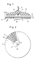
- a substantially rigid support plate 10 is provided with a central mandrel 11, with which this can be used in a screw chuck of a drive machine (not shown).
- the support plate 10 is provided over a large area with mushroom-like, elastic plastic tentacles 12, which form a surface of a surface fastener (Velcro fastener 9).
- the counter surface of the surface fastener 9 is located on a circular disk-shaped carrier 13 of a separate grinding wheel 14. This surface is formed by a pile 15 of loose warp thread loops.
- the grinding flaps 16 each consist of a fabric with a surface coated with abrasive grain. They are glued to the carrier 13 at their end faces.
- the carrier 13 is a woven fabric made of natural fibers, which is treated with an impregnating agent for a good connection with the adhesive.
- the grinding wheel 14 is flexible in itself, although in principle a rigid support is also possible.
- the outer diameter of the carrier 13 has a predetermined protrusion a compared to the outer diameter of the support plate 10, so that the flap grinding tool can not only be used for large-area grinding operation, but also corners and the like can be machined due to the protrusion.
- the support plate 10 there is a recess 17 in the center with a central threaded bolt 18 which is flush with the surface of the support plate 10.
- the threaded bolt 18 cooperates with a central perforation 19 in the carrier 13, so that a concentric arrangement of the support plate 10 and grinding wheel 14 is ensured.
- the carrier 13 or the grinding wheel 14 are fastened to the support plate 10 by first inserting the perforation 19 onto the threaded bolt 18 and then pressing the surfaces of the surface fastener 9 together.
- the tentacles 12 then adhere so firmly in the pile 15 that a safe grinding operation is possible.
- a locking nut 20 can be screwed onto the threaded bolt 18, the adjacent regions 21 (FIG. 2) of the carrier 13 being clamped in the recess 17. As a rule, such a backup should not be necessary.
- the surface fastener 9 is released in a simple manner in that the carrier 13 is pulled off in the axial direction.
- the carrier 13 is provided with radial slots 22 in the area of the perforation 19, so that the area 21 of the recess 17 of the support plate 10 can adapt when securing with the lock nut 20.
Landscapes
- Engineering & Computer Science (AREA)
- Mechanical Engineering (AREA)
- Polishing Bodies And Polishing Tools (AREA)
- Pharmaceuticals Containing Other Organic And Inorganic Compounds (AREA)
- Finish Polishing, Edge Sharpening, And Grinding By Specific Grinding Devices (AREA)
- Thermotherapy And Cooling Therapy Devices (AREA)
Applications Claiming Priority (2)
| Application Number | Priority Date | Filing Date | Title |
|---|---|---|---|
| DE4020461A DE4020461C1 (en) | 1990-06-27 | 1990-06-27 | Face grinding disc tool - has replaceable grinding disc with backing disc having plastics rods |
| DE4020461 | 1990-06-27 |
Publications (2)
| Publication Number | Publication Date |
|---|---|
| EP0465770A1 true EP0465770A1 (fr) | 1992-01-15 |
| EP0465770B1 EP0465770B1 (fr) | 1992-12-30 |
Family
ID=6409188
Family Applications (1)
| Application Number | Title | Priority Date | Filing Date |
|---|---|---|---|
| EP91105665A Expired - Lifetime EP0465770B1 (fr) | 1990-06-27 | 1991-04-10 | Outil de meulage frontal à lamelles |
Country Status (9)
| Country | Link |
|---|---|
| US (1) | US5201149A (fr) |
| EP (1) | EP0465770B1 (fr) |
| JP (1) | JP2501255B2 (fr) |
| AT (1) | ATE83963T1 (fr) |
| AU (1) | AU651978B2 (fr) |
| CA (1) | CA2045381C (fr) |
| DE (3) | DE4020461C1 (fr) |
| DK (1) | DK0465770T3 (fr) |
| ES (1) | ES2038057T3 (fr) |
Families Citing this family (52)
| Publication number | Priority date | Publication date | Assignee | Title |
|---|---|---|---|---|
| US5297366A (en) * | 1993-03-26 | 1994-03-29 | Huddleston Michael D | Self affixing sanding and buffing pads/system and apparatus |
| TW317223U (en) * | 1994-01-13 | 1997-10-01 | Minnesota Mining & Mfg | Abrasive article |
| DE69509219T2 (de) * | 1994-01-13 | 1999-09-23 | Minnesota Mining And Mfg. Co., Saint Paul | Schleifartikel, verfahren zur herstellung desselben, und schleifmaschine |
| US5785784A (en) | 1994-01-13 | 1998-07-28 | Minnesota Mining And Manufacturing Company | Abrasive articles method of making same and abrading apparatus |
| US5607345A (en) * | 1994-01-13 | 1997-03-04 | Minnesota Mining And Manufacturing Company | Abrading apparatus |
| US5505747A (en) * | 1994-01-13 | 1996-04-09 | Minnesota Mining And Manufacturing Company | Method of making an abrasive article |
| USD376744S (en) | 1994-08-03 | 1996-12-24 | Gerd Eisenblatter Gmbh | Support plate |
| US5815876A (en) * | 1995-09-01 | 1998-10-06 | Overseth; Elmo R. | Apparatus for cleaning and polishing a surface |
| US5692949A (en) * | 1995-11-17 | 1997-12-02 | Minnesota Mining And Manufacturing Company | Back-up pad for use with abrasive articles |
| WO1997027974A1 (fr) * | 1996-02-01 | 1997-08-07 | Yanase Kabushiki Kaisha | Dispositif de polissage rotatif |
| WO1998019830A1 (fr) | 1996-11-06 | 1998-05-14 | Minnesota Mining And Manufacturing Company | Ensemble a abrasifs multiple et procede correspondant |
| AU1986697A (en) | 1996-11-06 | 1998-05-29 | Minnesota Mining And Manufacturing Company | Multiple abrasive assembly and method |
| US5964006A (en) * | 1997-01-13 | 1999-10-12 | 3M Innovative Properties Company | Rotary surface treatment tool |
| US5947807A (en) * | 1997-02-28 | 1999-09-07 | Overseth; Elmo R. | Apparatus for cleaning and polishing a surface |
| USD399620S (en) | 1997-03-28 | 1998-10-13 | Minnesota Mining And Manufacturing Company | Surface treating article retainer |
| USD394530S (en) | 1997-03-28 | 1998-05-19 | Minnesota Mining And Manufacturing Company | Surface treating article retainer system |
| DE19853550C1 (de) * | 1998-11-20 | 2000-03-09 | Ver Schmirgel & Maschf | Fächerschleifscheibe |
| DE29910931U1 (de) * | 1999-06-22 | 1999-08-26 | Gerd Eisenblätter GmbH, 82538 Geretsried | Werkzeugträger |
| JP2001277139A (ja) * | 2000-04-03 | 2001-10-09 | Masafumi Suzuki | 研磨シートとその研磨シートを備えた研磨シート用バックパッド及びサンダー |
| DE20012746U1 (de) | 2000-07-22 | 2000-09-28 | Braasch Gerd | Schleifwerkzeug |
| DE10104963C1 (de) * | 2001-02-03 | 2002-01-31 | Eisenblaetter Gerd Gmbh | Schleifwerkzeug |
| US6863596B2 (en) * | 2001-05-25 | 2005-03-08 | 3M Innovative Properties Company | Abrasive article |
| US6743085B2 (en) | 2001-11-20 | 2004-06-01 | 3M Innovative Properties Company | Rotating back up abrasive disc assembly |
| US6726555B2 (en) * | 2001-12-27 | 2004-04-27 | Gerd Eisenblaetter Gmbh | Tool carrier |
| DE10357144A1 (de) * | 2003-12-06 | 2005-06-30 | Robert Bosch Gmbh | Schleifteller für eine Handschleifmaschine |
| US7892074B2 (en) * | 2008-01-30 | 2011-02-22 | 3M Innovative Properties Company | Surface modifying tool adapter using a plurality of surface modifying article inserts for use in a surface modifying system |
| US8469775B2 (en) * | 2008-07-10 | 2013-06-25 | 3M Innovative Properties Company | Conversion assemblage adaptable for use in combination with a surface modifying apparatus and method thereof |
| US20100009607A1 (en) * | 2008-07-10 | 2010-01-14 | 3M Innovative Properties Company | Conversion assemblage adaptable for use in combination with a surface modifying apparatus and method thereof |
| US20100009606A1 (en) * | 2008-07-10 | 2010-01-14 | 3M Innovative Properties Company | Conversion assemblage adaptable for use in combination with a surface modifying apparatus and method thereof |
| US8430725B2 (en) | 2008-12-19 | 2013-04-30 | Jovan Pajovic | Abrasive disc construction |
| DE102009054696A1 (de) * | 2009-12-15 | 2011-06-16 | August Rüggeberg Gmbh & Co. Kg | Fächer-Schleifscheibe für den Einsatz an stationären Schleifmaschinen |
| ES2361346A1 (es) * | 2011-02-21 | 2011-06-16 | Salinas E Hijos S.L. | Disco de láminas para pulir vidrio. |
| US20140325781A1 (en) * | 2013-05-03 | 2014-11-06 | LAMB'S Innovative Solutions, Inc. | Detailing and polishing pad |
| US9049976B2 (en) * | 2013-06-14 | 2015-06-09 | Robin O Blocker | Rotary sponge having an adjustable elongated handle |
| TWI583730B (zh) | 2014-05-29 | 2017-05-21 | 聖高拜磨料有限公司 | 具有包含聚合物材料之核的磨料製品 |
| US11957635B2 (en) | 2015-06-20 | 2024-04-16 | Therabody, Inc. | Percussive therapy device with variable amplitude |
| DE202015106711U1 (de) | 2015-12-09 | 2017-03-10 | Kolthoff Gabrovo Eood | Werkzeug für Oberflächenfeinbearbeitungen |
| US10040170B2 (en) | 2016-03-02 | 2018-08-07 | Perry D. Bechthold | Rotary sanding system |
| CN110505831B (zh) * | 2017-02-22 | 2021-07-09 | Acs工业股份有限公司 | 旋转分段式地板起蜡垫 |
| USD951470S1 (en) * | 2018-03-27 | 2022-05-10 | Therabody, Inc. | Vibration massage device |
| US12064387B2 (en) | 2018-12-26 | 2024-08-20 | Therabody, Inc. | Percussive therapy device with electrically connected attachment |
| US10940081B2 (en) | 2019-05-07 | 2021-03-09 | Theragun, Inc. | Percussive massage device with force meter |
| US11890253B2 (en) | 2018-12-26 | 2024-02-06 | Therabody, Inc. | Percussive therapy device with interchangeable modules |
| FI20195131A1 (en) * | 2019-02-20 | 2020-08-21 | Mirka Ltd | Device for changing abrasive products |
| US10611000B1 (en) * | 2019-04-16 | 2020-04-07 | Thomas E. Foster | Flexible sanding block using hook and loop fastener |
| US11813221B2 (en) | 2019-05-07 | 2023-11-14 | Therabody, Inc. | Portable percussive massage device |
| US11998504B2 (en) | 2019-05-07 | 2024-06-04 | Therabody, Inc. | Chair including percussive massage therapy |
| IT202000021739A1 (it) * | 2020-09-15 | 2022-03-15 | Pola & Massa S R L | Spazzola rotante migliorata, facilmente sostituibile, in particolare per la pulitura di piastre per circuiti stampati |
| US11857481B2 (en) | 2022-02-28 | 2024-01-02 | Therabody, Inc. | System for electrical connection of massage attachment to percussive therapy device |
| US12295900B1 (en) | 2022-12-21 | 2025-05-13 | Therabody, Inc. | Systems, methods, and devices for percussive massage therapy with voice activation |
| US12402686B2 (en) | 2023-06-14 | 2025-09-02 | Therabody, Inc. | Articles of footwear having therapeutic assemblies |
| WO2025059992A1 (fr) | 2023-09-21 | 2025-03-27 | Therabody, Inc. | Systèmes, procédés et dispositifs de massothérapie à percussion |
Citations (4)
| Publication number | Priority date | Publication date | Assignee | Title |
|---|---|---|---|---|
| US2907147A (en) * | 1957-12-23 | 1959-10-06 | F L & J C Codman Company | Radial face rotary buffing element |
| EP0005161A2 (fr) * | 1978-05-05 | 1979-11-14 | Miksa Marton | Fixation d'une feuille abrasive sur un disque de polissage |
| DE8810629U1 (de) * | 1988-08-22 | 1988-09-29 | Norddeutsche Schleifmittel-Industrie Christiansen & Co (GmbH & Co), 2000 Hamburg | Schleifvlieswerkzeug mit Kletthaftrückseite |
| DE9002385U1 (de) * | 1990-03-01 | 1990-05-03 | Wendt, Günther, 5227 Windeck | Fächerstirnschleifscheibe |
Family Cites Families (26)
| Publication number | Priority date | Publication date | Assignee | Title |
|---|---|---|---|---|
| US1869564A (en) * | 1930-03-10 | 1932-08-02 | David R Johnston | Polishing tool |
| US3139709A (en) * | 1963-04-15 | 1964-07-07 | Roy J Walters | Segmented abrasive rim disc and method for making the same |
| US3346904A (en) * | 1964-02-17 | 1967-10-17 | American Felt Co | Glass polishing head having a detachable felt pad |
| DE1577588A1 (de) * | 1966-09-23 | 1970-01-02 | Joachim Jung | Reissverbindung zum schnellen Auswechseln von Werkzeugblaettern od.dgl. |
| US3616581A (en) * | 1969-10-08 | 1971-11-02 | Gen Electric | Polishing and grinding rotary finishing tool |
| GB1370846A (en) * | 1972-02-22 | 1974-10-16 | Taf Tele Abrasive Flessibili D | Rotary abrading device |
| US3883998A (en) * | 1974-02-11 | 1975-05-20 | Minnesota Mining & Mfg | Fastening device for psa abrasive disc |
| JPS51151189U (fr) * | 1975-05-27 | 1976-12-02 | ||
| DE2820370C2 (de) * | 1978-05-10 | 1985-06-27 | Miksa Windsor Ontario Marton | Schleifblatt |
| US4263755A (en) * | 1979-10-12 | 1981-04-28 | Jack Globus | Abrasive product |
| DE8214991U1 (de) * | 1982-05-22 | 1982-12-16 | Fabritius, Hans-Josef, 4400 Münster | Schleifscheibe |
| DE8236261U1 (de) * | 1982-12-23 | 1983-06-16 | Fabritius, Hans-Josef, 4400 Münster | Insbesondere fuer schleif- und polierarbeiten einsetzbares vorsatzteil bei werkmaschinen |
| ATE29416T1 (de) * | 1982-12-24 | 1987-09-15 | Fabritius Hans Josef | Fuer schleif- und polierarbeiten einsetzbares vorsatzteil bei werkmaschinen. |
| JPS60114470A (ja) * | 1983-11-26 | 1985-06-20 | Nippon Rejibon Kk | 回転研削研磨具 |
| JPS60197373A (ja) * | 1984-03-21 | 1985-10-05 | Kazuo Takada | グラインダ用砥石 |
| DE3541348C1 (de) * | 1985-07-18 | 1987-01-02 | Gerd Eisenblaetter | Faecherstirnschleifscheibe |
| DE3541347C1 (de) * | 1985-11-22 | 1986-10-30 | Gerd 8192 Geretsried Eisenblätter | Faecherstirnschleifscheibe |
| DE8603759U1 (de) * | 1986-02-13 | 1986-04-10 | Ferraro, Vincenzo, 6430 Bad Hersfeld | Polierscheibe, vorzugsweise Polierscheibe aus Fell |
| JPH0344453Y2 (fr) * | 1986-09-30 | 1991-09-18 | ||
| JPS6416376A (en) * | 1987-07-11 | 1989-01-19 | Asahi Irryo Co Ltd | Rotary disk polishing tool |
| JPS6434676A (en) * | 1987-07-29 | 1989-02-06 | Nippon Resibon Corp | Rotary polisher |
| FR2626944B1 (fr) * | 1988-02-04 | 1992-04-03 | Henriet Jacques | Dispositif de connexion souple entre un arbre rotatif d'entrainement et un plateau tournant coaxial a l'arbre |
| DE3805719A1 (de) * | 1988-02-24 | 1989-08-31 | Guenther Wendt | Faecherstirnschleifscheibe |
| JPH01138661U (fr) * | 1988-03-18 | 1989-09-21 | ||
| JPH0215979A (ja) * | 1988-07-05 | 1990-01-19 | Yuichi Ichiguchi | 研磨具 |
| JPH0215869U (fr) * | 1988-07-18 | 1990-01-31 |
-
1990
- 1990-06-27 DE DE4020461A patent/DE4020461C1/de not_active Expired - Fee Related
-
1991
- 1991-04-10 ES ES199191105665T patent/ES2038057T3/es not_active Expired - Lifetime
- 1991-04-10 DE DE9191105665T patent/DE59100024D1/de not_active Expired - Lifetime
- 1991-04-10 EP EP91105665A patent/EP0465770B1/fr not_active Expired - Lifetime
- 1991-04-10 DK DK91105665.3T patent/DK0465770T3/da active
- 1991-04-10 AT AT91105665T patent/ATE83963T1/de not_active IP Right Cessation
- 1991-05-06 DE DE9105607U patent/DE9105607U1/de not_active Expired - Lifetime
- 1991-06-21 AU AU79177/91A patent/AU651978B2/en not_active Ceased
- 1991-06-26 JP JP3154737A patent/JP2501255B2/ja not_active Expired - Fee Related
- 1991-06-26 CA CA002045381A patent/CA2045381C/fr not_active Expired - Fee Related
- 1991-06-27 US US07/720,162 patent/US5201149A/en not_active Expired - Lifetime
Patent Citations (4)
| Publication number | Priority date | Publication date | Assignee | Title |
|---|---|---|---|---|
| US2907147A (en) * | 1957-12-23 | 1959-10-06 | F L & J C Codman Company | Radial face rotary buffing element |
| EP0005161A2 (fr) * | 1978-05-05 | 1979-11-14 | Miksa Marton | Fixation d'une feuille abrasive sur un disque de polissage |
| DE8810629U1 (de) * | 1988-08-22 | 1988-09-29 | Norddeutsche Schleifmittel-Industrie Christiansen & Co (GmbH & Co), 2000 Hamburg | Schleifvlieswerkzeug mit Kletthaftrückseite |
| DE9002385U1 (de) * | 1990-03-01 | 1990-05-03 | Wendt, Günther, 5227 Windeck | Fächerstirnschleifscheibe |
Also Published As
| Publication number | Publication date |
|---|---|
| AU651978B2 (en) | 1994-08-11 |
| EP0465770B1 (fr) | 1992-12-30 |
| JP2501255B2 (ja) | 1996-05-29 |
| JPH04226865A (ja) | 1992-08-17 |
| CA2045381A1 (fr) | 1991-12-28 |
| AU7917791A (en) | 1992-01-02 |
| ES2038057T3 (es) | 1993-07-01 |
| DE9105607U1 (de) | 1991-11-14 |
| DK0465770T3 (da) | 1993-04-05 |
| ATE83963T1 (de) | 1993-01-15 |
| CA2045381C (fr) | 1995-08-15 |
| DE59100024D1 (de) | 1993-02-11 |
| DE4020461C1 (en) | 1991-07-18 |
| US5201149A (en) | 1993-04-13 |
Similar Documents
| Publication | Publication Date | Title |
|---|---|---|
| EP0465770B1 (fr) | Outil de meulage frontal à lamelles | |
| DE69610337T2 (de) | Umdrehbares schleifkissen | |
| DE69804632T2 (de) | Befestigungsmittel und verwendung desselben zum befestigen eines blattförmiges schleif- oder poliermittel auf einem magnetischen halter | |
| DE69601684T2 (de) | Schmirgelmaschine | |
| DE19900994C2 (de) | Schleifscheibenarretiervorrichtung | |
| DE69301740T2 (de) | Schleifartikel und Verfahren | |
| US5249329A (en) | Self-centering buffer pad assembly | |
| DE69012551T2 (de) | Schleifgerät. | |
| EP0212062B1 (fr) | Machine à rectifier les surfaces | |
| EP0112405A1 (fr) | Elément d'attache utilisable dans des machines à meuler et à polir | |
| DE69926330T2 (de) | Schleifleinenhalterung | |
| DE69520143T2 (de) | Schleifblätter | |
| DE1777324A1 (de) | Schmirgelvorrichtung | |
| EP1117746B1 (fr) | Feuille auto-adh sive | |
| DE60000118T2 (de) | Stützteller für Schleifvorrichtung | |
| WO1993008955A1 (fr) | Dispositif a disque d'usinage | |
| DE69103577T2 (de) | Scheibenhalteranordnung. | |
| DE19920651A1 (de) | Rotierendes Maschinen-Schleifwerkzeug | |
| DE69007467T2 (de) | Doppelseitige Schleifscheibe mit interner Verstärkung. | |
| DE3844261A1 (de) | Mehrfach verwendbares haftelement, insbesondere ein haftend befestigbares schleif-, schmirgel- oder polierelement, bzw. schild fuer informationszwecke | |
| DE3525620C1 (de) | Fächerstirnschleifscheibe | |
| EP0807006A1 (fr) | Bande de pon age et de polissage | |
| DE2805288A1 (de) | Schleifblatt | |
| DE3030942A1 (de) | Schleifschuh, insbesondere fuer handschleifgeraete | |
| DE3633946A1 (de) | Haltekoerper fuer werkzeugblaetter |
Legal Events
| Date | Code | Title | Description |
|---|---|---|---|
| PUAI | Public reference made under article 153(3) epc to a published international application that has entered the european phase |
Free format text: ORIGINAL CODE: 0009012 |
|
| AK | Designated contracting states |
Kind code of ref document: A1 Designated state(s): AT BE CH DE DK ES FR GB IT LI NL SE |
|
| 17P | Request for examination filed |
Effective date: 19911219 |
|
| 17Q | First examination report despatched |
Effective date: 19920331 |
|
| GRAA | (expected) grant |
Free format text: ORIGINAL CODE: 0009210 |
|
| AK | Designated contracting states |
Kind code of ref document: B1 Designated state(s): AT BE CH DE DK ES FR GB IT LI NL SE |
|
| REF | Corresponds to: |
Ref document number: 83963 Country of ref document: AT Date of ref document: 19930115 Kind code of ref document: T |
|
| REF | Corresponds to: |
Ref document number: 59100024 Country of ref document: DE Date of ref document: 19930211 |
|
| ET | Fr: translation filed | ||
| ITF | It: translation for a ep patent filed | ||
| REG | Reference to a national code |
Ref country code: DK Ref legal event code: T3 |
|
| GBT | Gb: translation of ep patent filed (gb section 77(6)(a)/1977) |
Effective date: 19930317 |
|
| REG | Reference to a national code |
Ref country code: ES Ref legal event code: FG2A Ref document number: 2038057 Country of ref document: ES Kind code of ref document: T3 |
|
| PLBE | No opposition filed within time limit |
Free format text: ORIGINAL CODE: 0009261 |
|
| STAA | Information on the status of an ep patent application or granted ep patent |
Free format text: STATUS: NO OPPOSITION FILED WITHIN TIME LIMIT |
|
| 26N | No opposition filed | ||
| EAL | Se: european patent in force in sweden |
Ref document number: 91105665.3 |
|
| PGFP | Annual fee paid to national office [announced via postgrant information from national office to epo] |
Ref country code: SE Payment date: 19980415 Year of fee payment: 8 |
|
| PGFP | Annual fee paid to national office [announced via postgrant information from national office to epo] |
Ref country code: ES Payment date: 19980416 Year of fee payment: 8 |
|
| PGFP | Annual fee paid to national office [announced via postgrant information from national office to epo] |
Ref country code: DK Payment date: 19980422 Year of fee payment: 8 |
|
| PGFP | Annual fee paid to national office [announced via postgrant information from national office to epo] |
Ref country code: FR Payment date: 19980430 Year of fee payment: 8 |
|
| PG25 | Lapsed in a contracting state [announced via postgrant information from national office to epo] |
Ref country code: SE Free format text: LAPSE BECAUSE OF NON-PAYMENT OF DUE FEES Effective date: 19990411 |
|
| PG25 | Lapsed in a contracting state [announced via postgrant information from national office to epo] |
Ref country code: ES Free format text: LAPSE BECAUSE OF NON-PAYMENT OF DUE FEES Effective date: 19990412 |
|
| PG25 | Lapsed in a contracting state [announced via postgrant information from national office to epo] |
Ref country code: DK Free format text: LAPSE BECAUSE OF NON-PAYMENT OF DUE FEES Effective date: 19990430 |
|
| PG25 | Lapsed in a contracting state [announced via postgrant information from national office to epo] |
Ref country code: FR Free format text: LAPSE BECAUSE OF NON-PAYMENT OF DUE FEES Effective date: 19991231 |
|
| EUG | Se: european patent has lapsed |
Ref document number: 91105665.3 |
|
| REG | Reference to a national code |
Ref country code: FR Ref legal event code: ST |
|
| REG | Reference to a national code |
Ref country code: DK Ref legal event code: EBP |
|
| REG | Reference to a national code |
Ref country code: ES Ref legal event code: FD2A Effective date: 20010503 |
|
| REG | Reference to a national code |
Ref country code: GB Ref legal event code: IF02 |
|
| PGFP | Annual fee paid to national office [announced via postgrant information from national office to epo] |
Ref country code: CH Payment date: 20040429 Year of fee payment: 14 |
|
| PGFP | Annual fee paid to national office [announced via postgrant information from national office to epo] |
Ref country code: BE Payment date: 20040622 Year of fee payment: 14 |
|
| PGFP | Annual fee paid to national office [announced via postgrant information from national office to epo] |
Ref country code: NL Payment date: 20050316 Year of fee payment: 15 |
|
| PG25 | Lapsed in a contracting state [announced via postgrant information from national office to epo] |
Ref country code: IT Free format text: LAPSE BECAUSE OF NON-PAYMENT OF DUE FEES;WARNING: LAPSES OF ITALIAN PATENTS WITH EFFECTIVE DATE BEFORE 2007 MAY HAVE OCCURRED AT ANY TIME BEFORE 2007. THE CORRECT EFFECTIVE DATE MAY BE DIFFERENT FROM THE ONE RECORDED. Effective date: 20050410 |
|
| PGFP | Annual fee paid to national office [announced via postgrant information from national office to epo] |
Ref country code: AT Payment date: 20050419 Year of fee payment: 15 |
|
| PG25 | Lapsed in a contracting state [announced via postgrant information from national office to epo] |
Ref country code: CH Free format text: LAPSE BECAUSE OF NON-PAYMENT OF DUE FEES Effective date: 20050430 Ref country code: LI Free format text: LAPSE BECAUSE OF NON-PAYMENT OF DUE FEES Effective date: 20050430 Ref country code: BE Free format text: LAPSE BECAUSE OF NON-PAYMENT OF DUE FEES Effective date: 20050430 |
|
| BERE | Be: lapsed |
Owner name: GERD *EISENBLATTER G.M.B.H. Effective date: 20050430 |
|
| REG | Reference to a national code |
Ref country code: CH Ref legal event code: PL |
|
| PG25 | Lapsed in a contracting state [announced via postgrant information from national office to epo] |
Ref country code: AT Free format text: LAPSE BECAUSE OF NON-PAYMENT OF DUE FEES Effective date: 20060410 |
|
| PG25 | Lapsed in a contracting state [announced via postgrant information from national office to epo] |
Ref country code: NL Free format text: LAPSE BECAUSE OF NON-PAYMENT OF DUE FEES Effective date: 20061101 |
|
| NLV4 | Nl: lapsed or anulled due to non-payment of the annual fee |
Effective date: 20061101 |
|
| BERE | Be: lapsed |
Owner name: GERD *EISENBLATTER G.M.B.H. Effective date: 20050430 |
|
| PGFP | Annual fee paid to national office [announced via postgrant information from national office to epo] |
Ref country code: DE Payment date: 20100112 Year of fee payment: 20 |
|
| PGFP | Annual fee paid to national office [announced via postgrant information from national office to epo] |
Ref country code: GB Payment date: 20100426 Year of fee payment: 20 |
|
| REG | Reference to a national code |
Ref country code: DE Ref legal event code: R071 Ref document number: 59100024 Country of ref document: DE |
|
| REG | Reference to a national code |
Ref country code: GB Ref legal event code: PE20 Expiry date: 20110409 |
|
| PG25 | Lapsed in a contracting state [announced via postgrant information from national office to epo] |
Ref country code: GB Free format text: LAPSE BECAUSE OF EXPIRATION OF PROTECTION Effective date: 20110409 |
|
| PG25 | Lapsed in a contracting state [announced via postgrant information from national office to epo] |
Ref country code: DE Free format text: LAPSE BECAUSE OF EXPIRATION OF PROTECTION Effective date: 20110410 |