EP0467060A2 - Machine de découpage par électro-érosion utilisant un bras de guidage traversant la paroi arrière du réservoir de fluide de travail - Google Patents
Machine de découpage par électro-érosion utilisant un bras de guidage traversant la paroi arrière du réservoir de fluide de travail Download PDFInfo
- Publication number
- EP0467060A2 EP0467060A2 EP91109119A EP91109119A EP0467060A2 EP 0467060 A2 EP0467060 A2 EP 0467060A2 EP 91109119 A EP91109119 A EP 91109119A EP 91109119 A EP91109119 A EP 91109119A EP 0467060 A2 EP0467060 A2 EP 0467060A2
- Authority
- EP
- European Patent Office
- Prior art keywords
- guide arm
- closing part
- sealing
- rear wall
- container
- Prior art date
- Legal status (The legal status is an assumption and is not a legal conclusion. Google has not performed a legal analysis and makes no representation as to the accuracy of the status listed.)
- Granted
Links
Images


Classifications
-
- B—PERFORMING OPERATIONS; TRANSPORTING
- B23—MACHINE TOOLS; METAL-WORKING NOT OTHERWISE PROVIDED FOR
- B23H—WORKING OF METAL BY THE ACTION OF A HIGH CONCENTRATION OF ELECTRIC CURRENT ON A WORKPIECE USING AN ELECTRODE WHICH TAKES THE PLACE OF A TOOL; SUCH WORKING COMBINED WITH OTHER FORMS OF WORKING OF METAL
- B23H7/00—Processes or apparatus applicable to both electrical discharge machining and electrochemical machining
- B23H7/02—Wire-cutting
Definitions
- the invention relates to a machine for spark-erosive cutting of a workpiece clamped on a cross slide table of the machine in a processing zone thereof by means of a wire or band-shaped tool electrode which runs tensioned between an upper and a lower electrode guide, the machine having a container for at least the processing zone the working fluid surrounding the workpiece is provided, the lower electrode guide is supported on an upright of the machine by means of an elongated guide arm with a horizontal longitudinal axis, the cross slide table with two crossed slides for moving the workpiece relative to the upright either parallel to the longitudinal axis of the guide arm or in addition Is provided orthogonal horizontal direction, the container has a substantially flat, opposite the stand, vertical rear wall, which with an opening delimited by an edge is provided, the guide arm traverses this rear wall of the container at right angles at the location of the opening in the direction of its longitudinal axis, the edge of the opening of the rear wall encloses the guide arm at a distance therefrom, the container with a substantially plate-shaped, parallel to the
- a proposal known from EP-0264716 or US-4808786 provides for the guide arm to be guided through the rear wall of the container and for the seal between the guide arm and the rear wall to be ensured by means of a flexible closing part designed as a bellows.
- the disadvantage here is that such a bellows does not withstand the pressure of the working fluid when the container is filled with working fluid.
- a proposal known from US-4647747 or US-4663509 provides for the guide arm to pass through the rear wall of the container and to ensure the seal between the guide arm and rear wall by means of a horizontally movable flexible closing part which is designed as a band and can be rolled up and down at its ends is.
- the disadvantage here is that such a closing part, which functions like a roller shutter on both sides, is very complicated and expensive.
- the object of the invention is to overcome the disadvantages mentioned and, in particular, to propose a convenient and inexpensive solution in order to ensure in a machine of the type mentioned at the outset that the forces required to move the closing part do not load the guide arm in any way at right angles to its longitudinal axis, which is intended to enable high-precision machining of the workpiece while ensuring the sealing of the closing part on the rear wall of the container in order to optimally support the guide arm directly on the stand and to be able to fill the container entirely with working fluid.
- a machine of the type mentioned at the outset which is characterized in that the closing part is arranged outside the container on a side of the rear wall facing the stand, the lower of the two slides is firmly connected to the closing part and only relative to the stand is movable parallel to the longitudinal axis of the guide arm, and the upper slide relative to the lower slide only at right angles to the longitudinal axis the guide arm is movable.
- a major advantage of the machine according to the invention is that the forces required to move the closing part in no way load the guide arm at right angles to its longitudinal axis, which enables high-precision machining of the workpiece.
- the closing part can preferably be provided in its lower region on its side facing the container with a channel provided with a drainage connection.
- the channel can preferably be designed as a connecting element which firmly supports the closing part on the lower slide.
- the first sealing means for the sliding seal between the closing part and the rear wall can preferably comprise at least two sealing parts arranged at a distance from one another. At least one sealing part can preferably be inflatable by gas pressure. Also, preferably a plurality of sealing parts can be integrally connected to a sealing body and molded thereon as a curved projection, the sealing body preferably being able to form a labyrinth seal together with the sealing parts formed thereon.
- the second sealing means for the sliding seal between the guide arm and the closing part in a first embodiment, comprise at least one bellows, which encloses the guide arm over at least part of its length, one end of the bellows with the guide arm and the other end of the Bellows is sealingly connected to the closing part.
- the second sealing means for the sliding seal between the guide arm and the closing part in a second embodiment, between the guide arm and the closing part, a sleeve part which is fixedly arranged on a side of the closing part facing the stand and surrounds the guide arm with play, and at least comprise two sealing parts arranged within the sleeve part at a distance from one another, sealingly and slidably enclosing the guide arm, the sleeve part cooperating at least with the two seal parts and the guide arm in order to define a sealing space enclosing the guide arm.
- the seal space can preferably be placed under gas pressure.
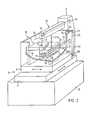
- a machine according to the invention for spark-erosive cutting of a workpiece 1 by means of a wire or band-shaped tool electrode 2 comprises a machine bed 3 and a stand 4. On the machine bed 3 there is a cross-slide table 5 with two slides 6, 7 lying one on top of the other.
- the upper slide 6 is provided with a clamping device 8 for the workpiece 1 and it is slidably displaceable and adjustably supported on the lower slide 6. This, in turn, is slidably slidable and adjustable supported on the machine bed 3.
- the tool electrode 2 is guided through a processing zone 9 of the workpiece 1 clamped on the cross slide table 5.
- the tool electrode 2 runs between egg ner over the workpiece 1 arranged upper electrode guide 10 and a lower electrode guide 11 arranged under the workpiece 1 clamped.
- the upper electrode guide 10 is supported on the stand 4 via an upper guide arm 12 and the lower electrode guide 11 via a lower guide arm 13.
- the two guide arms 12 and 13 are elongated and have a horizontal longitudinal axis 14 and 15, in other configurations at least the lower guide arm 13 is designed in this way.
- the tool electrode 2 is withdrawn from a supply spool (not shown), deflected via at least one upper roller 16, from there it is successively guided to the upper electrode guide 10, the processing zone 9 and the lower electrode guide 11, then deflected via at least one lower roller 17 and then to not shown Waste disposed of, for example wound up or chopped up.
- the direction of displacement of the lower carriage 7 is oriented parallel to the horizontal longitudinal axis 15 of the lower guide arm 13, while the direction of displacement of the upper carriage 6 is oriented in a horizontal direction orthogonal to this longitudinal axis 15.
- the lower slide 7 relative to the stand 4 can only be moved parallel to the longitudinal axis 15 of the guide arm 13 and the upper slide 6 relative to the lower slide 7 only perpendicular to the longitudinal axis 15 of the guide arm 13, while the displacement of the workpiece 1 with the aid of the cross slide table 5 relative to the stand 1 always in a horizontal plane but optionally in the direction parallel to the longitudinal axis 15 of the lower guide arm 13 as well as in the orthogonal horizontal direction and in any combination of these directions.
- the machine is provided with a container 18 for a working fluid.
- the container 18 is supported on the upper carriage 6 and encloses the clamping device 8 in such a way that the workpiece 1 or at least its processing zone 9 is surrounded by the working fluid when the container 18 is filled with working fluid.
- the container 18 has a substantially flat, opposite the stand 4, vertical rear wall 19 which is fixedly connected to the upper carriage 6.
- the lower guide arm 13 crosses this rear wall 19 of the container 18 at right angles at the location of an opening 20a (FIG. 1) or 20b (FIG. 2) in the direction of its longitudinal axis 15.
- the opening 20a or 20b is delimited by an edge 21a (FIG. 1) or 21b (FIG. 2) which encloses the lower guide arm 13 at a distance from it.
- the edge 21 of the opening 20a has the geometric shape of a continuous, convex, closed curve, which corresponds approximately to a rectangle enlarged with semicircles attached to its two vertical short sides.
- the edge 21b of the opening 20b has the geometric shape of an approximately U-shaped curve segment, which can be derived from the geometric shape of the edge 21a of the opening 20a in FIG. 1 by moving the above part of the rear wall 19 of the container 18 located in the opening 20a. 4, however, applies to both training courses.
- a closing part 22 is provided on the container 18, which is essentially plate-shaped at least in the region of the opening 20a or 20b.
- This plate part 23 of the closing part 22 is, as can be seen in particular in FIGS. 3 and 4, arranged and displaceable outside the container 18 parallel and at a short distance to a side 26 of the rear wall 19 facing the stand 4.
- the entire closing part 22 is, as can be seen particularly in FIG. 3, firmly connected to the lower slide 7.
- the dimension of the plate part 23 is selected such that it always opens 20a or 20b of the rear wall 19, i.e. covered in every displacement position.
- the plate part 23 and the rear wall 19 have approximately the same horizontal extent and this horizontal extent is at least twice the diameter of the lower guide arm 13 larger than the greatest horizontal width of the opening 20a or 20b, as in particular 4 can be seen.
- the plate part 23 in the embodiment according to FIG. 1 is at least twice and in the embodiment according to FIGS. 2 and 3 at least once the diameter of the lower guide arm 13 larger than the greatest vertical width of the opening 20a .
- first sealing means 32 are provided, which are described in more detail below.
- a major advantage of the designs according to FIGS. 1 and 2 is that the forces required to move the closing part in no way make the guide arm perpendicular to its longitudinal load the axis, which enables high-precision machining of the workpiece.
- the lower guide arm 13 In order to feed the tool electrode 2 to the machining zone 9, the lower guide arm 13 passes through the plate part 23 of the closing part 22 at right angles in the direction of its longitudinal axis 15 at the location of another opening 24 in the plate part 23 of the closing part 22.
- This other opening 24 is provided by another edge 25 limited, which sealingly surrounds the lower guide arm 13 in a manner displaceable in the direction of its longitudinal axis 15.
- second sealing means are provided, which are described in more detail below.
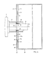
- the first sealing means 32 in a first embodiment shown in FIG. 5 comprise at least two, or, as in the embodiments shown, four spaced-apart sealing parts 34, which are indicated schematically in FIG. 4 and are shown in Fig. 5 larger and schematically in cross section.
- the sealing parts 34 are tubular and can be inflated by gas pressure or air pressure (this is not shown in detail because such inflatable seals are known per se).
- the four sealing parts 34 are integrally connected to a sealing body 35 and molded thereon as a curved projection. Together with the sealing parts 34 formed thereon, the sealing body 35 forms a labyrinth seal which is known per se and is made from an elastic plastic which is usually used for sealing purposes.
- This labyrinth seal 34, 35 has a geometric shape which corresponds to the geometric shape of the edge 21 a or 21 b of the opening 20a or 20b (FIG. 1 or FIG. 2).
- the labyrinth seal 34, 35 thus has the geometric shape of a continuous convex closed curve in the embodiment according to FIG. 1 like the edge 21 of the opening 20a, and the geometric shape in the embodiment according to FIGS. 2 and 3 like the edge 21b of the opening 20b an approximately U-shaped curve segment.
- the first sealing means 32 in a second embodiment shown in FIG. 6 comprise a U-shaped profile 42 which is arranged on the side 26 of the rear wall 19 facing the stand 4.
- This U-shaped profile 42 is thus located between the side 26 of the rear wall 19 facing the stand 4 and the side 27 of the plate part 23 of the closing part 22 facing the container 18.
- a sliding part 43 of, for example, is in the U-shaped profile 42 rectangular cross section used.
- the sliding part 43 is, for example, made of a PTFE matrix loaded with graphite and provides a sliding seal on the side 27 of the plate part 23 when it is pressed against it.
- the part of the sliding part 43 inserted into the U-shaped profile 42 defines in the U-shaped profile 42 a cavity 44 into which a seal 45 is inserted.
- Compressed air can be supplied in the cavity 44 remaining between the U-shaped profile 42 and the seal 45 in a manner not shown.
- the pressure of this compressed air exerts a force on the seal 45 in the direction of the closing part 22.
- This causes the seal 45 to be pressed against the sliding part 43 and, in turn, against the side 27 of the plate part 23 of the closing part 22.
- the container 18 is slidably sealed on the closing part 22.
- the closing part 22 is provided in its lower region on its side 27 facing the container 18 with a groove 28 which catches the working fluid which could possibly leak through the sealing means 32.
- This channel 28 serves at the same time as a connecting element for the firm support of the plate part 23 and thus the entire closing part 22 on the lower slide 7.
- the channel 28 is provided with a drainage connection 29, which is connected to lines (not shown) which lead away the working fluid is.
- the second sealing means in a first embodiment can comprise an inner bellows 30 and / or an outer bellows 31, which encloses the guide arm 13 over at least part of its length.
- One end of the bellows 30 and / or 31 is connected to the guide arm 13 in a sealing manner, for example by gluing or by tight reclamping.
- the other end of the bellows 30 and / or 31 is not shown with the closing part 22, for example by gluing or with the help of a ten, screwed on the closing part 22 flange sealed.
- means known per se and therefore not shown, such as drainage connections, are provided, which are connected to lines (not shown) that lead away the working liquid.
- the second sealing means in a second embodiment can be designed as a sealing device 33 arranged between the guide arm 13 and the closing part 22.
- This sealing device 33 comprises a sleeve part 36 which is fixedly arranged on a side 37 of the closing part 22 facing the stand 4, for example by screwing or gluing.
- the sleeve part 36 surrounds the guide arm 13 with play in order to make room for at least two sealing parts 38 which are arranged at a distance from one another within the sleeve part 36 and sealingly and slidably enclosing the guide arm 13.For example, and as shown schematically in cross section in FIG.
- Sealing parts 38 are provided which are integrally connected to a sealing body 39 and are integrally formed thereon as an annular inner projection.
- the annular sealing parts 38 enclose the guide arm 13 in a sealing and slidable manner.
- a sealing space 40 is defined between the guide arm 13, the sealing body 39 supported on the sleeve part 36 and a pair of sealing parts 38, which encloses the guide arm 13 and can be placed under gas pressure (this is not shown in detail because such seals which can be placed under gas pressure) are known).
- the sealing body 39 forms a labyrinth seal which is known per se and is made from an elastic plastic which is usually used for sealing purposes.
- an approximately U-shaped clamp 41 can hold the plate part 23 on the rear wall 19 of the container 18.
- the clip 41 is fastened to the rear wall 19 of the container 18, for example by screwing or gluing, and allows the plate part 23 to slide past, for example with the aid of a sliding body 46 made of low-friction, for example graphite-containing elastic plastic.
Landscapes
- Chemical & Material Sciences (AREA)
- Chemical Kinetics & Catalysis (AREA)
- Electrochemistry (AREA)
- Engineering & Computer Science (AREA)
- Mechanical Engineering (AREA)
- Electrical Discharge Machining, Electrochemical Machining, And Combined Machining (AREA)
Applications Claiming Priority (2)
| Application Number | Priority Date | Filing Date | Title |
|---|---|---|---|
| DE4019662 | 1990-06-20 | ||
| DE4019662A DE4019662C2 (de) | 1990-06-20 | 1990-06-20 | Maschine zum funkenerosiven Schneiden mit einem die Rückwand des Arbeitsflüssigkeits-Behälters durchquerenden Führungsarm |
Publications (3)
| Publication Number | Publication Date |
|---|---|
| EP0467060A2 true EP0467060A2 (fr) | 1992-01-22 |
| EP0467060A3 EP0467060A3 (en) | 1992-05-27 |
| EP0467060B1 EP0467060B1 (fr) | 1994-10-26 |
Family
ID=6408728
Family Applications (1)
| Application Number | Title | Priority Date | Filing Date |
|---|---|---|---|
| EP91109119A Expired - Lifetime EP0467060B1 (fr) | 1990-06-20 | 1991-06-04 | Machine de découpage par électro-érosion utilisant un bras de guidage traversant la paroi arrière du réservoir de fluide de travail |
Country Status (6)
| Country | Link |
|---|---|
| US (1) | US5111016A (fr) |
| EP (1) | EP0467060B1 (fr) |
| JP (1) | JP3026120B2 (fr) |
| KR (1) | KR0163439B1 (fr) |
| CN (1) | CN1027052C (fr) |
| DE (2) | DE4019662C2 (fr) |
Cited By (2)
| Publication number | Priority date | Publication date | Assignee | Title |
|---|---|---|---|---|
| US6486429B1 (en) | 1999-07-13 | 2002-11-26 | Agie Sa | Electric discharge machine and module set for assembly of machine tools |
| EP1716957A3 (fr) * | 2005-04-25 | 2007-01-17 | Fanuc Ltd | Dispositif d'étanchéité pour une machine à usiner par électroérosion |
Families Citing this family (14)
| Publication number | Priority date | Publication date | Assignee | Title |
|---|---|---|---|---|
| EP0610974B1 (fr) * | 1990-10-26 | 1998-03-18 | Sodick Co., Ltd. | Appareil de découpe par fil, par électro-érosion |
| JP2691487B2 (ja) * | 1992-01-18 | 1997-12-17 | ファナック株式会社 | ワイヤカット放電加工装置 |
| ES1034074Y (es) * | 1996-05-06 | 1997-05-01 | Ona Electro Erosion | Dispositivo de semi-estanqueidad entre elementos moviles en maquinas de electroerosion. |
| JP4004666B2 (ja) * | 1998-10-12 | 2007-11-07 | 株式会社ソディック | ワイヤカット放電加工機 |
| TW479587U (en) * | 2000-01-13 | 2002-03-11 | Castek Mechatron Industry Co L | Leakage proof device for the working tank of a wire cutting machine |
| JP2001277049A (ja) * | 2000-03-30 | 2001-10-09 | Brother Ind Ltd | ワイヤ放電加工機 |
| CN100462174C (zh) * | 2004-12-31 | 2009-02-18 | 广东工业大学 | 超大厚度金属材料的复合切割装置 |
| EP2552653A4 (fr) * | 2010-03-26 | 2013-12-11 | Perfect Point Edm Corp | Dispositifs et procédés d'étanchéité d'outil à main |
| JP5291771B2 (ja) * | 2011-09-06 | 2013-09-18 | ファナック株式会社 | ワイヤカット放電加工機のプレシール装置 |
| DE112012007087B4 (de) | 2012-10-30 | 2022-10-20 | Mitsubishi Electric Corporation | Elektrische Drahtentladungsbearbeitungsvorrichtung |
| CN106141340A (zh) | 2015-04-24 | 2016-11-23 | 通用电气公司 | 轮廓加工方法及用该方法加工的零件 |
| CN109676813B (zh) * | 2019-02-18 | 2024-05-10 | 泰州市江洲数控机床制造有限公司 | 砂线切割机床工件摆动切割装置 |
| CN113020731A (zh) * | 2021-03-30 | 2021-06-25 | 济南新宇硬质合金有限公司 | 一种智能化电火花切割机床 |
| CN121464011A (zh) * | 2023-11-24 | 2026-02-03 | 三菱电机株式会社 | 线放电加工机 |
Family Cites Families (13)
| Publication number | Priority date | Publication date | Assignee | Title |
|---|---|---|---|---|
| US4029929A (en) * | 1975-01-27 | 1977-06-14 | Colt Industries Operating Corporation | Electrical discharge machining device for cutting with wire electrode |
| US4363509A (en) * | 1978-04-28 | 1982-12-14 | Columbus Mckinnon Corporation | Chain grab hook providing for a flat lay cross-over link |
| CH632693A5 (fr) * | 1979-12-21 | 1982-10-29 | Charmilles Sa Ateliers | Machine pour decouper par etincelage erosif. |
| DE3303758A1 (de) * | 1983-02-04 | 1984-08-09 | Schiess Ag | Funkenerosionsmaschine |
| CH654777A5 (fr) * | 1983-07-27 | 1986-03-14 | Charmilles Sa Ateliers | Machine pour decouper par electro-erosion. |
| JPS60186319A (ja) * | 1984-02-29 | 1985-09-21 | Brother Ind Ltd | ワイヤ−カツト放電加工機 |
| JPS60186326A (ja) * | 1984-03-06 | 1985-09-21 | Brother Ind Ltd | ワイヤ−カツト放電加工機におけるワイヤ−電極案内装置 |
| KR900009029B1 (ko) * | 1986-10-07 | 1990-12-17 | 미쓰비시덴기 가부시기가이샤 | 와이어 방전 가공장치 |
| CH673248A5 (fr) * | 1987-08-28 | 1990-02-28 | Charmilles Technologies | |
| JPH01264721A (ja) * | 1988-04-14 | 1989-10-23 | Hoden Seimitsu Kako Kenkyusho Ltd | ワイヤ放電加工機 |
| JPH01306130A (ja) * | 1988-05-31 | 1989-12-11 | Hoden Seimitsu Kako Kenkyusho Ltd | シール装置 |
| JPH0739056B2 (ja) * | 1988-10-17 | 1995-05-01 | 三菱電機株式会社 | ワイヤ放電加工装置 |
| JPH0724169Y2 (ja) * | 1989-01-27 | 1995-06-05 | 三菱電機株式会社 | ワイヤ放電加工装置 |
-
1990
- 1990-06-20 DE DE4019662A patent/DE4019662C2/de not_active Expired - Fee Related
-
1991
- 1991-06-03 US US07/710,029 patent/US5111016A/en not_active Expired - Lifetime
- 1991-06-04 DE DE59103325T patent/DE59103325D1/de not_active Expired - Fee Related
- 1991-06-04 EP EP91109119A patent/EP0467060B1/fr not_active Expired - Lifetime
- 1991-06-19 JP JP3173313A patent/JP3026120B2/ja not_active Expired - Fee Related
- 1991-06-19 KR KR1019910010223A patent/KR0163439B1/ko not_active Expired - Fee Related
- 1991-06-20 CN CN91104330A patent/CN1027052C/zh not_active Expired - Fee Related
Cited By (2)
| Publication number | Priority date | Publication date | Assignee | Title |
|---|---|---|---|---|
| US6486429B1 (en) | 1999-07-13 | 2002-11-26 | Agie Sa | Electric discharge machine and module set for assembly of machine tools |
| EP1716957A3 (fr) * | 2005-04-25 | 2007-01-17 | Fanuc Ltd | Dispositif d'étanchéité pour une machine à usiner par électroérosion |
Also Published As
| Publication number | Publication date |
|---|---|
| EP0467060A3 (en) | 1992-05-27 |
| DE4019662A1 (de) | 1992-01-09 |
| KR0163439B1 (ko) | 1998-12-15 |
| JPH04226835A (ja) | 1992-08-17 |
| CN1027052C (zh) | 1994-12-21 |
| EP0467060B1 (fr) | 1994-10-26 |
| CN1057419A (zh) | 1992-01-01 |
| US5111016A (en) | 1992-05-05 |
| KR920000421A (ko) | 1992-01-29 |
| DE4019662C2 (de) | 1994-07-14 |
| DE59103325D1 (de) | 1994-12-01 |
| JP3026120B2 (ja) | 2000-03-27 |
Similar Documents
| Publication | Publication Date | Title |
|---|---|---|
| EP0467060A2 (fr) | Machine de découpage par électro-érosion utilisant un bras de guidage traversant la paroi arrière du réservoir de fluide de travail | |
| DE3636891C2 (fr) | ||
| DE10216043A1 (de) | Leitungsführungseinheit zur aktiven Führung von Leitungen, Kabeln oder dergleichen | |
| DE9316052U1 (de) | Rohrbiegemaschine | |
| DE60218339T2 (de) | Rohrbiegemaschine und links- und/oder rechtsbiegevorrichtung | |
| CH671612A5 (fr) | ||
| DE3738251A1 (de) | Drahtschneidende elektrische entladungsbearbeitungsvorrichtung | |
| DE69129124T2 (de) | Funkenerosive Drahtschneideinrichtung | |
| EP0257182A2 (fr) | Cintreuse pour tubes | |
| EP0111439B1 (fr) | Elément de construction allongé à longueur variable | |
| EP0186793A2 (fr) | Machine d'électro-érosion à table de travail fixe et bac d'usinage escamotable | |
| DE2747860C2 (de) | Schiebergehäuse für Absperrschieber | |
| DE19814615C1 (de) | Verstellbarer oberer Spannrahmen für die Formstation einer Thermoformmaschine | |
| DE2509485A1 (de) | Mehrwegeventil fuer mit schlaeuchen ausgeruestete medizinischen geraete, chemische geraete o.dgl. | |
| EP0010260A2 (fr) | Serre-joints | |
| DE2900699A1 (de) | Vorrichtung zum feinregulieren des durchflusses einer fluessigkeit und zum stabilisieren der stroemungsgeschwindigkeit der fluessigkeit | |
| DE3625074C2 (fr) | ||
| EP0036038B1 (fr) | Raccord pour les extrémités de deux conduits d'air polygonaux | |
| DE3414155C2 (fr) | ||
| DE3834974C2 (de) | Absperrschieber | |
| CH689188A5 (de) | Verfahren zum Transport eines Folienstreifens und Transportanlage fuer Folienstreifen. | |
| DE69225557T2 (de) | Kabelleiter | |
| DE19607968A1 (de) | Behandlungsliege | |
| CH651358A5 (de) | Vorrichtung zur befestigung eines laenglichen teils an einem maschinen- oder geraeteteil. | |
| DE2232970C2 (de) | Endklammer zur Sicherung von KLemmenblöcken auf einer Schiene |
Legal Events
| Date | Code | Title | Description |
|---|---|---|---|
| PUAI | Public reference made under article 153(3) epc to a published international application that has entered the european phase |
Free format text: ORIGINAL CODE: 0009012 |
|
| AK | Designated contracting states |
Kind code of ref document: A2 Designated state(s): CH DE FR GB IT LI LU SE |
|
| PUAL | Search report despatched |
Free format text: ORIGINAL CODE: 0009013 |
|
| AK | Designated contracting states |
Kind code of ref document: A3 Designated state(s): CH DE FR GB IT LI LU SE |
|
| 17P | Request for examination filed |
Effective date: 19921117 |
|
| 17Q | First examination report despatched |
Effective date: 19930511 |
|
| ITF | It: translation for a ep patent filed | ||
| GRAA | (expected) grant |
Free format text: ORIGINAL CODE: 0009210 |
|
| AK | Designated contracting states |
Kind code of ref document: B1 Designated state(s): CH DE FR GB IT LI LU SE |
|
| ET | Fr: translation filed | ||
| REF | Corresponds to: |
Ref document number: 59103325 Country of ref document: DE Date of ref document: 19941201 |
|
| GBT | Gb: translation of ep patent filed (gb section 77(6)(a)/1977) |
Effective date: 19941111 |
|
| EAL | Se: european patent in force in sweden |
Ref document number: 91109119.7 |
|
| PGFP | Annual fee paid to national office [announced via postgrant information from national office to epo] |
Ref country code: SE Payment date: 19950615 Year of fee payment: 5 |
|
| PG25 | Lapsed in a contracting state [announced via postgrant information from national office to epo] |
Ref country code: LU Free format text: LAPSE BECAUSE OF NON-PAYMENT OF DUE FEES Effective date: 19950630 |
|
| PLBE | No opposition filed within time limit |
Free format text: ORIGINAL CODE: 0009261 |
|
| STAA | Information on the status of an ep patent application or granted ep patent |
Free format text: STATUS: NO OPPOSITION FILED WITHIN TIME LIMIT |
|
| 26N | No opposition filed | ||
| PG25 | Lapsed in a contracting state [announced via postgrant information from national office to epo] |
Ref country code: SE Effective date: 19960605 |
|
| EUG | Se: european patent has lapsed |
Ref document number: 91109119.7 |
|
| REG | Reference to a national code |
Ref country code: GB Ref legal event code: IF02 |
|
| PGFP | Annual fee paid to national office [announced via postgrant information from national office to epo] |
Ref country code: CH Payment date: 20080613 Year of fee payment: 18 |
|
| PGFP | Annual fee paid to national office [announced via postgrant information from national office to epo] |
Ref country code: IT Payment date: 20080625 Year of fee payment: 18 |
|
| PGFP | Annual fee paid to national office [announced via postgrant information from national office to epo] |
Ref country code: DE Payment date: 20080620 Year of fee payment: 18 |
|
| PGFP | Annual fee paid to national office [announced via postgrant information from national office to epo] |
Ref country code: FR Payment date: 20080613 Year of fee payment: 18 |
|
| PGFP | Annual fee paid to national office [announced via postgrant information from national office to epo] |
Ref country code: GB Payment date: 20080620 Year of fee payment: 18 |
|
| REG | Reference to a national code |
Ref country code: CH Ref legal event code: PL |
|
| GBPC | Gb: european patent ceased through non-payment of renewal fee |
Effective date: 20090604 |
|
| REG | Reference to a national code |
Ref country code: FR Ref legal event code: ST Effective date: 20100226 |
|
| PG25 | Lapsed in a contracting state [announced via postgrant information from national office to epo] |
Ref country code: CH Free format text: LAPSE BECAUSE OF NON-PAYMENT OF DUE FEES Effective date: 20090630 Ref country code: LI Free format text: LAPSE BECAUSE OF NON-PAYMENT OF DUE FEES Effective date: 20090630 Ref country code: FR Free format text: LAPSE BECAUSE OF NON-PAYMENT OF DUE FEES Effective date: 20090630 |
|
| PG25 | Lapsed in a contracting state [announced via postgrant information from national office to epo] |
Ref country code: GB Free format text: LAPSE BECAUSE OF NON-PAYMENT OF DUE FEES Effective date: 20090604 |
|
| PG25 | Lapsed in a contracting state [announced via postgrant information from national office to epo] |
Ref country code: DE Free format text: LAPSE BECAUSE OF NON-PAYMENT OF DUE FEES Effective date: 20100101 |
|
| PG25 | Lapsed in a contracting state [announced via postgrant information from national office to epo] |
Ref country code: IT Free format text: LAPSE BECAUSE OF NON-PAYMENT OF DUE FEES Effective date: 20090604 |