EP0467162A1 - Verfahren zur Herstellung von Spund- und Weithalsfässern - Google Patents
Verfahren zur Herstellung von Spund- und Weithalsfässern Download PDFInfo
- Publication number
- EP0467162A1 EP0467162A1 EP91111114A EP91111114A EP0467162A1 EP 0467162 A1 EP0467162 A1 EP 0467162A1 EP 91111114 A EP91111114 A EP 91111114A EP 91111114 A EP91111114 A EP 91111114A EP 0467162 A1 EP0467162 A1 EP 0467162A1
- Authority
- EP
- European Patent Office
- Prior art keywords
- barrel
- lid
- cooling
- plastic
- bodies
- Prior art date
- Legal status (The legal status is an assumption and is not a legal conclusion. Google has not performed a legal analysis and makes no representation as to the accuracy of the status listed.)
- Granted
Links
- 238000004519 manufacturing process Methods 0.000 title claims abstract description 44
- 238000000034 method Methods 0.000 title claims abstract description 17
- 238000001816 cooling Methods 0.000 claims abstract description 56
- 239000004033 plastic Substances 0.000 claims abstract description 42
- 238000001746 injection moulding Methods 0.000 claims abstract description 30
- 238000003466 welding Methods 0.000 claims abstract description 20
- 238000000071 blow moulding Methods 0.000 claims abstract description 15
- 150000001875 compounds Chemical class 0.000 claims abstract description 4
- 238000007789 sealing Methods 0.000 claims abstract description 4
- 238000005520 cutting process Methods 0.000 claims description 24
- 238000007664 blowing Methods 0.000 claims description 13
- 238000012545 processing Methods 0.000 claims description 8
- 241000237858 Gastropoda Species 0.000 claims description 6
- 238000001035 drying Methods 0.000 claims description 5
- 238000002347 injection Methods 0.000 claims description 5
- 239000007924 injection Substances 0.000 claims description 5
- 239000002985 plastic film Substances 0.000 claims description 4
- 239000002131 composite material Substances 0.000 claims description 3
- 238000010438 heat treatment Methods 0.000 claims description 3
- 229920006255 plastic film Polymers 0.000 claims description 3
- 239000003566 sealing material Substances 0.000 claims description 2
- 229920001169 thermoplastic Polymers 0.000 claims 2
- 239000004416 thermosoftening plastic Substances 0.000 claims 2
- 238000009434 installation Methods 0.000 claims 1
- 238000002360 preparation method Methods 0.000 claims 1
- 239000008187 granular material Substances 0.000 description 7
- 230000032258 transport Effects 0.000 description 7
- 239000002699 waste material Substances 0.000 description 4
- 238000005507 spraying Methods 0.000 description 3
- 238000003860 storage Methods 0.000 description 3
- XAGFODPZIPBFFR-UHFFFAOYSA-N aluminium Chemical compound [Al] XAGFODPZIPBFFR-UHFFFAOYSA-N 0.000 description 2
- 229910052782 aluminium Inorganic materials 0.000 description 2
- 238000012432 intermediate storage Methods 0.000 description 2
- 239000000203 mixture Substances 0.000 description 2
- 238000000926 separation method Methods 0.000 description 2
- 238000005303 weighing Methods 0.000 description 2
- 238000010276 construction Methods 0.000 description 1
- 238000010924 continuous production Methods 0.000 description 1
- 230000002950 deficient Effects 0.000 description 1
- 238000007599 discharging Methods 0.000 description 1
- 230000017525 heat dissipation Effects 0.000 description 1
- 230000010354 integration Effects 0.000 description 1
- 238000003754 machining Methods 0.000 description 1
- 238000004806 packaging method and process Methods 0.000 description 1
- 239000004848 polyfunctional curative Substances 0.000 description 1
- 239000002994 raw material Substances 0.000 description 1
- 238000012958 reprocessing Methods 0.000 description 1
- 230000000284 resting effect Effects 0.000 description 1
- 239000000565 sealant Substances 0.000 description 1
- 239000012815 thermoplastic material Substances 0.000 description 1
Images



Classifications
-
- B—PERFORMING OPERATIONS; TRANSPORTING
- B29—WORKING OF PLASTICS; WORKING OF SUBSTANCES IN A PLASTIC STATE IN GENERAL
- B29C—SHAPING OR JOINING OF PLASTICS; SHAPING OF MATERIAL IN A PLASTIC STATE, NOT OTHERWISE PROVIDED FOR; AFTER-TREATMENT OF THE SHAPED PRODUCTS, e.g. REPAIRING
- B29C69/00—Combinations of shaping techniques not provided for in a single one of main groups B29C39/00 - B29C67/00, e.g. associations of moulding and joining techniques; Apparatus therefore
-
- B—PERFORMING OPERATIONS; TRANSPORTING
- B29—WORKING OF PLASTICS; WORKING OF SUBSTANCES IN A PLASTIC STATE IN GENERAL
- B29C—SHAPING OR JOINING OF PLASTICS; SHAPING OF MATERIAL IN A PLASTIC STATE, NOT OTHERWISE PROVIDED FOR; AFTER-TREATMENT OF THE SHAPED PRODUCTS, e.g. REPAIRING
- B29C31/00—Handling, e.g. feeding of the material to be shaped, storage of plastics material before moulding; Automation, i.e. automated handling lines in plastics processing plants, e.g. using manipulators or robots
- B29C31/002—Handling tubes, e.g. transferring between shaping stations, loading on mandrels
-
- B—PERFORMING OPERATIONS; TRANSPORTING
- B29—WORKING OF PLASTICS; WORKING OF SUBSTANCES IN A PLASTIC STATE IN GENERAL
- B29C—SHAPING OR JOINING OF PLASTICS; SHAPING OF MATERIAL IN A PLASTIC STATE, NOT OTHERWISE PROVIDED FOR; AFTER-TREATMENT OF THE SHAPED PRODUCTS, e.g. REPAIRING
- B29C57/00—Shaping of tube ends, e.g. flanging, belling or closing; Apparatus therefor, e.g. collapsible mandrels
-
- B—PERFORMING OPERATIONS; TRANSPORTING
- B29—WORKING OF PLASTICS; WORKING OF SUBSTANCES IN A PLASTIC STATE IN GENERAL
- B29D—PRODUCING PARTICULAR ARTICLES FROM PLASTICS OR FROM SUBSTANCES IN A PLASTIC STATE
- B29D22/00—Producing hollow articles
-
- B—PERFORMING OPERATIONS; TRANSPORTING
- B29—WORKING OF PLASTICS; WORKING OF SUBSTANCES IN A PLASTIC STATE IN GENERAL
- B29C—SHAPING OR JOINING OF PLASTICS; SHAPING OF MATERIAL IN A PLASTIC STATE, NOT OTHERWISE PROVIDED FOR; AFTER-TREATMENT OF THE SHAPED PRODUCTS, e.g. REPAIRING
- B29C45/00—Injection moulding, i.e. forcing the required volume of moulding material through a nozzle into a closed mould; Apparatus therefor
-
- B—PERFORMING OPERATIONS; TRANSPORTING
- B29—WORKING OF PLASTICS; WORKING OF SUBSTANCES IN A PLASTIC STATE IN GENERAL
- B29C—SHAPING OR JOINING OF PLASTICS; SHAPING OF MATERIAL IN A PLASTIC STATE, NOT OTHERWISE PROVIDED FOR; AFTER-TREATMENT OF THE SHAPED PRODUCTS, e.g. REPAIRING
- B29C48/00—Extrusion moulding, i.e. expressing the moulding material through a die or nozzle which imparts the desired form; Apparatus therefor
-
- B—PERFORMING OPERATIONS; TRANSPORTING
- B29—WORKING OF PLASTICS; WORKING OF SUBSTANCES IN A PLASTIC STATE IN GENERAL
- B29C—SHAPING OR JOINING OF PLASTICS; SHAPING OF MATERIAL IN A PLASTIC STATE, NOT OTHERWISE PROVIDED FOR; AFTER-TREATMENT OF THE SHAPED PRODUCTS, e.g. REPAIRING
- B29C48/00—Extrusion moulding, i.e. expressing the moulding material through a die or nozzle which imparts the desired form; Apparatus therefor
- B29C48/001—Combinations of extrusion moulding with other shaping operations
-
- B—PERFORMING OPERATIONS; TRANSPORTING
- B29—WORKING OF PLASTICS; WORKING OF SUBSTANCES IN A PLASTIC STATE IN GENERAL
- B29C—SHAPING OR JOINING OF PLASTICS; SHAPING OF MATERIAL IN A PLASTIC STATE, NOT OTHERWISE PROVIDED FOR; AFTER-TREATMENT OF THE SHAPED PRODUCTS, e.g. REPAIRING
- B29C48/00—Extrusion moulding, i.e. expressing the moulding material through a die or nozzle which imparts the desired form; Apparatus therefor
- B29C48/001—Combinations of extrusion moulding with other shaping operations
- B29C48/0017—Combinations of extrusion moulding with other shaping operations combined with blow-moulding or thermoforming
-
- B—PERFORMING OPERATIONS; TRANSPORTING
- B29—WORKING OF PLASTICS; WORKING OF SUBSTANCES IN A PLASTIC STATE IN GENERAL
- B29C—SHAPING OR JOINING OF PLASTICS; SHAPING OF MATERIAL IN A PLASTIC STATE, NOT OTHERWISE PROVIDED FOR; AFTER-TREATMENT OF THE SHAPED PRODUCTS, e.g. REPAIRING
- B29C48/00—Extrusion moulding, i.e. expressing the moulding material through a die or nozzle which imparts the desired form; Apparatus therefor
- B29C48/03—Extrusion moulding, i.e. expressing the moulding material through a die or nozzle which imparts the desired form; Apparatus therefor characterised by the shape of the extruded material at extrusion
- B29C48/05—Filamentary, e.g. strands
-
- B—PERFORMING OPERATIONS; TRANSPORTING
- B29—WORKING OF PLASTICS; WORKING OF SUBSTANCES IN A PLASTIC STATE IN GENERAL
- B29C—SHAPING OR JOINING OF PLASTICS; SHAPING OF MATERIAL IN A PLASTIC STATE, NOT OTHERWISE PROVIDED FOR; AFTER-TREATMENT OF THE SHAPED PRODUCTS, e.g. REPAIRING
- B29C48/00—Extrusion moulding, i.e. expressing the moulding material through a die or nozzle which imparts the desired form; Apparatus therefor
- B29C48/03—Extrusion moulding, i.e. expressing the moulding material through a die or nozzle which imparts the desired form; Apparatus therefor characterised by the shape of the extruded material at extrusion
- B29C48/07—Flat, e.g. panels
- B29C48/08—Flat, e.g. panels flexible, e.g. films
-
- B—PERFORMING OPERATIONS; TRANSPORTING
- B29—WORKING OF PLASTICS; WORKING OF SUBSTANCES IN A PLASTIC STATE IN GENERAL
- B29C—SHAPING OR JOINING OF PLASTICS; SHAPING OF MATERIAL IN A PLASTIC STATE, NOT OTHERWISE PROVIDED FOR; AFTER-TREATMENT OF THE SHAPED PRODUCTS, e.g. REPAIRING
- B29C65/00—Joining or sealing of preformed parts, e.g. welding of plastics materials; Apparatus therefor
-
- B—PERFORMING OPERATIONS; TRANSPORTING
- B29—WORKING OF PLASTICS; WORKING OF SUBSTANCES IN A PLASTIC STATE IN GENERAL
- B29C—SHAPING OR JOINING OF PLASTICS; SHAPING OF MATERIAL IN A PLASTIC STATE, NOT OTHERWISE PROVIDED FOR; AFTER-TREATMENT OF THE SHAPED PRODUCTS, e.g. REPAIRING
- B29C66/00—General aspects of processes or apparatus for joining preformed parts
- B29C66/50—General aspects of joining tubular articles; General aspects of joining long products, i.e. bars or profiled elements; General aspects of joining single elements to tubular articles, hollow articles or bars; General aspects of joining several hollow-preforms to form hollow or tubular articles
- B29C66/51—Joining tubular articles, profiled elements or bars; Joining single elements to tubular articles, hollow articles or bars; Joining several hollow-preforms to form hollow or tubular articles
- B29C66/53—Joining single elements to tubular articles, hollow articles or bars
- B29C66/534—Joining single elements to open ends of tubular or hollow articles or to the ends of bars
- B29C66/5346—Joining single elements to open ends of tubular or hollow articles or to the ends of bars said single elements being substantially flat
- B29C66/53461—Joining single elements to open ends of tubular or hollow articles or to the ends of bars said single elements being substantially flat joining substantially flat covers and/or substantially flat bottoms to open ends of container bodies
-
- B—PERFORMING OPERATIONS; TRANSPORTING
- B29—WORKING OF PLASTICS; WORKING OF SUBSTANCES IN A PLASTIC STATE IN GENERAL
- B29L—INDEXING SCHEME ASSOCIATED WITH SUBCLASS B29C, RELATING TO PARTICULAR ARTICLES
- B29L2031/00—Other particular articles
- B29L2031/712—Containers; Packaging elements or accessories, Packages
- B29L2031/7154—Barrels, drums, tuns, vats
-
- Y—GENERAL TAGGING OF NEW TECHNOLOGICAL DEVELOPMENTS; GENERAL TAGGING OF CROSS-SECTIONAL TECHNOLOGIES SPANNING OVER SEVERAL SECTIONS OF THE IPC; TECHNICAL SUBJECTS COVERED BY FORMER USPC CROSS-REFERENCE ART COLLECTIONS [XRACs] AND DIGESTS
- Y10—TECHNICAL SUBJECTS COVERED BY FORMER USPC
- Y10T—TECHNICAL SUBJECTS COVERED BY FORMER US CLASSIFICATION
- Y10T156/00—Adhesive bonding and miscellaneous chemical manufacture
- Y10T156/10—Methods of surface bonding and/or assembly therefor
- Y10T156/1052—Methods of surface bonding and/or assembly therefor with cutting, punching, tearing or severing
- Y10T156/108—Flash, trim or excess removal
-
- Y—GENERAL TAGGING OF NEW TECHNOLOGICAL DEVELOPMENTS; GENERAL TAGGING OF CROSS-SECTIONAL TECHNOLOGIES SPANNING OVER SEVERAL SECTIONS OF THE IPC; TECHNICAL SUBJECTS COVERED BY FORMER USPC CROSS-REFERENCE ART COLLECTIONS [XRACs] AND DIGESTS
- Y10—TECHNICAL SUBJECTS COVERED BY FORMER USPC
- Y10T—TECHNICAL SUBJECTS COVERED BY FORMER US CLASSIFICATION
- Y10T156/00—Adhesive bonding and miscellaneous chemical manufacture
- Y10T156/12—Surface bonding means and/or assembly means with cutting, punching, piercing, severing or tearing
- Y10T156/125—Plural severing means each acting on a different work piece
-
- Y—GENERAL TAGGING OF NEW TECHNOLOGICAL DEVELOPMENTS; GENERAL TAGGING OF CROSS-SECTIONAL TECHNOLOGIES SPANNING OVER SEVERAL SECTIONS OF THE IPC; TECHNICAL SUBJECTS COVERED BY FORMER USPC CROSS-REFERENCE ART COLLECTIONS [XRACs] AND DIGESTS
- Y10—TECHNICAL SUBJECTS COVERED BY FORMER USPC
- Y10T—TECHNICAL SUBJECTS COVERED BY FORMER US CLASSIFICATION
- Y10T156/00—Adhesive bonding and miscellaneous chemical manufacture
- Y10T156/12—Surface bonding means and/or assembly means with cutting, punching, piercing, severing or tearing
- Y10T156/1317—Means feeding plural workpieces to be joined
-
- Y—GENERAL TAGGING OF NEW TECHNOLOGICAL DEVELOPMENTS; GENERAL TAGGING OF CROSS-SECTIONAL TECHNOLOGIES SPANNING OVER SEVERAL SECTIONS OF THE IPC; TECHNICAL SUBJECTS COVERED BY FORMER USPC CROSS-REFERENCE ART COLLECTIONS [XRACs] AND DIGESTS
- Y10—TECHNICAL SUBJECTS COVERED BY FORMER USPC
- Y10T—TECHNICAL SUBJECTS COVERED BY FORMER US CLASSIFICATION
- Y10T156/00—Adhesive bonding and miscellaneous chemical manufacture
- Y10T156/12—Surface bonding means and/or assembly means with cutting, punching, piercing, severing or tearing
- Y10T156/1317—Means feeding plural workpieces to be joined
- Y10T156/1322—Severing before bonding or assembling of parts
-
- Y—GENERAL TAGGING OF NEW TECHNOLOGICAL DEVELOPMENTS; GENERAL TAGGING OF CROSS-SECTIONAL TECHNOLOGIES SPANNING OVER SEVERAL SECTIONS OF THE IPC; TECHNICAL SUBJECTS COVERED BY FORMER USPC CROSS-REFERENCE ART COLLECTIONS [XRACs] AND DIGESTS
- Y10—TECHNICAL SUBJECTS COVERED BY FORMER USPC
- Y10T—TECHNICAL SUBJECTS COVERED BY FORMER US CLASSIFICATION
- Y10T156/00—Adhesive bonding and miscellaneous chemical manufacture
- Y10T156/12—Surface bonding means and/or assembly means with cutting, punching, piercing, severing or tearing
- Y10T156/1317—Means feeding plural workpieces to be joined
- Y10T156/1322—Severing before bonding or assembling of parts
- Y10T156/1339—Delivering cut part in sequence to serially conveyed articles
-
- Y—GENERAL TAGGING OF NEW TECHNOLOGICAL DEVELOPMENTS; GENERAL TAGGING OF CROSS-SECTIONAL TECHNOLOGIES SPANNING OVER SEVERAL SECTIONS OF THE IPC; TECHNICAL SUBJECTS COVERED BY FORMER USPC CROSS-REFERENCE ART COLLECTIONS [XRACs] AND DIGESTS
- Y10—TECHNICAL SUBJECTS COVERED BY FORMER USPC
- Y10T—TECHNICAL SUBJECTS COVERED BY FORMER US CLASSIFICATION
- Y10T156/00—Adhesive bonding and miscellaneous chemical manufacture
- Y10T156/17—Surface bonding means and/or assemblymeans with work feeding or handling means
- Y10T156/1702—For plural parts or plural areas of single part
- Y10T156/1744—Means bringing discrete articles into assembled relationship
Definitions
- the invention relates to methods for the production of sheet drums and wide neck drums made of thermoplastic material.
- the invention has for its object to develop methods for the production of bung and wide-necked barrels made of plastic, which ensure the dimensional accuracy of the molded lid and blown barrel body, and to create systems with these production processes with higher production output.
- a method for producing sheet drums which is characterized by blowing double barrel bodies made of plastic and separating them centrally into two barrel bodies, the injection molding of sheet covers from plastic, cooling the barrel bodies and the sheet covers to fit in a cooling manner. and calibration sections which are arranged downstream of the blow molding machine for producing the double barrel bodies and the injection molding machine for the barrel lids, and the welding of the sheet piling to the barrel bodies.
- Another essential process feature of the bungie barrel production is that the sheet piling is injected with an oversize of the lower edge of the lid and that after passing through the cooling and calibration section, the ring section of the lower lid edge protruding beyond the nominal height dimension of the lid for preparing a welding surface on the lower lid edge without cutting off the oxide skin that forms when the lid is sprayed.
- the weld area is heated to remove welding stresses by flame.
- the method according to the invention for producing wide-neck drums which is provided according to the invention to achieve the object, sees the blowing of double barrel bodies made of plastic and the central separation of the same into two barrel bodies, each with a molded-on border below the barrel opening, the injection molding of barrel lids made of plastic with one at the bottom edge of the lid molded outer flange, the cooling of the barrel body and the barrel lid to fit in cooling and calibration sections, which are subordinate to the blow molding machine for producing the double barrel body and the injection molding machine for the barrel lid, the injection of a plastic sealant into the lid and the placement of the lid on the Barrel body and closing the lid with a clamping ring in front.
- the main idea of the invention can be seen in the two methods for the production of sheet drums and wide-neck drums in cooling the barrel body and the barrel lid to fit in the blow molding machine for producing the double barrel body and the injection molding machine for cooling and calibration sections arranged downstream of the barrel lid.
- This manufacturing measure in the context of an ongoing production process creates the prerequisites for the precise welding of sheet piling and barrel body in bung barrel production and a precise fitting of the lid on the barrel body in the manufacture of wide-neck barrels, ensures a significant improvement in the quality of the barrels and lowers the reject rate Minimum.
- Main components of the system according to FIGS. 1 to 3 for the production of sheet drums are a machine 1 for blowing double barrel bodies 2 made of plastic, a cutting device 3 for the central separation of the double barrel bodies 2 into two barrel bodies 4, an injection molding machine 5 for producing the sheet piling 6 made of plastic, the blow molding machine 1 and the injection molding machine 5 downstream cooling and calibration sections 7, 8 for the barrel body 4 and the bung 6, a processing machine 9 connected to the cooling and calibration section 8 for the bung 6 for cutting the lower edge of the cover to size and cutting off the slugs from injection in the injection molding machine 5, two welding machines 10 for welding the sheet piling 6 to the barrel bodies 4, a machine 11 for machining the weld seam, a device 12 for heating the weld seam area of the sheet piles 13 by means of a flame, a device 14 for checking the tightness of the sheet piles 13, a marking device 15 Cross conveyor 1 6 for discharging the defective sheet drums, a packaging device 17 and a conveyor belt removal station 18.
- the double barrel body 2 produced in the blow molding machine 1 from a plastic granulate are transported by a robot 19 to the cutting device 3, in which the double barrel body 2 is divided into two identical barrel bodies 4 by cutting out a central ring which contains the blow opening of the injection blow-in mandrel.
- the drum body 4 is brought by the robot 19 from the cutting device 3 to a weighing device 20.
- Barrel bodies with excess weight are sorted out and transferred by the robot 19 to a conveyor belt 21, which feeds the overweight barrel bodies together with the rings produced in the cutting device 3 as waste product to a cutting mill 22, the conveyor belt 21 serving as a cooling section for the temperatures of 60 to 70 ° C waste material is used.
- a suction device 23 conveys the granulate produced in the cutting mill 22 into regrind silos 24.
- the regrind from the silos 24 is mixed with fresh granulate from the raw material silos 25, and the granulate mixture is fed to the blowing machine 1.
- the robot 19 brings the barrel body 4 with the correct weight to the cooling and calibration
- the cooling and calibration section 7 has a lower endless conveyor 26 with cooling and calibration bases 27 for receiving the barrel bodies 4 in the top position 4 'and an upper endless conveyor 28 with pressure plates 29 for holding the barrel bodies 4 on the calibration bases 27, whereby the endless conveyors 26, 28 are designed as chain conveyors.
- the lower endless conveyor 26 is advanced in the feed area 30 and removal area 31 over the ends of the upper endless conveyor 28, so that there is enough space in the feed area 30 for the robot 19 to place a barrel body 4 in the top position 4 'on a calibration base 27 before a pressure plate 29 of the upper endless conveyor 28 lies on the barrel bottom 32.
- a longitudinal conveyor 35 designed as a chain conveyor takes over the barrel bodies 4, which are now transverse to the conveying direction, from the cross conveyor 34 and transports them to two mirror welding machines 10 arranged one behind the other.
- the barrel bodies 4 entering the cooling and calibration section 7 with a jacket temperature of approx. 50-60 ° C. are conveyed from holding station to holding station through the cooling and calibration section 7 in cycles over a period of approx. 30 minutes and cooled to room temperature.
- the barrel bodies 4 are blown with cooling air in the holding stations located one behind the other.
- the heat removal from the barrel bodies is mainly caused by convection and heat dissipation via the calibration base 27 and the pressure plates 29 made of aluminum with a high coefficient of thermal conductivity.
- the cooling of the barrel body 4 on the calibration base 27 ensures that the diameter of the opening edge of the barrel body 4 leaving the cooling and calibration section 7 corresponds to the diameter of the lower edge of the sheet cap 6 injected in the injection molding machine 5 after it has reached that of the injection molding machine 5 have passed downstream cooling and calibration section 8.
- the structure and mode of operation of the cooling and calibration section 8, to which the sheet covers 6 injected in the injection molding machine 5 are transferred by a robot 36, are analogous to the structure and the mode of operation of the cooling and calibration section 7 for the barrel body 4.
- the cooling and calibration section 8 according to FIG. 3 has a lower endless conveyor 37 with lower cooling and calibration plates 38 and an upper endless conveyor 39 with upper cooling and calibration plates 40 for clamping the Sheet cap 6.
- the endless conveyors 37, 39 are designed as chain conveyors.
- the cooling and calibration plates 38, 40 are made of aluminum.
- the slugs originating from spraying are removed from the sheet covers 6 and the ring section of the lower cover edge protruding beyond the nominal height dimension of the sheet covers is injected with an oversize to prepare a welding surface at the lower cover edge without the oxide skin that forms when the lid is sprayed is cut off.
- the slugs and rings are transferred to the conveyor belt 21 by means of a conveyor belt 41 and are conveyed from there to the cutting mill 22 together with the waste products resulting from the blowing and separating of the double barrel bodies 2.
- Two portal linear robots 42, 43 transport the sheet piling 6 from the processing machine 9 to the two mirror welding machines 10, in which the sheet piling 6 is welded to the barrel bodies 4 coming from the cooling and calibration section 7 in a precisely fitting manner.
- a longitudinal conveyor 44 designed as a chain conveyor transports the bung 13 from the mirror welding machines 10 to the processing machine 11, which cuts off the protruding weld seam of the bung, and from there via the device 12 for heating the weld area of the bung by means of a flame to remove welding stresses to a turning device 45, which transfers the sheet drums in an upright position to another, longitudinal conveyor belt 46.
- the conveyor belt 46 transports the sheet drums 13 further to the testing device 14, in which the drums are checked for leaks, from there to the marking device 15, in which the drums receive a serial production number and a company logo, past the cross conveyor 16 to discharge the faulty ones Barrels to the assembly device 17, in which the bungs are closed with threaded plugs and the barrels are optionally further customized, and from there to the removal station 18 at the end of the conveyor belt 46.
- the finished sheet piles are preferably placed on pallets in a palletizing device, not shown, before being transported to the customer, which can be packed into units of several pallets in a subsequent stretching device, also not shown.
- the main components of the system according to FIG. 4 for the production of wide-neck drums are a machine 47 for blowing double barrel bodies 48 made of plastic, a cutting device 49 for separating the double barrel bodies 48 in the center into two barrel bodies 50, each with a border molded onto it at a distance below the barrel opening, and an injection molding machine 51 for the production of the drum cover 52 made of plastic, the blow molding machine 47 and the injection molding machine 51 downstream cooling and calibration sections 53, 54 for the drum body 50 and the drum cover 52, a machine 55 for separating the slugs from the drum cover 52, a machine 56 for injecting one Plastic sealing material in the cover 52 and a drying device 57 arranged downstream of this and an assembly stand 58 for placing the cover 52 on the barrel body 50 and closing the cover with a clamping ring.
- the barrel bodies 50 on the assembly stand 58 are equipped with a flexible inliner made of a plastic film or a metal-plastic composite film.
- the double barrel bodies 48 produced in the blow molding machine 47 from a plastic granulate are transported by a robot 59 to the cutting device 49, in which the double barrel bodies 48 are divided into two identical barrel bodies 50.
- the drum body 50 is brought by the robot 59 from the cutting device 49 to a weighing device 60. Barrel bodies with excess weight are sorted out and transferred by the robot 59 to a conveyor belt 61, which feeds the overweight barrel bodies together with the plastic rings produced in the cutting device 49 to a cutting mill 62.
- a suction device 63 conveys the granulate produced in the cutting mill 62 in regrind silos 64 for reprocessing in a mixture with fresh granulate.
- the robot 59 brings the barrel body 50 with the prescribed weight to the cooling and calibration section 53, the structure and mode of operation of which correspond to the construction and the mode of operation of the cooling and calibration section 7 of the above-described plant for the production of bung-type drums.
- the barrel body 50 After passing through the cooling and calibrating section 53, the barrel body 50 becomes one Transfer and removal device 65 to a conveyor belt 66 which brings the barrel body to the assembly stand 58.
- the covers 52 leaving the injection molding machine 51 are taken over by a robot 67 and introduced into the cooling and calibration section 54, which corresponds to the cooling and calibration section 8 of the above-described plant for the production of bung-type drums.
- the processing machine 55 adjoining the cooling and calibration section 54 the slugs molded onto the cover 52 are cut off, which are transported from the blow molding machine 47 into the cutting mill 62 together with the waste produced in the cutting device 49 and the reject barrels.
- the barrel lid 52 is transferred from the processing machine 55 into the injection molding machine 56, with which a two-component plastic sealing compound is injected into the lid.
- the covers are transported with a conveyor belt 68 into the drying device 57, in which the reaction between the plastic sealing compound and an admixed hardener, which is initiated on the transport route between the injection molding machine and the drying device, is completed.
- the drum covers 52 removed from the drying device 57 are placed on the drum bodies 50 — possibly after inserting an inliner — and the drum covers are closed with a clamping ring.
- the finished wide-neck drums 69 are palletized after signing, and the pallets with the drums can be packed into units of several pallets as required.
Landscapes
- Engineering & Computer Science (AREA)
- Mechanical Engineering (AREA)
- Robotics (AREA)
- Blow-Moulding Or Thermoforming Of Plastics Or The Like (AREA)
- Injection Moulding Of Plastics Or The Like (AREA)
- Lining Or Joining Of Plastics Or The Like (AREA)
- Processing And Handling Of Plastics And Other Materials For Molding In General (AREA)
- Spinning Methods And Devices For Manufacturing Artificial Fibers (AREA)
- Tents Or Canopies (AREA)
- Yarns And Mechanical Finishing Of Yarns Or Ropes (AREA)
- Paper (AREA)
- Low-Molecular Organic Synthesis Reactions Using Catalysts (AREA)
- Two-Way Televisions, Distribution Of Moving Picture Or The Like (AREA)
- Organic Low-Molecular-Weight Compounds And Preparation Thereof (AREA)
- Closures For Containers (AREA)
- Glass Compositions (AREA)
Abstract
Description
- Die Erfindung betrifft verfahren zur Herstellung von Spundfässern und Weithalsfässern aus thermoplastischem Kunststoff.
- Das Aufsetzen der aus Kunststoff gespritzten Deckel, die zwischengelagert werden, auf die aus Kunststoff geblasenen Faßkörper bei der Herstellung von Weithalsfässern ist oft mit Schwierigkeiten verbunden, weil Deckel und Faßkörper wegen der bei der Kunststoffverarbeitung auftretenden, von verschiedenen Faktoren abhängigen Maßabweichungen der Kunststoffteile, vornehmlich das unterschiedliche Schwinden der Kunststoffteile beim Abkühlen nach dem Blasen und Spritzen der Teile, nicht genau zusammenpassen.
- Die Problematik der mangelnden Maßhaltigkeit der miteinander zu verbindenden Kunststoffteile tritt auch bei der Herstellung von Spundfässern aus Kunststoff auf, bei der der geblasene Faßmantel mit dem Spunddeckel und dem Boden, die in Spritzgießmaschinen hergestellt und zwischengelagert werden, verschweißt wird.
- Die mangelnde Maßhaltigkeit der Kunststoffteile führt bei der Herstellung von Spundfässern und von Weithalsfässern zu einer verhältnismäßig hohen Ausschußrate. Ein weiterer Nachteil bei der Fertigung von Spund- und Weithalsfässern aus Kunststoff ist in dem fehlenden Produktionsfluß zu sehen, bedingt durch die Zwischenlagerung der Deckel und Böden, die durch den benötigten Lagerraum und den erforderlichen inner- oder zwischenbetrieblichen Transport der Deckel und Böden von den Spritzgießmaschinen zum Lager und von dort zur Fertigungsstätte der Faßkörper zu einer Verteuerung der Herstellung führt. Als weiterer Nachteil ist bei der Spundfaßfertigung das gesonderte, das Produkt verteuernde Spritzen der Böden anzusehen.
- Der Erfindung liegt die Aufgabe zugrunde, Verfahren zur Herstellung von Spund- und Weithalsfässern aus Kunststoff zu entwickeln, die eine Maßhaltigkeit der gespritzten Deckel und geblasenen Faßkörper gewährleisten, und nach diesen Verfahren arbeitende Anlagen mit höherer Produktionsleistung zu schaffen.
- Diese Aufgabe ist erfindungsgemäß gelöst durch ein Verfahren zur Herstellung von Spundfässern, das gekennzeichnet ist durch das Blasen von Doppelfaßkörpern aus Kunststoff und mittiges Trennen derselben in zwei Faßkörper, die Spritzgießherstellung von Spunddeckeln aus Kunststoff, das Abkühlen der Faßkörper und der Spunddeckel auf Paßform in Kühl- und Kalibrierstrecken, die der Blasmaschine zur Herstellung der Doppelfaßkörper und der Spritzgießmaschine für die Faßdeckel nachgeordnet sind, und das Verschweißen der Spunddeckel mit den Faßkörpern.
- Ein weiteres wesentliches Verfahrensmerkmal der Spundfaßherstellung besteht darin, daß die Spunddeckel mit einem Übermaß des unteren Dekkelrandes gespritzt werden und daß nach dem Durchlaufen der Kühl- und Kalibrierstrecke der über das Nenn-Höhenmaß der Deckel vorstehende Ringabschnitt des unteren Deckelrandes zur Vorbereitung einer Schweißfläche am unteren Deckelrand ohne die sich beim Spritzen der Deckel bildende Oxidhaut abgeschnitten wird.
- Nach dem Verschweißen von Spunddeckel und Faßkörper wird der Schweißnahtbereich zur Beseitigung von Schweißspannungen durch Beflammen erhitzt.
- Das zur Lösung der gestellten Aufgabe erfindungsgemäß vorgesehene Verfahren zur Herstellung von Weithalsfässern, sieht das Blasen von Doppelfaßkörpern aus Kunststoff und mittiges Trennen derselben in zwei Faßkörper mit jeweils einer mit Abstand unterhalb der Faßöffnung angeformten Bordur, die Spritzgießherstellung von Faßdeckeln aus Kunststoff mit einem am unteren Dekkelrand angeformten Außenflansch, das Abkühlen der Faßkörper und der Faßdeckel auf Paßform in Kühl- und Kalibrierstrecken, die der Blasmaschine zur Herstellung der Doppelfaßkörper und der Spritzgießmaschine für die Faßdeckel nachgeordnet sind, das Einspritzen einer Dichtungsmasse aus Kunststoff in die Deckel und das Aufsetzen der Deckel auf die Faßkörper und Verschließen der Deckel mit einem Spannring vor.
- Der Kerngedanke der Erfindung ist bei den beiden Verfahren zur Herstellung von Spundfässern und von Weithalsfässern im Abkühlen der Faßkörper und der Faßdeckel auf Paßform in der Blasmaschine zur Herstellung der Doppelfaßkörper und der Spritzgießmaschine für die Faßdeckel nachgeordneten Kühl- und Kalibrierstrecken zu sehen. Diese fertigungstechnische Maßnahme im Rahmen eines fortlaufenden Produktionsprozesses schafft die Voraussetzung für das präzise Verschweißen von Spunddeckel und Faßkörper bei der Spundfaßfertigung und ein paßgenaues Aufsetzen der Deckel auf die Faßkörper bei der Herstellung von Weithalsfässern, sorgt für eine erhebliche Qualitätsverbesserung der Fässer und senkt die Ausschußrate auf ein Minimum. Das Blasen von Doppelfaßkörpern und die Einbindung der Faßkörper-und der Deckelherstellung in einen kontinuierlichen Fertigungsablauf ohne eine Zwischenlagerung der Faßkörper oder der Deckel führen zu einer wesentlichen Produktionssteigerung gegenüber den bekannten Herstellungsverfahren für Weithals- und Spundfässer und einer Senkung der Produktionskosten durch die Einsparung von Personal und Lagerraum und den entfallenden Transport der Teile ins Zwischenlager und von dort zur Endfertigung.
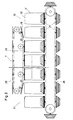
- Die Erfindung ist nachstehend anhand von zwei Anlagen zur Herstellung von Spundfässern und von Weithalsfässern aus Kunststoff näher erläutert. Es zeigt in schematischer Darstellung
- Fig. 1 einen Grundriß einer Anlage zur Herstellung von Spundfässern,
- Fig. 2 die Kühl- und Kalibrierstrecke für die Faßkörper der Anlage nach Fig. 1,
- Fig. 3 eine ausschnittsweise vergrößerte Darstellung der Kühl- und Kalibrierstrecke für die Spunddeckel der Anlage nach Fig. 1 und
- Fig. 4 einen Grundriß einer Anlage zur Herstellung von Weithalsfässern.
- Hauptbestandteile der Anlage nach den Fign. 1 bis 3 zur Herstellung von Spundfässern sind eine Maschine 1 zum Blasen von Doppelfaßkörpern 2 aus Kunststoff, eine Schneideeinrichtung 3 zum mittigen Trennen der Doppelfaßkörper 2 in zwei Faßkörper 4, eine Spritzgießmaschine 5 zur Herstellung der Spunddeckel 6 aus Kunststoff, der Blasmaschine 1 und der Spritzgießmaschine 5 nachgeordnete Kühl- und Kalibrierstrecken 7, 8 für die Faßkörper 4 und die Spunddeckel 6, eine an die Kühl- und Kalibrierstrecke 8 für die Spunddekkel 6 anschließende Bearbeitungsmaschine 9 zum maßgenauen Schneiden des unteren Deckelrandes und Abschneiden der Butzen vom Spritzen in der Spritzgießmaschine 5, zwei Schweißmaschinen 10 zum Verschweißen der Spunddeckel 6 mit den Faßkörpern 4, eine Maschine 11 zum Bearbeiten der Schweißnaht, eine Einrichtung 12 zum Erhitzen des Schweißnahtbereiches der Spundfässer 13 mittels Flamme, eine Einrichtung 14 zur Prüfung der Dichtheit der Spundfässer 13, eine Signiereinrichtung 15, ein Querförderer 16 zum Ausschleusen der fehlerhaften Spundfässer, eine Konfektioniereinrichtung 17 und eine Förderbandentnahmestation 18.
- Die in der Blasmaschine 1 aus einem Kunststoffgranulat hergestellten Doppelfaßkörper 2 werden von einem Roboter 19 zu der Schneideeinrichtung 3 transportiert, in der die Doppelfaßkörper 2 durch Herausschneiden eines Mittelringes, der die Blasöffnung des Einschießblasdornes enthält, in zwei gleiche Faßkörper 4 geteilt werden. Die Faßkörper 4 werden von dem Roboter 19 von der Schneideeinrichtung 3 zu einer Wiegeeinrichtung 20 gebracht. Faßkörper mit Übergewicht werden aussortiert und von dem Roboter 19 einem Förderband 21 übergeben, das die übergewichtigen Faßkörper zusammen mit den in der Schneideeinrichtung 3 als Abfallprodukt anfallenden Ringen einer Schneidmühle 22 zuführt, wobei das Förderband 21 als Kühlstrecke für das mit Temperaturen von 60 bis 70 C anfallende Abfallmaterial dient. Eine Absaugvorrichtung 23 fördert das in der Schneidmühle 22 produzierte Granulat in Mahlgutsilos 24. Das Mahlgut aus den Silos 24 wird mit frischem Granulat aus den Rohstoffsilos 25 vermischt, und die Granulatmischung wird der Blasmaschine 1 zugeleitet. Der Roboter 19 bringt die Faßkörper 4 mit vorschriftsmäßigem Gewicht zu der Kühl- und Kalibrierstrecke 7.
- Die Kühl- und Kalibrierstrecke 7 nach Fig. 2 weist einen unteren Endlosförderer 26 mit Kühl-und Kalibriersockeln 27 zur Aufnahme der Faßkörper 4 in Kopflage 4' und einen oberen Endlosförderer 28 mit Andrückplatten 29 zum Halten der Faßkörper 4 auf den Kalibriersockeln 27 auf, wobei die Endlosförderer 26, 28 als Kettenförderer ausgebildet sind. Der untere Endlosförderer 26 ist im Zuführbereich 30 und Entnahmebereich 31 über die Enden des oberen Endlosförderers 28 vorgezogen, so daß im Zuführbereich 30 genügend Platz für den Roboter 19 zur Verfügung steht, um einen Faßkörper 4 in Kopflage 4' auf einen Kalibriersokkel 27 aufzusetzen, bevor eine Andrückplatte 29 des oberen Endlosförderers 28 sich auf den Faßboden 32 auflegt. In gleicher Weise ist im Entnahmebereich 31 Platz für eine Entnahme- und Wendevorrichtung 33 vorhanden, um einen Faßkörper nach Durchlaufen der Kühl-und Kalibrierstrecke 7 und Freigabe des Faßkörpers durch die jeweils auf dem Faßboden 32 aufliegende Andrückplatte 29 des oberen Endlosförderers 28 von dem Kalibriersockel 27 abzuheben und den Faßkörper 4 liegend und mit in Förderrichtung weisender Längsachse an einen Querförderer 34 zu übergeben. Ein als Kettenförderer ausgebildeter Längsförderer 35 übernimmt die nunmehr quer zur Förderrichtung liegenden Faßkörper 4 von dem Querförderer 34 und transportiert diese zu zwei hintereinander angeordneten Spiegelschweißmaschinen 10.
- Die mit einer Manteltemperatur von ca. 50 - 60 C in die Kühl- und Kalibrierstrecke 7 eintretenden Faßkörper 4 werden taktweise über einen Zeitraum von ca. 30 Minuten von Haltestation zu Haltestation durch die Kühl- und Kalibrierstrecke 7 gefördert und auf Raumtemperatur abgekühlt. In den hintereinander liegenden Haltestationen werden die Faßkörper 4 mit Kühlluft angeblasen. Dabei wird der Wärmeentzug von den Faßkörpern überwiegend durch Konvektion und Wärmeableitung über die Kalibriersockel 27 und die Andrückplatten 29 aus Aluminium mit einer hohen Wärmeleitzahl bewirkt. Durch die Abkühlung der Faßkörper 4 auf den Kalibriersockeln 27 wird erreicht, daß der Durchmesser des Öffnungsrandes der die Kühl-und Kalibrierstrecke 7 verlassenden Faßkörper 4 mit dem Durchmesser des unteren Randes der in der Spritzgießmaschine 5 gespritzten Spunddeckel 6 übereinstimmt, nachdem diese die der Spritzgießmaschine 5 nachgeordnete Kühl- und Kalibrierstrecke 8 durchlaufen haben.
- Aufbau und Wirkungsweise der Kühl- und Kalibrierstrecke 8, der die in der Spritzgießmaschine 5 gespritzten Spunddeckel 6 durch einen Roboter 36 übergeben werden, sind analog dem Aufbau und der Wirkungsweise der Kühl- und Kalibrierstrecke 7 für die Faßkörper 4. Die Kühl- und Kalibrierstrecke 8 nach Fig. 3 weist einen unteren Endlosförderer 37 mit unteren Kühl- und Kalibrierplatten 38 und einen oberen Endlosförderer 39 mit oberen Kühl-und Kalibrierplatten 40 zum Einspannen der Spunddeckel 6 auf. Die Endlosförderer 37, 39 sind als Kettenförderer ausgebildet. Die Kühl- und Kalibrierplatten 38, 40 sind aus Aluminium hergestellt.
- In der an die Kühl- und Kalibrierstrecke 8 anschließenden Bearbeitungsmaschine 9 werden die vom Spritzen stammenden Butzen von den Spunddeckeln 6 und der über das Nenn-Höhenmaß der Spunddeckel vorstehende Ringabschnitt des unteren Deckelrandes der mit einem Übermaß gespritzten Deckel zur Vorbereitung einer Schweißfläche am unteren Deckelrand ohne die sich beim Spritzen der Deckel bildende Oxidhaut abgeschnitten. Butzen und Ringe werden mit einem Transportband 41 zu dem Transportband 21 überführt und von diesem zusammen mit den beim Blasen und Trennen der Doppelfaßkörper 2 anfallenden Abfallprodukten zu der Schneidmühle 22 gefördert.
- Zwei Portal-Linearroboter 42, 43 transportieren die Spunddeckel 6 von der Bearbeitungsmaschine 9 zu den beiden Spiegelschweißmaschinen 10, in denen die Spunddeckel 6 mit den aus der Kühl-und Kalibrierstrecke 7 kommenden Faßkörpern 4 genau passend verschweißt werden.
- Beim Verschweißen des unteren, oxidhautfreien Deckelrandes mit dem durch das Trennen der Doppelfaßkörper 2 in der Schneideeinrichtung 3 erhaltenen oxidhautfreien Öffnungsrand der Faßkörper bildet sich eine homogene Schweißnaht mit hoher Dauerstandfestigkeit und Spannungsrißbeständigkeit.
- Es besteht die Möglichkeit, vor den Spiegelschweißmaschinen 10 Pufferzonen für die Faßkörper 4 und die Spunddeckel 6 vorzusehen.
- Ein als Kettenförderer ausgebildeter Längsförderer 44 transportiert die Spundfässer 13 von den Spiegelschweißmaschinen 10 zu der Bearbeitungsmaschine 11, die die überstehende Schweißnaht der Spundfässer abschneidet, und von dort über die Einrichtung 12 zum Erhitzen des Schweißnahtbereiches der Spundfässer mittels einer Flamme zur Beseitigung von Schweißspannungen zu einer Wendeeinrichtung 45, die die Spundfässer in aufrechter Position an ein weiteres, längsgerichtetes Förderband 46 übergibt.
- Das Förderband 46 transportiert die Spundfässer 13 weiter zu der Prüfeinrichtung 14, in der die Fässer auf Dichtheit geprüft werden, von dort zu der Signiereinrichtung 15, in der die Fässer eine fortlaufende Produktionsnummer und ein Firmenzeichen erhalten, vorbei an dem Querförderer 16 zum Ausschleusen der fehlerhaften Fässer zu der Konfektioniereinrichtung 17, in der die Spunde mit Gewindestopfen verschlossen werden und die Fässer ggf. noch weiter kundenspezifisch ausgerüstet werden, und von dort zu der Entnahmestation 18 am Ende des Förderbandes 46.
- Die fertiggestellten Spundfässer werden vor dem Abtransport zum Abnehmer vorzugsweise in einer nicht dargestellten Palettiereinrichtung auf Paletten gestellt, die nach Bedarf in einer anschließenden, ebenfalls nicht dargestellten Stretcheinrichtung zu Einheiten von mehreren Paletten zusammengepackt werden können.
- Hauptbestandteile der Anlage nach Fig. 4 zur Herstellung von Weithalsfässern sind eine Maschine 47 zum Blasen von Doppalfaßkörpern 48 aus Kunststoff, eine Schneideeinrichtung 49 zum mittigen Trennen der Doppelfaßkörper 48 in zwei Faßkörper 50 mit jeweils einer mit Abstand unterhalb der Faßöffnung angeformten Bordur, eine Spritzgießmaschine 51 zur Herstellung der Faßdeckel 52 aus Kunststoff, der Blasmaschine 47 und der Spritzgießmaschine 51 nachgeordnete Kühl- und Kalibrierstrecken 53, 54 für die Faßkörper 50 und die Faßdeckel 52, eine Maschine 55 zum Abtrennen der Butzen von den Faßdeckeln 52, eine Maschine 56 zum Einspritzen eines Kunststoff-Dichtmaterials in die Deckel 52 und eine dieser nachgeordnete Trockeneinrichtun5 57 sowie ein Montagestand 58 zum Aufsetzen der Deckel 52 auf die Faßkörper 50 und Verschließen der Deckel mit einem Spannring. Bei der Herstellung von Weithalsfässern mit Inliner werden die Faßkörper 50 auf dem Montagestand 58 mit einem flexiblen Inliner aus einer Kunststoffolie oder einer Metall-Kunstverbundfolie ausgestattet.
- Die in der Blasmaschine 47 aus einem Kunststoffgranulat hergestellten Doppelfaßkörper 48 werden von einem Roboter 59 zu der Schneideeinrichtung 49 transportiert, in der die Doppelfaßkörper 48 in zwei gleiche Faßkörper 50 geteilt werden. Die Faßkörper 50 werden von dem Roboter 59 von der Schneideeinrichtung 49 zu einer Wiegeeinrichtung 60 gebracht. Faßkörper mit Übergewicht werden aussortiert und von dem Roboter 59 einem Förderband 61 übergeben, das die übergewichtigen Faßkörper zusammen mit den in der Schneideeinrichtung 49 anfallenden Kunststoffringen einer Schneidmühle 62 zuführt. Eine Absaugvorrichtung 63 fördert das in der Schneidmühle 62 produzierte Granulat in Mahlgutsilos 64 zur Wiederverarbeitung in einer Mischung mit frischem Granulat. Der Roboter 59 bringt die Faßkörper 50 mit vorschriftsmäßigem Gewicht zu der Kühl- und Kalibrierstrecke 53, deren Aufbau und Wirkungsweise der Konstruktion und der Wirkungsweise der Kühl- und Kalibrierstrecke 7 der vorbeschriebenen Anlage zur Herstellung von Spundfässern entsprechen.
- Nach Durchlaufen der Kühl- und Kalibrierstrekke 53 werden die Faßkörper 50 von einer Entnahme- und Wendevorrichtung 65 an ein Transportband 66 übergeben, das die Faßkörper zu dem Montagestand 58 bringt.
- Die die Spritzgießmaschine 51 verlassenden Deckel 52 werden von einem Roboter 67 übernommen und in die Kühl- und Kalibrierstrecke 54 eingeschleust, die der Kühl- und Kalibrierstrecke 8 der vorbeschriebenen Anlage zur Herstellung von Spundfässern entspricht. In der an die Kühl- und Kalibrierstrecke 54 anschließenden Bearbeitungsmaschine 55 werden die an die Deckel 52 angespritzten Butzen abgeschnitten, die zusammen mit dem in der Schneideeinrichtung 49 produzierten Abfall und den Ausschußfässern von der Blasmaschine 47 in die Schneidmühle 62 transportiert werden. Von der Bearbeitungsmaschine 55 werden die Faßdeckel 52 in die Spritzmaschine 56 überführt, mit der eine Zweikomponenten-Kunststoffdichtungsmasse in die Deckel eingespritzt wird. Von der Spritzmaschine 56 werden die Deckel mit einem Förderband 68 in die Trockeneinrichtung 57 transportiert, in der die auf dem Transportweg zwischen Spritzmaschine und Trockeneinrichtung eingeleitete Reaktion zwischen der Kunststoffdichtungsmasse und einem beigemischten Härter abgeschlossen wird. Auf dem Montagestand 58 werden die der Trockeneinrichtung 57 entnommenen Faßdeckel 52 auf die Faßkörper 50 - ggf. nach Einbringen eines Inliners - aufgesetzt, und die Faßdeckel werden mit einem Spannring verschlossen.
- Die fertiggestellten Weithalsfässer 69 werden nach dem Signieren palettiert, und die Paletten mit den Fässern können nach Bedarf zu Einheiten von mehreren Paletten zusammengepackt werden.
Claims (13)
Applications Claiming Priority (2)
| Application Number | Priority Date | Filing Date | Title |
|---|---|---|---|
| DE4022926A DE4022926C2 (de) | 1990-07-19 | 1990-07-19 | Verfahren zur Herstellung von Fässern aus thermoplastischem Kunststoff und Anlage zur Durchführung des Verfahrens |
| DE4022926 | 1990-07-19 |
Publications (2)
| Publication Number | Publication Date |
|---|---|
| EP0467162A1 true EP0467162A1 (de) | 1992-01-22 |
| EP0467162B1 EP0467162B1 (de) | 1993-09-29 |
Family
ID=6410567
Family Applications (1)
| Application Number | Title | Priority Date | Filing Date |
|---|---|---|---|
| EP91111114A Expired - Lifetime EP0467162B1 (de) | 1990-07-19 | 1991-07-04 | Verfahren zur Herstellung von Spund- und Weithalsfässern |
Country Status (19)
| Country | Link |
|---|---|
| US (1) | US5205885A (de) |
| EP (1) | EP0467162B1 (de) |
| JP (1) | JP2593371B2 (de) |
| CN (1) | CN1106738A (de) |
| AT (1) | ATE95133T1 (de) |
| BR (1) | BR9103086A (de) |
| CA (1) | CA2047385C (de) |
| CZ (1) | CZ280641B6 (de) |
| DE (2) | DE4022926C2 (de) |
| DK (1) | DK0467162T3 (de) |
| ES (1) | ES2044658T3 (de) |
| IE (1) | IE66729B1 (de) |
| IL (1) | IL98792A (de) |
| NO (1) | NO912788L (de) |
| PL (2) | PL166956B1 (de) |
| PT (1) | PT98368B (de) |
| RU (1) | RU2040401C1 (de) |
| YU (1) | YU48055B (de) |
| ZA (1) | ZA914999B (de) |
Cited By (1)
| Publication number | Priority date | Publication date | Assignee | Title |
|---|---|---|---|---|
| DE102008035945A1 (de) * | 2008-07-31 | 2010-02-04 | Bayerische Motoren Werke Aktiengesellschaft | Verfahren zur Herstellung von Fahrzeugteilen aus Kunststoff |
Families Citing this family (8)
| Publication number | Priority date | Publication date | Assignee | Title |
|---|---|---|---|---|
| DE4437748C2 (de) * | 1994-09-20 | 1996-07-04 | Schuetz Werke Gmbh Co Kg | Verfahren zum Rekonditionieren von genormten Spundfässern aus Kunststoff |
| CN100377860C (zh) * | 2003-07-25 | 2008-04-02 | 李卫东 | 塑料挤出全自动吹瓶机 |
| CN101264661B (zh) * | 2008-04-03 | 2010-09-08 | 李志彬 | 吹瓶机 |
| NL2007390C2 (nl) | 2011-09-12 | 2013-03-13 | Polymac B V | Werkwijze en systeem voor het vervaardigen van een spuitgietproduct, alsmede etiketoverbrenginrichting. |
| US10179435B2 (en) | 2012-07-10 | 2019-01-15 | U.S. Farathane Corporation | Roof ditch molding assembly and process with heated air assist |
| US10071522B2 (en) * | 2012-07-10 | 2018-09-11 | U.S. Farathane Corporation | Roof ditch molding process incorporating conformed shaping features in a molding fixture |
| CN102735173B (zh) * | 2012-07-11 | 2014-12-10 | 江苏万乐复合材料有限公司 | 内粘膜塑料编织袋内粘机宽度检测系统 |
| CN107244059B (zh) * | 2017-08-07 | 2019-04-16 | 安庆市阳光雨露食品有限责任公司 | 一种塑料瓶自动加工设备 |
Citations (7)
| Publication number | Priority date | Publication date | Assignee | Title |
|---|---|---|---|---|
| BE643809A (de) * | 1963-02-16 | 1964-05-29 | ||
| US3432586A (en) * | 1966-07-29 | 1969-03-11 | American Can Co | Process for forming plastic containers |
| DE1914714A1 (de) * | 1969-03-22 | 1970-10-15 | Goetzewerke | Verfahren und Vorrichtung zum Herstellen von Hohlkoerpern aus vulkanisierbaren Werkstoffen,insbesondere von zylindrischen Gleitlagern |
| EP0162117A1 (de) * | 1984-02-07 | 1985-11-27 | Marius A.J. Verlinden | Verfahren zur Herstellung eines Bierfasses |
| EP0302266A2 (de) * | 1987-08-06 | 1989-02-08 | Sotralentz S.A. | Verfahren und Anlage zur Herstellung eines Spundfasses aus thermoplastischem Kunststoff und nach dem Verfahren hergestelltes Spundfass |
| EP0342313A2 (de) * | 1988-05-19 | 1989-11-23 | Karl Heess Gmbh & Co. Maschinenbau | Verfahren und Vorrichtung zur kontrollierten Beeinflussung des Innen-und/oder Aussendurchmessers beim Abkühlvorgang von zu härtenden Werkstücken |
| DE3917524C1 (de) * | 1989-05-30 | 1990-09-06 | Schuetz-Werke Gmbh & Co Kg, 5418 Selters, De |
Family Cites Families (13)
| Publication number | Priority date | Publication date | Assignee | Title |
|---|---|---|---|---|
| US3196593A (en) * | 1960-11-10 | 1965-07-27 | Lever Brothers Ltd | Manufacture and filling of containers |
| US3457590A (en) * | 1965-10-20 | 1969-07-29 | Continental Can Co | Tandem blow molding apparatus |
| US3454690A (en) * | 1966-05-16 | 1969-07-08 | Haskon Inc | Plastic container construction |
| US3862698A (en) * | 1973-06-01 | 1975-01-28 | Ethyl Dev Corp | Blow molded article of manufacture |
| DE2544491C2 (de) * | 1975-10-04 | 1983-12-22 | Mauser KG, 5040 Brühl | Deckelfaß |
| FR2391056A1 (fr) * | 1977-05-18 | 1978-12-15 | Naphtachimie Sa | Procede et dispositif de fabrication par moulage de recipients et de capsules en matiere thermoplastique |
| US4201306A (en) * | 1978-10-27 | 1980-05-06 | Greif Bros. Corporation | Variable capacity all-plastic drum |
| BE887814A (fr) * | 1981-03-06 | 1981-07-01 | Verlinden Marius A J | Procede de fabrication d'un fut a pression et fut a pression ainsi fabrique |
| US4412628A (en) * | 1981-04-17 | 1983-11-01 | Born Free Plastics, Inc. | Thermoplastic drum apparatus |
| US4548668A (en) * | 1983-01-10 | 1985-10-22 | Continental Can Company, Inc. | Combination machine for assembling container components |
| DE8631318U1 (de) * | 1986-11-22 | 1987-01-15 | Schütz-Werke GmbH & Co KG, 5418 Selters | Spundfaß |
| DD270494A5 (de) * | 1987-02-12 | 1989-08-02 | ���������`��������������@����@�K@��Kk�� | Vorrichtung zum herstellen eines kunststoff-hohlkoerpers mit durch blasen geformtem koerperteil |
| DE3737884A1 (de) * | 1987-11-07 | 1989-06-01 | Sotralentz Sa | Fassgebinde mit fasskoerper und deckel aus kunststoff sowie spannverschluss |
-
1990
- 1990-07-19 DE DE4022926A patent/DE4022926C2/de not_active Expired - Fee Related
-
1991
- 1991-06-28 ZA ZA914999A patent/ZA914999B/xx unknown
- 1991-07-04 EP EP91111114A patent/EP0467162B1/de not_active Expired - Lifetime
- 1991-07-04 DE DE91111114T patent/DE59100425D1/de not_active Expired - Fee Related
- 1991-07-04 AT AT91111114T patent/ATE95133T1/de not_active IP Right Cessation
- 1991-07-04 DK DK91111114.4T patent/DK0467162T3/da active
- 1991-07-04 ES ES91111114T patent/ES2044658T3/es not_active Expired - Lifetime
- 1991-07-11 IL IL9879291A patent/IL98792A/en unknown
- 1991-07-12 YU YU123491A patent/YU48055B/sh unknown
- 1991-07-16 NO NO91912788A patent/NO912788L/no unknown
- 1991-07-16 PL PL91291095A patent/PL166956B1/pl unknown
- 1991-07-16 PL PL91305363A patent/PL167623B1/pl unknown
- 1991-07-17 CZ CS912221A patent/CZ280641B6/cs unknown
- 1991-07-18 IE IE252091A patent/IE66729B1/en not_active IP Right Cessation
- 1991-07-18 RU SU915001067A patent/RU2040401C1/ru active
- 1991-07-18 BR BR919103086A patent/BR9103086A/pt not_active Application Discontinuation
- 1991-07-18 CA CA002047385A patent/CA2047385C/en not_active Expired - Fee Related
- 1991-07-18 PT PT98368A patent/PT98368B/pt not_active IP Right Cessation
- 1991-07-19 JP JP3179303A patent/JP2593371B2/ja not_active Expired - Lifetime
- 1991-07-19 US US07/732,758 patent/US5205885A/en not_active Expired - Lifetime
-
1994
- 1994-10-26 CN CN94116040A patent/CN1106738A/zh active Pending
Patent Citations (7)
| Publication number | Priority date | Publication date | Assignee | Title |
|---|---|---|---|---|
| BE643809A (de) * | 1963-02-16 | 1964-05-29 | ||
| US3432586A (en) * | 1966-07-29 | 1969-03-11 | American Can Co | Process for forming plastic containers |
| DE1914714A1 (de) * | 1969-03-22 | 1970-10-15 | Goetzewerke | Verfahren und Vorrichtung zum Herstellen von Hohlkoerpern aus vulkanisierbaren Werkstoffen,insbesondere von zylindrischen Gleitlagern |
| EP0162117A1 (de) * | 1984-02-07 | 1985-11-27 | Marius A.J. Verlinden | Verfahren zur Herstellung eines Bierfasses |
| EP0302266A2 (de) * | 1987-08-06 | 1989-02-08 | Sotralentz S.A. | Verfahren und Anlage zur Herstellung eines Spundfasses aus thermoplastischem Kunststoff und nach dem Verfahren hergestelltes Spundfass |
| EP0342313A2 (de) * | 1988-05-19 | 1989-11-23 | Karl Heess Gmbh & Co. Maschinenbau | Verfahren und Vorrichtung zur kontrollierten Beeinflussung des Innen-und/oder Aussendurchmessers beim Abkühlvorgang von zu härtenden Werkstücken |
| DE3917524C1 (de) * | 1989-05-30 | 1990-09-06 | Schuetz-Werke Gmbh & Co Kg, 5418 Selters, De |
Non-Patent Citations (1)
| Title |
|---|
| PATENT ABSTRACTS OF JAPAN, Band 14, Nr. 315 (M-995)[4258], 6. Juli 1990; & JP-A-2 106 325 (TAKIRON CO., LTD) 18-04-1990 * |
Cited By (1)
| Publication number | Priority date | Publication date | Assignee | Title |
|---|---|---|---|---|
| DE102008035945A1 (de) * | 2008-07-31 | 2010-02-04 | Bayerische Motoren Werke Aktiengesellschaft | Verfahren zur Herstellung von Fahrzeugteilen aus Kunststoff |
Also Published As
| Publication number | Publication date |
|---|---|
| CS222191A3 (en) | 1992-02-19 |
| CA2047385C (en) | 1994-03-22 |
| IL98792A0 (en) | 1992-07-15 |
| YU123491A (sh) | 1996-01-08 |
| RU2040401C1 (ru) | 1995-07-25 |
| PL166956B1 (pl) | 1995-07-31 |
| ES2044658T3 (es) | 1994-01-01 |
| ATE95133T1 (de) | 1993-10-15 |
| CA2047385A1 (en) | 1992-01-20 |
| BR9103086A (pt) | 1992-02-11 |
| US5205885A (en) | 1993-04-27 |
| IE66729B1 (en) | 1996-01-24 |
| CN1106738A (zh) | 1995-08-16 |
| DE4022926A1 (de) | 1992-01-23 |
| DE4022926C2 (de) | 1994-08-04 |
| JP2593371B2 (ja) | 1997-03-26 |
| NO912788D0 (no) | 1991-07-16 |
| JPH04226734A (ja) | 1992-08-17 |
| CZ280641B6 (cs) | 1996-03-13 |
| YU48055B (sh) | 1996-10-18 |
| EP0467162B1 (de) | 1993-09-29 |
| IL98792A (en) | 1994-11-11 |
| DE59100425D1 (de) | 1993-11-04 |
| PT98368A (pt) | 1993-09-30 |
| PT98368B (pt) | 1999-01-29 |
| IE912520A1 (en) | 1992-01-29 |
| PL167623B1 (pl) | 1995-09-30 |
| ZA914999B (en) | 1992-04-29 |
| DK0467162T3 (da) | 1994-01-03 |
| NO912788L (no) | 1992-01-20 |
| PL291095A1 (en) | 1992-02-10 |
Similar Documents
| Publication | Publication Date | Title |
|---|---|---|
| DE69801174T2 (de) | Verfahren und Vorrichtung zur Herstellung von Vorformen mit kristallisierten Hälsen | |
| DE60314777T2 (de) | Doppelfolien thermoformung von kraftstofftanks | |
| EP0467162B1 (de) | Verfahren zur Herstellung von Spund- und Weithalsfässern | |
| DE69423025T2 (de) | Prüfung und Sortierung von Behältern | |
| DE69712929T2 (de) | Vorrichtung zum Blasfromen | |
| US4507258A (en) | Method for injection molding a composite parison | |
| DE202009019170U1 (de) | Vorrichtung zum Herstellen von Kunstoffflaschen | |
| EP1189740A1 (de) | Vorrichtung zur blasformung von behältern | |
| DE69622306T2 (de) | Mehrschichtiger Kunststoffgegenstand und Verfahren zu seiner Herstellung | |
| WO2013107657A1 (de) | Verfahren und vorrichtung zur blasformung von behältern | |
| DE69705546T2 (de) | Verfahren zum herstellen und handhaben von teilen für einen verpackungsbehälter | |
| EP2347882A2 (de) | Vorrichtung und Verfahren zum Herstellen von Behältern aus Kunststoff | |
| EP0323548B1 (de) | Verfahren zur Herstellung eines Kunststoffbehälters durch Blasformen und Vorrichtung für die Durchführung des Verfahrens | |
| DE1950212A1 (de) | Verfahren und Vorrichtung zur Herstellung von Hohlkoerpern aus Thermoplasten durch Spritzgiessblasformen | |
| CN1058169A (zh) | 制造塞桶和宽颈桶的方法 | |
| DE102020130007A1 (de) | Verfahren zum Herstellen von Kunststoffflaschen und Streckblasmaschine | |
| DE202020103757U1 (de) | Behälterteller | |
| DE1479116A1 (de) | Blasverformung | |
| DE1704331A1 (de) | Verfahren und Einrichtung zur Herstellung von Hohlkoerpern,z.B.von Flaschen aus Kunststoff und nach diesem Verfahren hergestellter Flaschenbehaelter | |
| DE60004690T2 (de) | Methode zum blasformen eines kunststoff-containers | |
| DE10208053B3 (de) | Slush-Moulding-Anlage zur Herstellung einer Kunststoffhaut | |
| DE102010049505A1 (de) | Verfahren und Vorrichtung zur Herstellung von Behältern sowie blasgeformter Behälter | |
| DE2239265A1 (de) | Verfahren zur herstellung von mehrschichtigen gegenstaenden | |
| WO2007065392A2 (de) | Verfahren und vorrichtung zur blasformung von behältern mit anschlagelementen zur positionsfestlegung des vorformlings | |
| CH468282A (de) | Verfahren und Einrichtung zur Herstellung, zum Füllen und Schliessen von Flaschen aus Kunststoff und nach diesem Verfahren hergestellte Flasche |
Legal Events
| Date | Code | Title | Description |
|---|---|---|---|
| PUAI | Public reference made under article 153(3) epc to a published international application that has entered the european phase |
Free format text: ORIGINAL CODE: 0009012 |
|
| AK | Designated contracting states |
Kind code of ref document: A1 Designated state(s): AT BE CH DE DK ES FR GB GR IT LI LU NL SE |
|
| 17P | Request for examination filed |
Effective date: 19920702 |
|
| 17Q | First examination report despatched |
Effective date: 19930204 |
|
| GRAA | (expected) grant |
Free format text: ORIGINAL CODE: 0009210 |
|
| AK | Designated contracting states |
Kind code of ref document: B1 Designated state(s): AT BE CH DE DK ES FR GB GR IT LI LU NL SE |
|
| REF | Corresponds to: |
Ref document number: 95133 Country of ref document: AT Date of ref document: 19931015 Kind code of ref document: T |
|
| REF | Corresponds to: |
Ref document number: 59100425 Country of ref document: DE Date of ref document: 19931104 |
|
| GBT | Gb: translation of ep patent filed (gb section 77(6)(a)/1977) |
Effective date: 19931015 |
|
| ET | Fr: translation filed | ||
| ITF | It: translation for a ep patent filed | ||
| REG | Reference to a national code |
Ref country code: GR Ref legal event code: FG4A Free format text: 3009487 |
|
| REG | Reference to a national code |
Ref country code: ES Ref legal event code: FG2A Ref document number: 2044658 Country of ref document: ES Kind code of ref document: T3 |
|
| REG | Reference to a national code |
Ref country code: DK Ref legal event code: T3 |
|
| PLBE | No opposition filed within time limit |
Free format text: ORIGINAL CODE: 0009261 |
|
| STAA | Information on the status of an ep patent application or granted ep patent |
Free format text: STATUS: NO OPPOSITION FILED WITHIN TIME LIMIT |
|
| 26N | No opposition filed | ||
| EAL | Se: european patent in force in sweden |
Ref document number: 91111114.4 |
|
| PGFP | Annual fee paid to national office [announced via postgrant information from national office to epo] |
Ref country code: FR Payment date: 19970514 Year of fee payment: 7 |
|
| PGFP | Annual fee paid to national office [announced via postgrant information from national office to epo] |
Ref country code: GB Payment date: 19970701 Year of fee payment: 7 |
|
| PGFP | Annual fee paid to national office [announced via postgrant information from national office to epo] |
Ref country code: AT Payment date: 19970702 Year of fee payment: 7 |
|
| PGFP | Annual fee paid to national office [announced via postgrant information from national office to epo] |
Ref country code: GR Payment date: 19970709 Year of fee payment: 7 |
|
| PGFP | Annual fee paid to national office [announced via postgrant information from national office to epo] |
Ref country code: LU Payment date: 19970710 Year of fee payment: 7 |
|
| PGFP | Annual fee paid to national office [announced via postgrant information from national office to epo] |
Ref country code: ES Payment date: 19970711 Year of fee payment: 7 |
|
| PGFP | Annual fee paid to national office [announced via postgrant information from national office to epo] |
Ref country code: DK Payment date: 19970714 Year of fee payment: 7 |
|
| PGFP | Annual fee paid to national office [announced via postgrant information from national office to epo] |
Ref country code: SE Payment date: 19970723 Year of fee payment: 7 |
|
| PGFP | Annual fee paid to national office [announced via postgrant information from national office to epo] |
Ref country code: NL Payment date: 19970731 Year of fee payment: 7 Ref country code: BE Payment date: 19970731 Year of fee payment: 7 |
|
| PGFP | Annual fee paid to national office [announced via postgrant information from national office to epo] |
Ref country code: CH Payment date: 19971030 Year of fee payment: 7 |
|
| PG25 | Lapsed in a contracting state [announced via postgrant information from national office to epo] |
Ref country code: LU Free format text: LAPSE BECAUSE OF NON-PAYMENT OF DUE FEES Effective date: 19980704 Ref country code: GB Free format text: LAPSE BECAUSE OF NON-PAYMENT OF DUE FEES Effective date: 19980704 Ref country code: AT Free format text: LAPSE BECAUSE OF NON-PAYMENT OF DUE FEES Effective date: 19980704 |
|
| PG25 | Lapsed in a contracting state [announced via postgrant information from national office to epo] |
Ref country code: SE Free format text: LAPSE BECAUSE OF NON-PAYMENT OF DUE FEES Effective date: 19980705 |
|
| PG25 | Lapsed in a contracting state [announced via postgrant information from national office to epo] |
Ref country code: ES Free format text: LAPSE BECAUSE OF THE APPLICANT RENOUNCES Effective date: 19980706 |
|
| PG25 | Lapsed in a contracting state [announced via postgrant information from national office to epo] |
Ref country code: LI Free format text: LAPSE BECAUSE OF NON-PAYMENT OF DUE FEES Effective date: 19980731 Ref country code: GR Free format text: LAPSE BECAUSE OF NON-PAYMENT OF DUE FEES Effective date: 19980731 Ref country code: DK Free format text: LAPSE BECAUSE OF NON-PAYMENT OF DUE FEES Effective date: 19980731 Ref country code: CH Free format text: LAPSE BECAUSE OF NON-PAYMENT OF DUE FEES Effective date: 19980731 Ref country code: BE Free format text: LAPSE BECAUSE OF NON-PAYMENT OF DUE FEES Effective date: 19980731 |
|
| BERE | Be: lapsed |
Owner name: SCHUTZ-WERKE G.M.B.H. & CO. K.G. Effective date: 19980731 |
|
| PG25 | Lapsed in a contracting state [announced via postgrant information from national office to epo] |
Ref country code: NL Free format text: LAPSE BECAUSE OF NON-PAYMENT OF DUE FEES Effective date: 19990201 |
|
| GBPC | Gb: european patent ceased through non-payment of renewal fee |
Effective date: 19980704 |
|
| REG | Reference to a national code |
Ref country code: CH Ref legal event code: PL |
|
| EUG | Se: european patent has lapsed |
Ref document number: 91111114.4 |
|
| PG25 | Lapsed in a contracting state [announced via postgrant information from national office to epo] |
Ref country code: FR Free format text: LAPSE BECAUSE OF NON-PAYMENT OF DUE FEES Effective date: 19990331 |
|
| NLV4 | Nl: lapsed or anulled due to non-payment of the annual fee |
Effective date: 19990201 |
|
| REG | Reference to a national code |
Ref country code: FR Ref legal event code: ST |
|
| REG | Reference to a national code |
Ref country code: DK Ref legal event code: EBP |
|
| REG | Reference to a national code |
Ref country code: ES Ref legal event code: FD2A Effective date: 20001102 |
|
| PGFP | Annual fee paid to national office [announced via postgrant information from national office to epo] |
Ref country code: DE Payment date: 20040924 Year of fee payment: 14 |
|
| PG25 | Lapsed in a contracting state [announced via postgrant information from national office to epo] |
Ref country code: IT Free format text: LAPSE BECAUSE OF NON-PAYMENT OF DUE FEES;WARNING: LAPSES OF ITALIAN PATENTS WITH EFFECTIVE DATE BEFORE 2007 MAY HAVE OCCURRED AT ANY TIME BEFORE 2007. THE CORRECT EFFECTIVE DATE MAY BE DIFFERENT FROM THE ONE RECORDED. Effective date: 20050704 |
|
| PG25 | Lapsed in a contracting state [announced via postgrant information from national office to epo] |
Ref country code: DE Free format text: LAPSE BECAUSE OF NON-PAYMENT OF DUE FEES Effective date: 20060201 |