EP0467505A2 - Verfahren und Vorrichtung zur Behandlung eines Fluides - Google Patents
Verfahren und Vorrichtung zur Behandlung eines Fluides Download PDFInfo
- Publication number
- EP0467505A2 EP0467505A2 EP91303873A EP91303873A EP0467505A2 EP 0467505 A2 EP0467505 A2 EP 0467505A2 EP 91303873 A EP91303873 A EP 91303873A EP 91303873 A EP91303873 A EP 91303873A EP 0467505 A2 EP0467505 A2 EP 0467505A2
- Authority
- EP
- European Patent Office
- Prior art keywords
- electrodes
- electrically conductive
- electrical insulator
- fluid
- treating
- Prior art date
- Legal status (The legal status is an assumption and is not a legal conclusion. Google has not performed a legal analysis and makes no representation as to the accuracy of the status listed.)
- Granted
Links
Images


Classifications
-
- C—CHEMISTRY; METALLURGY
- C02—TREATMENT OF WATER, WASTE WATER, SEWAGE, OR SLUDGE
- C02F—TREATMENT OF WATER, WASTE WATER, SEWAGE, OR SLUDGE
- C02F1/00—Treatment of water, waste water, or sewage
- C02F1/46—Treatment of water, waste water, or sewage by electrochemical methods
-
- C—CHEMISTRY; METALLURGY
- C02—TREATMENT OF WATER, WASTE WATER, SEWAGE, OR SLUDGE
- C02F—TREATMENT OF WATER, WASTE WATER, SEWAGE, OR SLUDGE
- C02F1/00—Treatment of water, waste water, or sewage
- C02F1/46—Treatment of water, waste water, or sewage by electrochemical methods
- C02F1/4602—Treatment of water, waste water, or sewage by electrochemical methods for prevention or elimination of deposits
-
- C—CHEMISTRY; METALLURGY
- C02—TREATMENT OF WATER, WASTE WATER, SEWAGE, OR SLUDGE
- C02F—TREATMENT OF WATER, WASTE WATER, SEWAGE, OR SLUDGE
- C02F1/00—Treatment of water, waste water, or sewage
- C02F1/46—Treatment of water, waste water, or sewage by electrochemical methods
- C02F1/461—Treatment of water, waste water, or sewage by electrochemical methods by electrolysis
- C02F1/46104—Devices therefor; Their operating or servicing
- C02F1/46176—Galvanic cells
Definitions
- the present invention relates to a method and apparatus for treating electrically conductive fluid, that is fluid having some electroconductive capability. More particularly, the present invention relates to a method and apparatus for ionizing water having a high mineral content to prevent the precipitation of solids from the water which would tend to form a scale on the inner surface of piping through which the water flows, and to aid in the removal of a previously formed scale.
- a scale mainly consisting of ferric oxide is deposited on the inner surface of the pipes thereby reducing the inner diameter of the pipes resulting in a reduced flow rate and water pressure.
- the use of ionized water to remove such a scale is well known to those of ordinary skill in the art.
- ionized water flows through piping having an oxide scale deposited on the inner surface thereof, the oxide scale is converted into a soft hydroxide (ferric hydroxide) which can be gradually removed.
- U.S. Patent No. 4,902,391 discloses a method and apparatus developed by the present inventor for ionizing, with great efficiency, fluids having a high dissolved solid content for the purpose of eliminating the problems caused by the deposition of substances such as ferric particles on the inner surface of fluid piping.
- two electrodes of electrically conductive materials having different electrochemical potentials e.g. aluminum and carbon electrodes, are used to provide a voltaic cell structure which employs fluid to be treated as the electrolyte of the cell, whereby the fluid is ionized owing to the electric potential of the electrodes.
- the present inventor carried out tests, described below, to illustrate that when electric current flow through the fluid and between the electrodes is reduced, there is an improvement in the ability of the device to prevent the precipitation of solids (Ca, Mg and Si) dissolved in the fluid and thus prevent the formation of a scale, particularly a silica scale which is the most difficult type of scale to prevent.
- An object of the present invention is to provide a method and apparatus in which relatively little current is generated during the ionization of electrically conductive fluid between electrodes having different electrochemical potentials, whereby the precipitation of dissolved solids in even fluid having a high dissolved solid content level and high electroconductivity level can be prevented.
- Another object of the present invention is to provide a method and apparatus for treating fluid in which very little electric current is generated through the fluid to be treated between electrodes having different electrochemical potentials even when such electrodes cannot be spaced very far apart from one another, whereby any physical restraints imposed by a system in which the apparatus is to be employed do not diminish the effectiveness of the present invention in preventing the formation of a scale on the pipes of a system and the removal of such a previously deposited scale.
- the invention provides an apparatus for treating electrically conductive fluid, said apparatus comprising:
- the invention also provides a method of treating electrically conductive fluid, said method comprising:
- an electrical insulator disposed between electrically isolated positive and negative electrodes having different electrochemical potentials.
- the electrical insulator extends across any shortest direct path between the spaced apart electrically conductive material of the electrodes.
- current flow in a body of fluid to be treated between the electrodes is inhibited because the electroconductive connection between the electrodes is established only through the body of fluid along a path that extends around the electrical insulator so as to be longer than any shortest direct path between the electrodes.
- the electrical insulator increases the path of resistance through the fluid between the electrodes by being interposed directly between the positive and negative electrodes, whereby such an increase in the resistive path restricts the current flow during ionization of the fluid.
- the provision of the electrical insulator can increase the length of the resistive path between the electrodes and through the fluid such that the fluid can be effectively ionized with little current flow therethrough.
- reference numeral 1 is used to designate a positive electrode of electrically conductive material while reference numeral 2 designates a negative electrode of electrically conductive material that is spaced apart and electrically isolated from the electrically conductive material of the positive electrode 1.
- the electrically conductive materials of the positive 1 and negative 2 electrodes have different electrochemical potentials so that when a body of electrically conductive fluid to be treated flows in the direction of the arrows between the electrodes 1, 2, an electroconductive connection that develops an electroconductive potential between the electrodes is only established through the body of fluid whereby the fluid is ionized.
- Reference numeral 3 designates an electrical insulator disposed between the positive 1 and negative 2 electrodes.
- the purpose of the electrical insulator 3 is to create a relatively long resistive path through the body of fluid between the electrodes 1 and 2 which inhibits current flow through the body of fluid.
- the tubular electrical insulator 3 is interposed between a rod-shaped positive electrode 1 and a tubular electrode 2.
- the electrical insulator 3 extends across any shortest direct path between the electrodes 1 and 2, i.e. any path extending radially from the rod-shaped positive electrode 1 to the tubular negative electrode 2.
- an electroconductive connection between the electrodes 1, 2 is established through the body of fluid along a path that extends around the ends of the electrical insulator 3.
- the positive electrode 1, the negative electrode 2, and the electrical insulator 3 all have substantially the same length.
- electrical insulator 3 terminates at the respective ends of the positive electrode 1 and negative electrode 2, a relatively short resistive path is provided between the electrodes and so, the effect of the electrical insulator 3 is limited. Although this apparatus does provide only a slight improvement when incorporated into small systems as compared to similar apparatus in which the electrical insulator 3 is not employed, it was found to be rather effective for relatively large systems.
- the electrical insulator 3 extends longitudinally beyond the respective ends of the positive 1 and negative 2 electrodes. Therefore, current flow between the electrodes must occur through the body of fluid along a path of resistance that extends around the longitudinally extending ends of the electrical insulator 3.
- the resistance is increased by approximately twice the difference between the length of the electrical insulator 3 and the length of the positive electrode 1 (or the negative electrode 2 of substantially equal length).
- the electric current flow between the electrodes 1, 2 is reduced compared to the apparatus shown in Figure 1, the voltage potential is not reduced. When such an apparatus was employed in small units, excellent results were achieved with water having an electroconductivity level of 2,720 aS/cm.
- the positive electrode 1 is tubular, and the electrical insulator 3 is radially interposed between and spaced from the radially innermost positive electrode 1 and the radially outermost tubular electrode 2.
- the advantages of employing a tubular positive electrode 1, as compared to the rod-shaped positive electrode of the embodiment shown in Figures 1 and 2, are that the tubular electrode 1 offers less resistance to fluid flow and presents an increased surface area (inner and outer surfaces) over which the fluid can flow.
- the embodiment of Fig. 3 can be used having smaller components than if the embodiment shown in Figures 1 and 2 were to be used.
- the electrical insulator 3 is spaced radially inwardly from the negative electrode 2, forming the radially outermost electrode, and is disposed around and in contact with the positive electrode 1 which forms the radially innermost electrode.
- the positive electrode 1, the negative electrode 2 and the electrical insulator 3 have been described as having a tubular (circular) or polygonal (round) cross section. This is because such features particularly lend themselves to use in fluid piping and fluid containers which mostly have circular cross- sectional components.
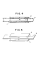
- the present invention also contemplates the use of plate electrodes as shown in the embodiment of Figure 5.
- the positive electrode 1, the negative electrode 2 and the electrical insulator 3 are each a respective flat plate.
- the electrical insulator 3 is disposed between the positive 1 and negative 2 electrodes and extends across any shortest direct path therebetween (in this case any path extending perpendicular to and between the flat plate electrodes 1, 2).
- Such flat elements can be installed into a pipe having a square or rectangular cross section and provided with appropriate fittings at each end as attaching means for securing the pipe (apparatus) in-line to standard circular cross-sectional piping of a fluid system.
- one of the positive and negative electrodes (the negative electrode 2 in Figure 6 and the positive electrode 1 in Figure 7) has substantially the same length as the electrical insulator 3 while the other of the electrodes (positive electrode 1 in Figure 6 and negative electrode 2 in Figure 7) is shorter than the electrical insulator 3 and said one of the electrodes.
- FIG 8 A practical application of the present invention is illustrated in Figure 8.
- the apparatus of Figure 8 includes a pipe 4 having flanges at the ends thereof which serve as attaching means for securing the apparatus in-line with piping of a fluid system.
- an inner lining 5 of an electrically insulative material is provided between the pipe 1 and the outer surface of negative electrode 2.
- Such an inner lining of electrically insulative material is necessary to prevent electrical contact between the pipe 4 and the negative electrode 2 which would tend to give rise to electrolysis and corrosion.
- the positive electrode 1, the electrical insulator 3 and the negative electrode 2 are supported in a concentric relation by at least one electrically insulative supporting member 6.
- Each electrically insulative supporting member 6 extends diametrically of the pipe 4 and supports the electrode 1 and the electrical insulator 3 within the pipe 4 without providing an electroconductive path between the electrodes 1, 2.
- the electrical insulator 3 extends nearly the entire length of the pipe 4, beyond the respective ends of the electrodes 1, 2.
- the pipe 4 can also be fabricated from PVC, in which case the inner lining 5 of electrically insulative material is not necessary.
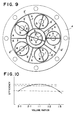
- the constituent elements of the present invention may be arranged in parallel, as shown in the apparatus of Figure 9 in which six individual units of constituent elements are integrated.
- the outer five radially spaced units have a common negative electrode formed of a first tubular portion 2' of electrical conductive material and a plurality of flat plates 7 of electrically conductive material extending from the first tubular portion 2'.
- the plurality of flat plates 7 extend radially inwardly of the first tubular portion 2' from locations spaced along an inner surface thereof so as to define a plurality of radial sectors within the tubular portion 2'.
- a respective tube 3' of electrically insulative material is disposed in each of the sectors.
- the positive electrode includes a respective rod 1' of electrically conductive material disposed within each tube 3' of electrically insulative material. Supporting members 6 of electrically insulative material are connected between each respective rod 1' and the respective tube 3' so as to support each rod 1' within a respective tube 3'.
- the centralmost unit includes a second tubular portion 2" of the negative electrode that is generally centrally located within the first tubular portion 2'.
- the flat plates 7 of the negative electrode extend radially outwardly from the second tubular portion 2" to the first tubular portion 2'.
- a central tube 3" of electrically insulative material is spaced radially inwardly of the second tubular portion 2" of the negative electrode.
- the positive electrode also includes a rod 1" of electrically conductive material supported by the at least one supporting member 6 within the central tube 3" of the electrical insulator.
- Other parallel arrangements of multiple units of the type shown in Figure 9 can of course be provided.
- the positive electrode 1 has been shown as a radially innermost electrode while the negative electrode 2 has been shown as the radially outermost electrode.
- the negative electrode is preferably an aluminum electrode while the positive electrode is preferably a carbon electrode.
- the electrical insulator 3 may comprise polyethylene or TEFLON.
- a further feature of the present invention resides in the selection of the ratio of the volumes of the fluid provided to each side of the electrical insulator 3, i.e. the ratio of a volume of fluid- accommodating space between the electrically conductive material of the positive electrode 1 and the electrical insulator 3 and the volume of fluid- accommodating space between the electrically conductive material of the negative electrode 2 and the electrical insulator 3.
- the selection of such a volume ratio can be made for each particular fluid to as to provide optimum effects.
- the positive electrode volume to negative electrode volume ratio can be selected to allow a larger volume of fluid to pass into the space between the electrically conductive material of the positive electrode and the electrical insulator than into the space between the electrically conductive material of the negative electrode and the electrical insulator, than into the space between the electrically conductive material of the negative electrode and the electrical insulator, or vice versa.
- the negative electrode volume is represented by character A while the positive electrode volume is represented by the character B.
- fluid flowing through the apparatus is separated into a volume A which passes over the negative electrode 2 and a volume B which passes over the positive electrode 1.
- the positive fluid volume includes separated volumes of fluid B1, B2 which flow over the positive electrode 1 in contact with the inner and outer surfaces thereof, respectively.
- An advantage associated-with the essential part of the apparatus shown in the embodiment of Figure 5 resides in the fact that the volume ratios A:B of fluid contacting the electrodes 1, 2 can be easily adjusted by simply moving the electrical insulator 3 toward or away from either of the electrodes while maintained parallel thereto. Such provides an ideal method for investigating the effects of different fluid volume ratios. With the tubular or polygonal cross- sectional elements employed in the embodiments of Figures 1-4 and 6-9, constituent parts having different diameters must be substituted to provide different volume ratios.
- fluid flowing through a pipeline in which the apparatus of the present invention Is connected in-line will separate into two streams at the upstream end of the electrical insulator 3.
- the streams will include a volume A of fluid and a volume B of fluid flowing over and contacting the negative 2 and positive 1 electrodes respectively.
- the fluid streams are influenced by an electric potential at each electrode volume A being negatively influenced at negative electrode 2 and volume B being positively influenced at positive electrode 1.
- the streams of fluid then exit from the apparatus and join together once again as the streams pass over the downstream end of the electrical insulator 3.
- the electrical insulator 3 serves as a separator member provided between the negative electrode and the positive electrode and each end of the electrical insulator 3 extends longitudinally beyond the respective ends of the electrodes 1, 2.
- the fluid is separated into predetermined volumes before passing over the electrodes and each separated volume of fluid contacts a respective electrode so as to form a leg of a resistive path between the electrodes.
- Such structure causes a relatively long resistive path between the electrodes to be established whereby a high resistance to electric current flow through the fluid and between the electrodes is established. Therefore electrical current flow can be limited to a minimum by selecting the length of the electrical insulator.
- Such structure is very effective for ionizing highly electroconductive fluids in a manner which will prevent dissolved solids from precipitating therefrom.
Landscapes
- Chemical & Material Sciences (AREA)
- Engineering & Computer Science (AREA)
- Electrochemistry (AREA)
- General Chemical & Material Sciences (AREA)
- Life Sciences & Earth Sciences (AREA)
- Hydrology & Water Resources (AREA)
- Chemical Kinetics & Catalysis (AREA)
- Environmental & Geological Engineering (AREA)
- Water Supply & Treatment (AREA)
- Organic Chemistry (AREA)
- Water Treatment By Electricity Or Magnetism (AREA)
- Physical Or Chemical Processes And Apparatus (AREA)
- Electrical Discharge Machining, Electrochemical Machining, And Combined Machining (AREA)
Priority Applications (1)
| Application Number | Priority Date | Filing Date | Title |
|---|---|---|---|
| AT91303873T ATE103573T1 (de) | 1990-07-20 | 1991-04-29 | Verfahren und vorrichtung zur behandlung eines fluides. |
Applications Claiming Priority (2)
| Application Number | Priority Date | Filing Date | Title |
|---|---|---|---|
| US07/556,170 US5102515A (en) | 1990-07-20 | 1990-07-20 | Method and apparatus for treating fluid |
| US556170 | 1990-07-20 |
Publications (3)
| Publication Number | Publication Date |
|---|---|
| EP0467505A2 true EP0467505A2 (de) | 1992-01-22 |
| EP0467505A3 EP0467505A3 (en) | 1992-07-08 |
| EP0467505B1 EP0467505B1 (de) | 1994-03-30 |
Family
ID=24220196
Family Applications (1)
| Application Number | Title | Priority Date | Filing Date |
|---|---|---|---|
| EP91303873A Revoked EP0467505B1 (de) | 1990-07-20 | 1991-04-29 | Verfahren und Vorrichtung zur Behandlung eines Fluides |
Country Status (10)
| Country | Link |
|---|---|
| US (1) | US5102515A (de) |
| EP (1) | EP0467505B1 (de) |
| JP (1) | JPH0790225B2 (de) |
| KR (1) | KR960000304B1 (de) |
| AT (1) | ATE103573T1 (de) |
| AU (1) | AU632920B2 (de) |
| CA (1) | CA2041204A1 (de) |
| DE (1) | DE69101524T2 (de) |
| DK (1) | DK0467505T3 (de) |
| ES (1) | ES2050504T3 (de) |
Cited By (4)
| Publication number | Priority date | Publication date | Assignee | Title |
|---|---|---|---|---|
| EP0680457B1 (de) * | 1993-01-25 | 1997-03-26 | Ion Enterprises Ltd. | Vorrichtung und verfahren zur flüssigkeitbehandlung |
| RU2134240C1 (ru) * | 1995-07-18 | 1999-08-10 | Волгоградский завод оросительной техники (АО "ОРТЕХ") | Опреснительное устройство |
| US6102683A (en) * | 1994-12-29 | 2000-08-15 | Kirsten; Guenter | Compressor installation having water injection and a water treatment device |
| CN102099611A (zh) * | 2008-05-14 | 2011-06-15 | 沈鹤燮 | 流体的静电处理装置 |
Families Citing this family (17)
| Publication number | Priority date | Publication date | Assignee | Title |
|---|---|---|---|---|
| US5234555A (en) * | 1991-02-05 | 1993-08-10 | Ibbott Jack Kenneth | Method and apparatus for ionizing fluids utilizing a capacitive effect |
| US5387324A (en) * | 1992-07-21 | 1995-02-07 | Ibbott; Jack K. | Method for providing an ionic change in fluid |
| KR100310276B1 (ko) * | 1992-09-25 | 2002-02-28 | 데이비드 레슬리 필립 미들톤 | 맥주라인내의오염물축적방지또는제거방법및장치 |
| US5364512A (en) * | 1992-10-15 | 1994-11-15 | Pure The Ionizer Inc. | Electrochemical ionization apparatus system for purifying water |
| US5480522A (en) * | 1994-01-04 | 1996-01-02 | Makiko Yoshida | Self-energizing fluid treatment apparatus employing external electrodes |
| US5753098A (en) * | 1996-04-22 | 1998-05-19 | Excel Technologies International Corp. | Cylindrical electrolyzer assembly and method |
| US5753100A (en) * | 1996-12-27 | 1998-05-19 | Lumsden; Dennis L. | Ionization-type water purification system |
| US20040026264A1 (en) * | 2002-08-06 | 2004-02-12 | Boden James L. | Evaporative cooler water conditioner |
| JP4765250B2 (ja) * | 2003-12-24 | 2011-09-07 | 株式会社デンソー | 燃料電池システム |
| US20060042958A1 (en) * | 2004-08-25 | 2006-03-02 | Frank Cole | Device and method for treating water and removing contaminants from soil |
| DK2269956T3 (da) * | 2008-04-23 | 2019-12-02 | Headway Tech Group Qingdao Co Ltd | Algebekæmpelsesindretning og -fremgangsmåde til sterilisering med mikrostrøm-elektrolyse |
| JP3154457U (ja) * | 2008-08-29 | 2009-10-22 | 洋二 早川 | 水環境電池を利用した噴霧装置 |
| US8101053B2 (en) * | 2008-09-18 | 2012-01-24 | Adams Pete | Axial flow electrolytic cell |
| TWI362366B (en) * | 2009-12-15 | 2012-04-21 | Ind Tech Res Inst | Fluid self-electricity-generation and electroreduction module |
| US8591707B2 (en) | 2011-05-03 | 2013-11-26 | Hydroripp, LLC | Hydrogen gas generator |
| JP5928096B2 (ja) * | 2012-03-30 | 2016-06-01 | 栗田工業株式会社 | 水中のスケールモニタリング法 |
| ITMI20132015A1 (it) * | 2013-12-03 | 2015-06-04 | Industrie De Nora Spa | Cella elettrolitica dotata di coppie concentriche di elettrodi |
Family Cites Families (8)
| Publication number | Priority date | Publication date | Assignee | Title |
|---|---|---|---|---|
| US672230A (en) * | 1900-10-24 | 1901-04-16 | Walter Lauder | Apparatus for the purification of water. |
| US3528905A (en) * | 1968-03-22 | 1970-09-15 | Ethel C Fornes | Electrolytic sterilization |
| US3928155A (en) * | 1968-09-20 | 1975-12-23 | Derek A Woodhouse | Method and means for promoting co-agulation of particles in a liquid |
| US3873438A (en) * | 1971-09-08 | 1975-03-25 | Engelhard Min & Chem | Electrolytic cell assembly including bipolar concentric electrodes |
| US4378276A (en) * | 1980-02-01 | 1983-03-29 | Liggett James J | Electrolytic treatment of water |
| DE3782000T2 (de) * | 1986-05-06 | 1993-02-25 | Jack Kenneth Ibbott | Verfahren und vorrichtung zur ionisation von fluessigkeiten. |
| US4752364A (en) * | 1986-05-19 | 1988-06-21 | Delphi Research, Inc. | Method for treating organic waste material and a catalyst/cocatalyst composition useful therefor |
| DE59002686D1 (de) * | 1989-03-14 | 1993-10-21 | Oreg Drayton Energietechnik Gm | Katalysator zum Binden von in Wasser oder wässerigen Lösungen gelöstem Sauerstoff. |
-
1990
- 1990-07-20 US US07/556,170 patent/US5102515A/en not_active Expired - Fee Related
- 1990-09-25 JP JP2252042A patent/JPH0790225B2/ja not_active Expired - Lifetime
-
1991
- 1991-04-09 AU AU74199/91A patent/AU632920B2/en not_active Ceased
- 1991-04-25 KR KR1019910006664A patent/KR960000304B1/ko not_active Expired - Fee Related
- 1991-04-25 CA CA002041204A patent/CA2041204A1/en not_active Abandoned
- 1991-04-29 DE DE69101524T patent/DE69101524T2/de not_active Revoked
- 1991-04-29 DK DK91303873.3T patent/DK0467505T3/da active
- 1991-04-29 AT AT91303873T patent/ATE103573T1/de not_active IP Right Cessation
- 1991-04-29 EP EP91303873A patent/EP0467505B1/de not_active Revoked
- 1991-04-29 ES ES91303873T patent/ES2050504T3/es not_active Expired - Lifetime
Cited By (4)
| Publication number | Priority date | Publication date | Assignee | Title |
|---|---|---|---|---|
| EP0680457B1 (de) * | 1993-01-25 | 1997-03-26 | Ion Enterprises Ltd. | Vorrichtung und verfahren zur flüssigkeitbehandlung |
| US6102683A (en) * | 1994-12-29 | 2000-08-15 | Kirsten; Guenter | Compressor installation having water injection and a water treatment device |
| RU2134240C1 (ru) * | 1995-07-18 | 1999-08-10 | Волгоградский завод оросительной техники (АО "ОРТЕХ") | Опреснительное устройство |
| CN102099611A (zh) * | 2008-05-14 | 2011-06-15 | 沈鹤燮 | 流体的静电处理装置 |
Also Published As
| Publication number | Publication date |
|---|---|
| JPH0790225B2 (ja) | 1995-10-04 |
| ES2050504T3 (es) | 1994-05-16 |
| US5102515A (en) | 1992-04-07 |
| KR920002473A (ko) | 1992-02-28 |
| CA2041204A1 (en) | 1992-01-21 |
| EP0467505A3 (en) | 1992-07-08 |
| ATE103573T1 (de) | 1994-04-15 |
| DE69101524T2 (de) | 1994-07-21 |
| KR960000304B1 (ko) | 1996-01-04 |
| AU632920B2 (en) | 1993-01-14 |
| AU7419991A (en) | 1992-01-23 |
| DK0467505T3 (da) | 1994-08-08 |
| EP0467505B1 (de) | 1994-03-30 |
| DE69101524D1 (de) | 1994-05-05 |
| JPH0478485A (ja) | 1992-03-12 |
Similar Documents
| Publication | Publication Date | Title |
|---|---|---|
| EP0467505B1 (de) | Verfahren und Vorrichtung zur Behandlung eines Fluides | |
| EP0498098B2 (de) | Verfahren und Vorrichtung zur Behandlung eines Fluides unter Verwendung eines kapazitiven Effekts | |
| EP0267296B1 (de) | Verfahren und vorrichtung zur ionisation von flüssigkeiten | |
| CA1085312A (en) | Water treatment device and method for manufacturing same | |
| US4216092A (en) | Coaxial hydromagnetic device for hydraulic circuits containing calcium and magnesium ions | |
| US2864750A (en) | Method and apparatus for water treatment | |
| US6451208B1 (en) | Device for molecular polarization in water | |
| US3871989A (en) | Apparatus for flocculation of dissolved substances | |
| US3972800A (en) | Fluid treater having intensified electric field | |
| US3801482A (en) | Method and apparatus for flocculation of dissolved substances | |
| US6689270B1 (en) | Water treatment apparatus reducing hard water deposits in a conduit | |
| US5238577A (en) | Method and device for magnetically removing charged particles from a body of liquid | |
| EP0499732A1 (de) | Duales System mit drei Elektroden zur Behandlung eines Fluids | |
| US5470462A (en) | Apparatus for preventing scale formation in water systems | |
| US3575841A (en) | System for removing particles from a fluid by means of an electric field | |
| US4055479A (en) | Fluid treater having electric field warping means | |
| JPS6094162A (ja) | 純水の静電浄化装置 | |
| WO2003028879A1 (en) | Charge transfer electrode for low fluid flow | |
| JPS62258791A (ja) | 水処理方法及び装置 | |
| DE230391C (de) | ||
| JPS5847989Y2 (ja) | 電解装置 | |
| JPS6339690A (ja) | 液体のイオン化方法並びに装置 | |
| AU5940099A (en) | Improved water treatment apparatus reducing hard water deposits in a conduit | |
| AU2005203495A1 (en) | Improved water treatment apparatus reducing hard water deposits in a conduit |
Legal Events
| Date | Code | Title | Description |
|---|---|---|---|
| PUAI | Public reference made under article 153(3) epc to a published international application that has entered the european phase |
Free format text: ORIGINAL CODE: 0009012 |
|
| AK | Designated contracting states |
Kind code of ref document: A2 Designated state(s): AT BE CH DE DK ES FR GB GR IT LI LU NL SE |
|
| PUAL | Search report despatched |
Free format text: ORIGINAL CODE: 0009013 |
|
| AK | Designated contracting states |
Kind code of ref document: A3 Designated state(s): AT BE CH DE DK ES FR GB GR IT LI LU NL SE |
|
| 17P | Request for examination filed |
Effective date: 19921014 |
|
| 17Q | First examination report despatched |
Effective date: 19930518 |
|
| GRAA | (expected) grant |
Free format text: ORIGINAL CODE: 0009210 |
|
| AK | Designated contracting states |
Kind code of ref document: B1 Designated state(s): AT BE CH DE DK ES FR GB GR IT LI LU NL SE |
|
| REF | Corresponds to: |
Ref document number: 103573 Country of ref document: AT Date of ref document: 19940415 Kind code of ref document: T |
|
| REF | Corresponds to: |
Ref document number: 69101524 Country of ref document: DE Date of ref document: 19940505 |
|
| REG | Reference to a national code |
Ref country code: ES Ref legal event code: FG2A Ref document number: 2050504 Country of ref document: ES Kind code of ref document: T3 |
|
| ET | Fr: translation filed | ||
| ITF | It: translation for a ep patent filed | ||
| EPTA | Lu: last paid annual fee | ||
| REG | Reference to a national code |
Ref country code: DK Ref legal event code: T3 |
|
| REG | Reference to a national code |
Ref country code: GR Ref legal event code: FG4A Free format text: 3012353 |
|
| PLBI | Opposition filed |
Free format text: ORIGINAL CODE: 0009260 |
|
| EAL | Se: european patent in force in sweden |
Ref document number: 91303873.3 |
|
| 26 | Opposition filed |
Opponent name: ION ENTERPRISES LTD Effective date: 19941222 |
|
| NLR1 | Nl: opposition has been filed with the epo |
Opponent name: ION ENTERPRISES LTD |
|
| PLAW | Interlocutory decision in opposition |
Free format text: ORIGINAL CODE: EPIDOS IDOP |
|
| APAC | Appeal dossier modified |
Free format text: ORIGINAL CODE: EPIDOS NOAPO |
|
| APAE | Appeal reference modified |
Free format text: ORIGINAL CODE: EPIDOS REFNO |
|
| PGFP | Annual fee paid to national office [announced via postgrant information from national office to epo] |
Ref country code: FR Payment date: 19970409 Year of fee payment: 7 |
|
| PGFP | Annual fee paid to national office [announced via postgrant information from national office to epo] |
Ref country code: DK Payment date: 19970414 Year of fee payment: 7 Ref country code: AT Payment date: 19970414 Year of fee payment: 7 |
|
| PGFP | Annual fee paid to national office [announced via postgrant information from national office to epo] |
Ref country code: SE Payment date: 19970418 Year of fee payment: 7 |
|
| PGFP | Annual fee paid to national office [announced via postgrant information from national office to epo] |
Ref country code: GB Payment date: 19970421 Year of fee payment: 7 |
|
| PGFP | Annual fee paid to national office [announced via postgrant information from national office to epo] |
Ref country code: GR Payment date: 19970422 Year of fee payment: 7 |
|
| PGFP | Annual fee paid to national office [announced via postgrant information from national office to epo] |
Ref country code: NL Payment date: 19970428 Year of fee payment: 7 |
|
| PGFP | Annual fee paid to national office [announced via postgrant information from national office to epo] |
Ref country code: DE Payment date: 19970505 Year of fee payment: 7 |
|
| PGFP | Annual fee paid to national office [announced via postgrant information from national office to epo] |
Ref country code: CH Payment date: 19970513 Year of fee payment: 7 |
|
| PGFP | Annual fee paid to national office [announced via postgrant information from national office to epo] |
Ref country code: LU Payment date: 19970516 Year of fee payment: 7 |
|
| PGFP | Annual fee paid to national office [announced via postgrant information from national office to epo] |
Ref country code: BE Payment date: 19970612 Year of fee payment: 7 |
|
| APAE | Appeal reference modified |
Free format text: ORIGINAL CODE: EPIDOS REFNO |
|
| PGFP | Annual fee paid to national office [announced via postgrant information from national office to epo] |
Ref country code: ES Payment date: 19980428 Year of fee payment: 8 |
|
| APAC | Appeal dossier modified |
Free format text: ORIGINAL CODE: EPIDOS NOAPO |
|
| RDAH | Patent revoked |
Free format text: ORIGINAL CODE: EPIDOS REVO |
|
| RDAG | Patent revoked |
Free format text: ORIGINAL CODE: 0009271 |
|
| STAA | Information on the status of an ep patent application or granted ep patent |
Free format text: STATUS: PATENT REVOKED |
|
| 27W | Patent revoked |
Effective date: 19980317 |
|
| GBPR | Gb: patent revoked under art. 102 of the ep convention designating the uk as contracting state |
Free format text: 980317 |
|
| REG | Reference to a national code |
Ref country code: CH Ref legal event code: PL |
|
| NLR2 | Nl: decision of opposition | ||
| REG | Reference to a national code |
Ref country code: DK Ref legal event code: EBP |
|
| APAH | Appeal reference modified |
Free format text: ORIGINAL CODE: EPIDOSCREFNO |