EP0467601A2 - Holographische Beugungsgitterstrukturen und Herstellungsverfahren - Google Patents
Holographische Beugungsgitterstrukturen und Herstellungsverfahren Download PDFInfo
- Publication number
- EP0467601A2 EP0467601A2 EP91306316A EP91306316A EP0467601A2 EP 0467601 A2 EP0467601 A2 EP 0467601A2 EP 91306316 A EP91306316 A EP 91306316A EP 91306316 A EP91306316 A EP 91306316A EP 0467601 A2 EP0467601 A2 EP 0467601A2
- Authority
- EP
- European Patent Office
- Prior art keywords
- diffraction grating
- spots
- spot
- holographic diffraction
- steps
- Prior art date
- Legal status (The legal status is an assumption and is not a legal conclusion. Google has not performed a legal analysis and makes no representation as to the accuracy of the status listed.)
- Granted
Links
Images


Classifications
-
- G—PHYSICS
- G03—PHOTOGRAPHY; CINEMATOGRAPHY; ANALOGOUS TECHNIQUES USING WAVES OTHER THAN OPTICAL WAVES; ELECTROGRAPHY; HOLOGRAPHY
- G03H—HOLOGRAPHIC PROCESSES OR APPARATUS
- G03H1/00—Holographic processes or apparatus using light, infrared or ultraviolet waves for obtaining holograms or for obtaining an image from them; Details peculiar thereto
- G03H1/04—Processes or apparatus for producing holograms
- G03H1/0476—Holographic printer
-
- G—PHYSICS
- G02—OPTICS
- G02B—OPTICAL ELEMENTS, SYSTEMS OR APPARATUS
- G02B5/00—Optical elements other than lenses
- G02B5/18—Diffraction gratings
- G02B5/1842—Gratings for image generation
-
- G—PHYSICS
- G03—PHOTOGRAPHY; CINEMATOGRAPHY; ANALOGOUS TECHNIQUES USING WAVES OTHER THAN OPTICAL WAVES; ELECTROGRAPHY; HOLOGRAPHY
- G03H—HOLOGRAPHIC PROCESSES OR APPARATUS
- G03H1/00—Holographic processes or apparatus using light, infrared or ultraviolet waves for obtaining holograms or for obtaining an image from them; Details peculiar thereto
- G03H1/26—Processes or apparatus specially adapted to produce multiple sub- holograms or to obtain images from them, e.g. multicolour technique
- G03H1/268—Holographic stereogram
-
- G—PHYSICS
- G03—PHOTOGRAPHY; CINEMATOGRAPHY; ANALOGOUS TECHNIQUES USING WAVES OTHER THAN OPTICAL WAVES; ELECTROGRAPHY; HOLOGRAPHY
- G03H—HOLOGRAPHIC PROCESSES OR APPARATUS
- G03H1/00—Holographic processes or apparatus using light, infrared or ultraviolet waves for obtaining holograms or for obtaining an image from them; Details peculiar thereto
- G03H1/0005—Adaptation of holography to specific applications
- G03H1/0011—Adaptation of holography to specific applications for security or authentication
-
- G—PHYSICS
- G03—PHOTOGRAPHY; CINEMATOGRAPHY; ANALOGOUS TECHNIQUES USING WAVES OTHER THAN OPTICAL WAVES; ELECTROGRAPHY; HOLOGRAPHY
- G03H—HOLOGRAPHIC PROCESSES OR APPARATUS
- G03H1/00—Holographic processes or apparatus using light, infrared or ultraviolet waves for obtaining holograms or for obtaining an image from them; Details peculiar thereto
- G03H1/02—Details of features involved during the holographic process; Replication of holograms without interference recording
- G03H1/0236—Form or shape of the hologram when not registered to the substrate, e.g. trimming the hologram to alphanumerical shape
-
- G—PHYSICS
- G03—PHOTOGRAPHY; CINEMATOGRAPHY; ANALOGOUS TECHNIQUES USING WAVES OTHER THAN OPTICAL WAVES; ELECTROGRAPHY; HOLOGRAPHY
- G03H—HOLOGRAPHIC PROCESSES OR APPARATUS
- G03H1/00—Holographic processes or apparatus using light, infrared or ultraviolet waves for obtaining holograms or for obtaining an image from them; Details peculiar thereto
- G03H1/02—Details of features involved during the holographic process; Replication of holograms without interference recording
- G03H1/0276—Replicating a master hologram without interference recording
- G03H1/028—Replicating a master hologram without interference recording by embossing
-
- G—PHYSICS
- G03—PHOTOGRAPHY; CINEMATOGRAPHY; ANALOGOUS TECHNIQUES USING WAVES OTHER THAN OPTICAL WAVES; ELECTROGRAPHY; HOLOGRAPHY
- G03H—HOLOGRAPHIC PROCESSES OR APPARATUS
- G03H1/00—Holographic processes or apparatus using light, infrared or ultraviolet waves for obtaining holograms or for obtaining an image from them; Details peculiar thereto
- G03H1/26—Processes or apparatus specially adapted to produce multiple sub- holograms or to obtain images from them, e.g. multicolour technique
- G03H1/2645—Multiplexing processes, e.g. aperture, shift, or wavefront multiplexing
- G03H1/265—Angle multiplexing; Multichannel holograms
-
- G—PHYSICS
- G03—PHOTOGRAPHY; CINEMATOGRAPHY; ANALOGOUS TECHNIQUES USING WAVES OTHER THAN OPTICAL WAVES; ELECTROGRAPHY; HOLOGRAPHY
- G03H—HOLOGRAPHIC PROCESSES OR APPARATUS
- G03H1/00—Holographic processes or apparatus using light, infrared or ultraviolet waves for obtaining holograms or for obtaining an image from them; Details peculiar thereto
- G03H1/0005—Adaptation of holography to specific applications
- G03H2001/0055—Adaptation of holography to specific applications in advertising or decorative art
-
- G—PHYSICS
- G03—PHOTOGRAPHY; CINEMATOGRAPHY; ANALOGOUS TECHNIQUES USING WAVES OTHER THAN OPTICAL WAVES; ELECTROGRAPHY; HOLOGRAPHY
- G03H—HOLOGRAPHIC PROCESSES OR APPARATUS
- G03H1/00—Holographic processes or apparatus using light, infrared or ultraviolet waves for obtaining holograms or for obtaining an image from them; Details peculiar thereto
- G03H1/04—Processes or apparatus for producing holograms
- G03H1/0476—Holographic printer
- G03H2001/0482—Interference based printer
-
- G—PHYSICS
- G03—PHOTOGRAPHY; CINEMATOGRAPHY; ANALOGOUS TECHNIQUES USING WAVES OTHER THAN OPTICAL WAVES; ELECTROGRAPHY; HOLOGRAPHY
- G03H—HOLOGRAPHIC PROCESSES OR APPARATUS
- G03H1/00—Holographic processes or apparatus using light, infrared or ultraviolet waves for obtaining holograms or for obtaining an image from them; Details peculiar thereto
- G03H1/04—Processes or apparatus for producing holograms
- G03H1/0493—Special holograms not otherwise provided for, e.g. conoscopic, referenceless holography
- G03H2001/0497—Dot matrix holograms
-
- G—PHYSICS
- G03—PHOTOGRAPHY; CINEMATOGRAPHY; ANALOGOUS TECHNIQUES USING WAVES OTHER THAN OPTICAL WAVES; ELECTROGRAPHY; HOLOGRAPHY
- G03H—HOLOGRAPHIC PROCESSES OR APPARATUS
- G03H2210/00—Object characteristics
- G03H2210/50—Nature of the object
- G03H2210/52—Alphanumerical
-
- G—PHYSICS
- G03—PHOTOGRAPHY; CINEMATOGRAPHY; ANALOGOUS TECHNIQUES USING WAVES OTHER THAN OPTICAL WAVES; ELECTROGRAPHY; HOLOGRAPHY
- G03H—HOLOGRAPHIC PROCESSES OR APPARATUS
- G03H2224/00—Writing means other than actinic light wave
- G03H2224/02—Mechanical means, e.g. diamond tool
-
- G—PHYSICS
- G03—PHOTOGRAPHY; CINEMATOGRAPHY; ANALOGOUS TECHNIQUES USING WAVES OTHER THAN OPTICAL WAVES; ELECTROGRAPHY; HOLOGRAPHY
- G03H—HOLOGRAPHIC PROCESSES OR APPARATUS
- G03H2230/00—Form or shape of the hologram when not registered to the substrate
- G03H2230/10—Microhologram not registered to the substrate
-
- G—PHYSICS
- G03—PHOTOGRAPHY; CINEMATOGRAPHY; ANALOGOUS TECHNIQUES USING WAVES OTHER THAN OPTICAL WAVES; ELECTROGRAPHY; HOLOGRAPHY
- G03H—HOLOGRAPHIC PROCESSES OR APPARATUS
- G03H2250/00—Laminate comprising a hologram layer
- G03H2250/10—Laminate comprising a hologram layer arranged to be transferred onto a carrier body
-
- G—PHYSICS
- G03—PHOTOGRAPHY; CINEMATOGRAPHY; ANALOGOUS TECHNIQUES USING WAVES OTHER THAN OPTICAL WAVES; ELECTROGRAPHY; HOLOGRAPHY
- G03H—HOLOGRAPHIC PROCESSES OR APPARATUS
- G03H2260/00—Recording materials or recording processes
- G03H2260/50—Reactivity or recording processes
- G03H2260/61—Producing material deformation
-
- G—PHYSICS
- G03—PHOTOGRAPHY; CINEMATOGRAPHY; ANALOGOUS TECHNIQUES USING WAVES OTHER THAN OPTICAL WAVES; ELECTROGRAPHY; HOLOGRAPHY
- G03H—HOLOGRAPHIC PROCESSES OR APPARATUS
- G03H2270/00—Substrate bearing the hologram
- G03H2270/20—Shape
- G03H2270/24—Having particular size, e.g. microscopic
Definitions
- the present invention relates to the field of holography, and more particularly to methods and apparatus for creating two-dimensional holographic patterns.
- Holographic images have been a source of wonder and amusement for a number of years. Holographic images create the impression of a three-dimensional object from the illumination of a two-dimensional hologram. Holographic images have also been used for various practical applications wherein their unique characteristics readily distinguish the same from conventional images. In that regard, probably the best known example at the present time is the holographic image of a dove used on credit cards for authentication purposes. In particular, the advantage of using a hologram to provide a readily recognizable holographic image is that the same is not reproducible by ordinary printing or photographic processes.
- the desired pattern is made up of a large plurality of individual spots, each spot comprising a holographic diffraction grating of a predetermined grating spacing and angular orientation for that spot. Variation of the angular orientation and/or grating spacing between spots and/or groups of spots provide the desired holographic effect.
- the spot locations may vary as desired, including locations drawing out a desired pattern, and two-dimensional orthogonal matrices in which a pattern is drawn by variations between spots or group of spots as in a raster scan type image.
- Various embodiments and methods for creating the same are disclosed.
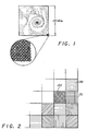
- FIG. 1 a schematic representation of a hologram fabricated in accordance with the present invention may be seen.
- the pattern illustrated in the Figure is a relatively nongeometric pattern, though is defined by a relatively large plurality of individual spots, each of which is a diffraction grating of a predetermined grating separation and angle with respect to the orthogonal axes of the spot matrix.
- each spot in the entire matrix in this example is comprised of a diffraction grating, with the result that different patterns and characteristics of the hologram will be viewable from different angles when the same is illuminated, typically with white light.
- Each spot of course will also have a characteristic color which will vary depending upon the angle of the incident illumination and the observer.
- spots or spot patterns might consist of diffraction gratings, with other areas merely being one or more solid colors or some other form, so that when the same is observed from appropriate angles the design but not the background will appear to have holographic characteristics.
- a free form pattern of spots each of appropriate diffraction grating angle and spacing, may be used rather than the orthogonal spot matrix illustrated, though in general the orthogonal matrix is preferred as being more consistent with computer generation techniques and more readily reproducible by a modified step and repeat process.
- each spot comprises a single circular diffraction grating of parallel, equally spaced grating lines.
- spots of other physical geometries, such as, by way of example, square or rectangular geometries as illustrated in Figure 2 may be used.
- the spots in essence, totally fill the area involved.
- the spots as shown are being shown for illustration purposes only and comprise no specific pattern.
- regions 20 and 22, both of which comprise, in essence, an overlay of two diffraction patterns so as to make the spot, when illuminated, visually active from additional angles and/or with other colors.
- regions 20 and 22 comprise an overlay of diffraction gratings of the same line spacings but with different angles
- overlays with the same angle, but different grating spacing and/or with different angles and different spacings of course are readily useable, depending upon the visual effects desired.
- diffraction gratings comprising curved lines to spread the viewing angle of each spot, such as shown in region 24, may also be used within the principles and concepts of the present invention.
- spot sizes normally will be kept sufficiently small so that the effect achievable by overlaying diffraction grating patterns may be substantially achieved by merely placing the two desired patterns side by side in neighboring spot positions, so that in many cases overlaying of patterns will not be necessary.
- certain methods of forming the diffraction grating patterns of the present invention will readily accommodate the use of overlaying patterns of different spacing and/or angles at the same spot location, though other techniques do not lend themselves well to such overlays.
- a certain pattern may be visible under certain lighting and viewing angle conditions (varying in color as lighting and/or viewing angles change), with another pattern or additional patterns being viewable under other angles of lighting and viewing).
- a hologram in accordance with the present invention might be placed on each football game ticket showing from certain angles the date of the game and from other angles the logo of one or both teams, all in a characteristic multi and varying color pattern so as to not be susceptible to unauthorized duplication.
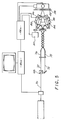
- a block diagram of a system for forming a hologram in accordance with the present invention may be seen.
- a laser 26 directs coherent light to a rotatable head 28 having a diffraction grating mounted therein.
- the diffraction grating aside from passing part of the primary or zero order beam 30, diffracts the incoming beam to create the upper and lower first order beams 32 and 34.
- Beam 30 is blocked by a suitable mask, with beams 32 and 34 being focused to a common point by lens 36 which may be either a glass or a holographic lens.
- the lens should have a small F number, such as, by way of example, in the range of 0.8 to 1.5 so that the two first order beams striking the photosensitive plate 38 are at a sufficient angle to produce a grating with the desired spacing.
- the photosensitive plate 38 itself is mounted on a motorized X-Y table 40 with the bounds of each spot to be exposed being defined and limited by an aperture plate 42 which may define a round, square, or other shaped spot as desired.
- an electronic shutter 44 is provided in the optical path to control the exposure time and, of course, prevent exposure when incrementing the system for the next exposure.
- a computer 46 controls electronic shutter 44 and a three channel servo motor controller 48 to control motor 50 which rotates the diffraction grating 28, and to control the two axis table 40 to successively increment the position of the photosensitive plate 38 from spot location to spot location.
- the angular orientation of the diffraction grating for a spot may be controlled by rotating the head 28 under control of the computer and, of course, exposing the photosensitive plate at a given spot location, with different angle settings of rotating head 28 providing diffraction grating patterns, such as, by way of example, those shown as patterns 20 and 22 in Figure 2.
- the system of Figure 3 will not, however, conveniently allow the variation of the separation of the lines in the diffraction grating, something that can readily be achieved in embodiments hereinafter described.
- computer 46 is used to create the desired pattern, preferably in color on the display 50, each different color representing a different diffraction grating and/or grating angle in accordance with a predetermined relationship or mapping therebetween.
- the print, or expose, operation is initiated.
- the computer controls the two axis table 40 to present the first spot position for exposure, rotates head 28 to the desired diffraction grating angle and opens and closes shutter 44 for the exposure of the respective spot.
- the desired efficiency or brightness of each spot can be controlled by the length of the exposure. If a second grid is to be overlayed on the first, motor 52 is controlled to rotate head 28 to the next desired position and shutter 44 again opened and closed appropriately.
- table 40 is advanced to the next position, head 28 rotated to the desired angular position for that next spot and shutter 44 again opened and closed appropriately so as to expose the respective spot on the photosensitive plate 38.
- the process may be continued under full control of the computer until the exposure of the photosensitive plate 38 or at least a pattern thereon is complete. Thereafter, the same may be developed and reproduced using, by way of example, any of the commonly used techniques for reproducing holograms in general, including contact printing processes, as well as roller and other embossing processes, hot stamping and the like.
- the computer control of the system based upon image information first created on the computer will allow the rapid creation and/or alteration of a design without requiring the production of the corresponding three-dimensional object or alternatively the creation of two-dimensional art work by hand.
- the creation of a hologram which will provide the date as one image and a name identifying the event as another image for authentication of tickets to the event could be generated on the computer screen exceedingly fast, and then automatically converted to an actual exposed and developed hologram for subsequent reproduction very efficiently.
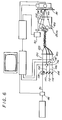
- FIG 4 an alternate embodiment of the apparatus for exposing the photosensitive plate 38 may be seen.
- a rotating head 54 is used, the rotating head having a beam splitter 56 therein for splitting the incoming beam 58 into two beams 60 and 62 which in turn are reflected and pass through lenses 64 and 66 to impinge on the photosensitive plate 38 from opposite sides thereof to form the desired diffraction grating at the angle of the head 54 at the time of the exposure.
- the rotating head 54 be stationary at the desired position, though rotation would appear continuous as the exposure times are sufficiently low.
- a beam splitter 68 splits the original beam 70 into two beams 72 and 74 which are coupled to flexible polarization preserving optical fibers 76 and 78 respectively, coupled to a rotatable head 80.
- the optical fibers are mechanically coupled to slideable arc segments 82 and 84 so as to each point toward the aperture in plate 42 for exposing a spot on the photosensitive plate 38 therebehind, though are variable in angle with respect thereto under control of controller 48a controlled by computer 46a.
- the mirrors are coupled to rotate as required, with the beams being focused as desired by lenses or lens systems 86 and 88.
- the entire head is rotatable by motor 90 under computer control to control the angle of the diffraction grating, with the control of the position of the sliding assemblies 82 and 84 controlling the angle of the beam portions impinging on a spot and thus controlling the spacing of the lines in the interference pattern created thereon.
- the angle of both beam portions is shown as being controllable in Figure 5, normally in unison with each other, the two do not need to be controlled in unison and, in fact, one beam portion may be stationary at some fixed angle with only the other beam portion being controllable to vary the diffraction grating spacing as desired.
- the size of the spot being exposed in comparison to the geometry of the optical system in general will be such that the extent of curvature of the lines of the diffraction grating will normally be fairly minimal.
- the beam 70 from the shutter 44 is split into four components 100, 102, 104 and 106 by beam splitters 108, 110 and 112 and mirror 114.
- Each of the beam components 102, 104 and 106 has an electronically controlled shutter 116, 118 and 120, respectively, in its path.
- the beam component 100 is applied to optical fiber 122 which forms the reference beam on the spot to be exposed on the photosensitive plate 38.
- Beam components 102, 104 and 106 if passed by the respective shutters, are applied to the ends of three other optical fibers to selectively provide one or more corresponding beam components at any of three different angles with respect to the spot surface on the photosensitive plate 38.
- reference beam component 100 together with beam component 102 will provide the interfering beams to generate the diffraction grating at the exposed spot of the photosensitive plate 38. Because of the relatively large angle between beams 100 and 102, the diffraction grating spacing will be relatively small.
- reference beam portion 100 and beam portion 104 will be used, providing a diffraction grating of increased grating spacing with, of course, the use of beam 106 instead of beams 102 and 104, together with beam 100 providing the smallest angle between the two interfering beams and thus the largest grating spacing.
- the entire head 80a is rotatable about an axis perpendicular to the photosensitive plate 38 by motor 90 controlled by the computer, preferably in relatively small increments, such as, by way of example, one degree increments.
- optical fibers and fiber optic bundles may be made relatively flexible, and because zero and 180 degree positions of a diffraction grating are the same, in the limit only a plus or minus ninety degree rotation range for head 80a is required, though a larger angular range is desirable as the same will allow a look-ahead capability to be used to allow rotation of the head 80a through a minimum angle from exposure to exposure in most cases.
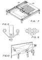
- a hot stamping head 130 is mounted on an X-Y translation system over a thermoplastic substrate 132 which, by way of example, could be as large as a conventional billboard.
- the stamping tool would be a temperature controlled, heated tool which could be rotated about its axis through the desired angular variations of the diffraction gratings.
- the hot stamping head could include a plurality of such tools for variable grating spacing, rotating the desired tool to the stamping position and the same to the desired angle prior to hot stamping each spot on the thermoplastic substrate.
- spot sizes will be proportionately larger.
- the circular spots of Figure 1 are convenient, or alternatively other shapes could also be used, such as by way of example, the six sided regular polygon so that the same may be interlaced as shown in Figure 8 to provide a selection of three diffraction grating angles and yet still cover the entire area.
- thermoplastic substrate 132 may be provided in roll form and transferred line by line between two rolls, with the X-Y drive system of Figure 7 merely having a lateral drive system, the longitudinal drive effectively being accomplished by advancing the thermoplastic material one spot width after each lateral line of the pattern is formed.
- the diffraction gratings may be provided as transfers on a tape as illustrated in Figure 9 and transferred to the substrate at each spot position at the appropriate angle by rotating the transfer tape support and takeup reel, etc. to the appropriate angle before the transfer for each spot is accomplished.
- Such a transfer technique could be used, by way of example, with the systems of Figures 8 and 13.
- a hologram will provide an attractive image for billboards whereby a particular group of spots create an image at a specific angle of view and illumination, which will change with the angle of view and/or illumination.
- a sign might display one message illuminated by the morning sun, another message by the afternoon sun and a still further message when lit at night.
- a billboard fabricated in accordance with the present invention might be illuminated from three different positions as shown in Figure 10 so that the people at different positions will see different patterns or messages from the same billboard.
- the lighting might be changed with time so that all patterns could be viewed over a period of time from one position, either by cycling through the lights one by one or by bringing one up slowly as a previous light source fades down so that one message or pattern fades into another, or two complimentary images are viewable at the same time.
- FIG 11 an embodiment similar to that of Figure 3 may be seen, the embodiment of Figure 11 further including the capability of varying the grating spacing as well as the grating angle.
- components which may be substantially identical to those of Figure 3 and function in the same general manner are identified with the same numerals.
- two motors 52a and 52b are provided, each controllably rotating members 28a and 28b comprising a variable diffraction grating assembly as shown in Figure 12.
- a rotating head 140 carries a number of diffraction gratings 142, 144, etc.
- the diffraction grating member 140 eight being shown in the figure, are each of a different grating spacing, for simplicity each being angularly oriented so that rotation of member 140 in angular increments of 45 degrees and multiples thereof will bring a new diffraction grating onto the axis of the assembly, though each with the same angular orientation when so disposed.
- Schematically illustrated in the figure is a gear 146 driving the periphery of member 140, with a larger gear 148 driven by member 28b ( Figure 11) being connected to and driving gear 146.
- a single rotation of member 28b by motor 52b will rotate the diffraction grating member 140 also through a single rotation.
- a rotation of member 28a by motor 52a on the other hand, will rotate a member supporting the axes of members 140 and gears 146 and 148.
- the rotation of members 28a and 28b in unison will rotate the entire assembly about the optical axis, thereby rotating the diffraction grating which is aligned with the optical axis to any desired angle (Preferably in relatively small increments of, say, 1 degree and multiples thereof).
- any of eight diffraction gratings may be aligned with the optical axis of the system, with all of them when so aligned being rotatable about the optical axis in relatively small angular increments, such as 1 degree.
- a drive motor may be provided on the rotatable head for rotating member 140, though such a scheme would require slip rings or some other means of providing power to the rotating assembly.
- the diffraction grating might slide onto and away from the optical axis of the system under the influence of gravity, this being particularly facilitated by the fact that the diffraction grating angles repeat every 180 degrees rather than every 360 degrees, allowing one grating to be in place over a 180 degree range of head rotation to provide the full grating rotation capability, and the other grating to be in position over the other 180 degree head rotation to provide the full grating angle range for the second grating.
Landscapes
- Physics & Mathematics (AREA)
- General Physics & Mathematics (AREA)
- Optics & Photonics (AREA)
- Holo Graphy (AREA)
- Diffracting Gratings Or Hologram Optical Elements (AREA)
Applications Claiming Priority (2)
| Application Number | Priority Date | Filing Date | Title |
|---|---|---|---|
| US552258 | 1990-07-12 | ||
| US07/552,258 US5291317A (en) | 1990-07-12 | 1990-07-12 | Holographic diffraction grating patterns and methods for creating the same |
Publications (3)
| Publication Number | Publication Date |
|---|---|
| EP0467601A2 true EP0467601A2 (de) | 1992-01-22 |
| EP0467601A3 EP0467601A3 (en) | 1992-03-04 |
| EP0467601B1 EP0467601B1 (de) | 1996-02-28 |
Family
ID=24204581
Family Applications (1)
| Application Number | Title | Priority Date | Filing Date |
|---|---|---|---|
| EP91306316A Expired - Lifetime EP0467601B1 (de) | 1990-07-12 | 1991-07-11 | Holographische Beugungsgitterstrukturen und Herstellungsverfahren |
Country Status (5)
| Country | Link |
|---|---|
| US (1) | US5291317A (de) |
| EP (1) | EP0467601B1 (de) |
| JP (1) | JPH0675107A (de) |
| DE (1) | DE69117369T2 (de) |
| ES (1) | ES2087246T3 (de) |
Cited By (30)
| Publication number | Priority date | Publication date | Assignee | Title |
|---|---|---|---|---|
| EP0534616A3 (en) * | 1991-08-29 | 1993-08-11 | Fujitsu Limited | Holographic recording apparatus and holographic optical element |
| WO1993018419A1 (en) * | 1992-03-12 | 1993-09-16 | Commonwealth Scientific And Industrial Research Organisation | Security diffraction grating with special optical effects |
| EP0497292A3 (de) * | 1991-01-29 | 1994-02-16 | Toppan Printing Co Ltd | |
| EP0604039A3 (de) * | 1992-12-23 | 1994-08-31 | At & T Corp | |
| WO1994028444A1 (en) * | 1993-05-25 | 1994-12-08 | Commonwealth Scientific And Industrial Research Organisation | Multiple image diffractive device |
| WO1995002200A1 (en) * | 1993-07-09 | 1995-01-19 | Commonwealth Scientific And Industrial Research Organisation | Multiple image diffractive device |
| EP0617396A3 (de) * | 1992-10-10 | 1996-08-14 | Martin Hoerdum | Grosse Transmissions-Regenbogenhologramme für wetterfeste, weit sichtbare Werbeflächen. |
| EP0730753A4 (de) * | 1993-11-23 | 1997-02-26 | Commw Scient Ind Res Org | Diffraktive markierungen einer fläche |
| EP0699979A3 (de) * | 1994-08-31 | 1997-10-29 | Toppan Printing Co Ltd | Hologramm in welchem eine Vielzahl von Bereichen angeordnet sind und holographisches System bei welchem das Hologramm angewendet wird |
| US5822092A (en) * | 1988-07-18 | 1998-10-13 | Dimensional Arts | System for making a hologram of an image by manipulating object beam characteristics to reflect image data |
| US5825547A (en) * | 1993-08-06 | 1998-10-20 | Commonwealth Scientific And Industrial Research Organisation | Diffractive device for generating one or more diffracting images including a surface relief structure at least partly arranged in a series of tracks |
| GB2335288A (en) * | 1998-02-10 | 1999-09-15 | Pennsylvania Pulp And Paper Co | Producing holographic patterns |
| US5991078A (en) * | 1992-08-19 | 1999-11-23 | Dai Nippon Printing Co., Ltd. | Display medium employing diffraction grating and method of producing diffraction grating assembly |
| EP0934540A4 (de) * | 1996-10-28 | 2000-11-15 | Pacific Holographics Inc | Vorrichtung und verfahren zur erzeugung eines diffraktiven elements unter verwendung einer flüssigkristallanzeige |
| US6388780B1 (en) | 2000-05-11 | 2002-05-14 | Illinois Tool Works Inc. | Hologram production technique |
| US6392768B1 (en) * | 1999-09-16 | 2002-05-21 | Ahead Optoelectronics, Inc. | Dot matrix hologram with a hidden image |
| EP0876629B1 (de) * | 1996-01-26 | 2002-08-14 | OVD Kinegram AG | Oberflächenmuster |
| US6835948B2 (en) | 2002-09-10 | 2004-12-28 | Illinois Tool Works, Inc. | Holographic or optically variable printing material and method for customized printing |
| EP1564606A3 (de) * | 2004-02-05 | 2005-08-24 | Illinois Tool Works Inc. | Farbliches holographisches Druckmaterial |
| WO2006108539A2 (de) | 2005-04-14 | 2006-10-19 | Giesecke & Devrient Gmbh | Beugungsgitter und verfahren zu seiner herstellung |
| CZ297552B6 (cs) * | 2001-06-15 | 2007-02-07 | Ceské vysoké ucení technické v Praze, Fakulta jaderná a fyzikálne inzenýrská | Zpusob zhotovení opticky variabilních difraktivních struktur a zarízení k jeho provádení |
| EP1979786A4 (de) * | 2006-01-30 | 2009-12-16 | 3Dcd Llc | Optisch variables vorrichtungssteuersystem, verfahren zur authentifizierung von artikeln damit und daraus entstandener artikel |
| US7710652B2 (en) | 2004-01-26 | 2010-05-04 | Giesecke & Devrient, Gmbh | Grid image with one or several grid fields |
| EP1059574B1 (de) * | 1998-02-27 | 2012-08-22 | Hideyoshi Horimai | Verfahren und vorrichtung zur herstellung eines hologramms |
| EP2506089A2 (de) * | 2000-05-30 | 2012-10-03 | Dai Nippon Printing Co., Ltd. | Computererzeugtes Hologramm und sein Herstellungsprozess, Reflektor mit einem computererzeugten Hologramm und reflektierende Flüssigkristallanzeige |
| US8284234B2 (en) | 2009-03-20 | 2012-10-09 | Absolute Imaging LLC | Endoscopic imaging using reflection holographic optical element for autostereoscopic 3-D viewing |
| WO2013087447A1 (de) * | 2011-12-16 | 2013-06-20 | Eads Deutschland Gmbh | Verfahren und vorrichtung zur herstellung eines holographischen bildschirmes für elektronische aufprojektion |
| US8684417B2 (en) | 2004-12-23 | 2014-04-01 | Arjowiggins Security | Security element having a digitised mark and security support or document comprising same |
| EP2312345A3 (de) * | 2009-10-13 | 2014-05-07 | Giesecke & Devrient GmbH | Gitterbild mit aneinandergrenzenden Gitterfeldern |
| FR3066142A1 (fr) | 2017-05-12 | 2018-11-16 | Ccl Secure Pty Ltd | Dispositif de securite optique et procede de fabrication |
Families Citing this family (116)
| Publication number | Priority date | Publication date | Assignee | Title |
|---|---|---|---|---|
| US6219015B1 (en) | 1992-04-28 | 2001-04-17 | The Board Of Directors Of The Leland Stanford, Junior University | Method and apparatus for using an array of grating light valves to produce multicolor optical images |
| DE69327809T2 (de) | 1992-11-27 | 2000-10-12 | Voxel, Laguna Hills | Verfahren und vorrichtung zur herstellung von hologrammen |
| US5581378A (en) * | 1993-02-01 | 1996-12-03 | University Of Alabama At Huntsville | Electro-optical holographic display |
| WO1995012149A1 (en) * | 1993-10-25 | 1995-05-04 | Dimensional Arts, Inc. | System for making a hologram |
| CA2183979A1 (en) * | 1994-02-28 | 1995-08-31 | Peter Leigh-Jones | Difraction surfaces and methods for the manufacture thereof |
| US5798743A (en) * | 1995-06-07 | 1998-08-25 | Silicon Light Machines | Clear-behind matrix addressing for display systems |
| WO1996041331A1 (en) * | 1995-06-07 | 1996-12-19 | Gregory Barrington, Ltd. | Free-vision three-dimensional image with enhanced viewing |
| US5629801A (en) * | 1995-06-07 | 1997-05-13 | Silicon Light Machines | Diffraction grating light doubling collection system |
| US5661592A (en) * | 1995-06-07 | 1997-08-26 | Silicon Light Machines | Method of making and an apparatus for a flat diffraction grating light valve |
| US5841579A (en) | 1995-06-07 | 1998-11-24 | Silicon Light Machines | Flat diffraction grating light valve |
| US5729365A (en) * | 1996-01-11 | 1998-03-17 | Sandia Corporation | Computer generated holographic microtags |
| DE19623352C2 (de) * | 1996-06-12 | 1999-11-11 | Kurz Leonhard Fa | Verfahren zur Herstellung von eine räumlich gemusterte Oberfläche aufweisenden Druck- oder Prägezylindern |
| US7312906B2 (en) * | 1996-07-12 | 2007-12-25 | Science Applications International Corporation | Switchable polymer-dispersed liquid crystal optical elements |
| US6867888B2 (en) * | 1996-07-12 | 2005-03-15 | Science Applications International Corporation | Switchable polymer-dispersed liquid crystal optical elements |
| US7077984B1 (en) | 1996-07-12 | 2006-07-18 | Science Applications International Corporation | Electrically switchable polymer-dispersed liquid crystal materials |
| US5942157A (en) * | 1996-07-12 | 1999-08-24 | Science Applications International Corporation | Switchable volume hologram materials and devices |
| US6821457B1 (en) | 1998-07-29 | 2004-11-23 | Science Applications International Corporation | Electrically switchable polymer-dispersed liquid crystal materials including switchable optical couplers and reconfigurable optical interconnects |
| US6064404A (en) * | 1996-11-05 | 2000-05-16 | Silicon Light Machines | Bandwidth and frame buffer size reduction in a digital pulse-width-modulated display system |
| US5982553A (en) | 1997-03-20 | 1999-11-09 | Silicon Light Machines | Display device incorporating one-dimensional grating light-valve array |
| CN1053118C (zh) * | 1997-07-09 | 2000-06-07 | 天津市元亨医药保健品公司 | 强心卡及其制造方法 |
| US6088102A (en) | 1997-10-31 | 2000-07-11 | Silicon Light Machines | Display apparatus including grating light-valve array and interferometric optical system |
| US6330088B1 (en) * | 1998-02-27 | 2001-12-11 | Zebra Imaging, Inc. | Method and apparatus for recording one-step, full-color, full-parallax, holographic stereograms |
| US6271808B1 (en) | 1998-06-05 | 2001-08-07 | Silicon Light Machines | Stereo head mounted display using a single display device |
| US6101036A (en) | 1998-06-23 | 2000-08-08 | Silicon Light Machines | Embossed diffraction grating alone and in combination with changeable image display |
| US6130770A (en) | 1998-06-23 | 2000-10-10 | Silicon Light Machines | Electron gun activated grating light valve |
| US6215579B1 (en) | 1998-06-24 | 2001-04-10 | Silicon Light Machines | Method and apparatus for modulating an incident light beam for forming a two-dimensional image |
| US6303986B1 (en) | 1998-07-29 | 2001-10-16 | Silicon Light Machines | Method of and apparatus for sealing an hermetic lid to a semiconductor die |
| US6872984B1 (en) | 1998-07-29 | 2005-03-29 | Silicon Light Machines Corporation | Method of sealing a hermetic lid to a semiconductor die at an angle |
| US6342960B1 (en) | 1998-12-18 | 2002-01-29 | The Boeing Company | Wavelength division multiplex transmitter |
| AU3368300A (en) * | 1999-02-16 | 2000-09-04 | Zebra Imaging, Inc. | System and method for producing and displaying a one-step, edge-lit hologram |
| IL131575A (en) | 1999-08-24 | 2003-11-23 | U C Laser Ltd | Volume holograms in transparent materials |
| US6882477B1 (en) | 1999-11-10 | 2005-04-19 | Massachusetts Institute Of Technology | Method and system for interference lithography utilizing phase-locked scanning beams |
| US6956878B1 (en) | 2000-02-07 | 2005-10-18 | Silicon Light Machines Corporation | Method and apparatus for reducing laser speckle using polarization averaging |
| US6730442B1 (en) | 2000-05-24 | 2004-05-04 | Science Applications International Corporation | System and method for replicating volume holograms |
| US6884961B1 (en) | 2000-08-24 | 2005-04-26 | Uc Laser Ltd. | Intravolume diffractive optical elements |
| US20020037477A1 (en) * | 2000-09-05 | 2002-03-28 | Flynn Charles J. | System and method of creating prism line patterns for a laser foil die |
| DE10044465A1 (de) * | 2000-09-08 | 2002-03-21 | Giesecke & Devrient Gmbh | Datenträger mit einem optisch variablen Element |
| US7177081B2 (en) | 2001-03-08 | 2007-02-13 | Silicon Light Machines Corporation | High contrast grating light valve type device |
| US6865346B1 (en) | 2001-06-05 | 2005-03-08 | Silicon Light Machines Corporation | Fiber optic transceiver |
| US6782205B2 (en) | 2001-06-25 | 2004-08-24 | Silicon Light Machines | Method and apparatus for dynamic equalization in wavelength division multiplexing |
| US6747781B2 (en) | 2001-06-25 | 2004-06-08 | Silicon Light Machines, Inc. | Method, apparatus, and diffuser for reducing laser speckle |
| RU2207611C2 (ru) * | 2001-07-30 | 2003-06-27 | Бондарев Леонид Алексеевич | Устройство для изготовления радужных голограмм |
| RU2216758C2 (ru) * | 2001-07-30 | 2003-11-20 | Бондарев Леонид Алексеевич | Устройство для изготовления радужных голограмм |
| US6829092B2 (en) | 2001-08-15 | 2004-12-07 | Silicon Light Machines, Inc. | Blazed grating light valve |
| US6930364B2 (en) | 2001-09-13 | 2005-08-16 | Silicon Light Machines Corporation | Microelectronic mechanical system and methods |
| US6712121B2 (en) * | 2001-10-12 | 2004-03-30 | Kimberly-Clark Worldwide, Inc. | Antimicrobially-treated fabrics |
| US6956995B1 (en) | 2001-11-09 | 2005-10-18 | Silicon Light Machines Corporation | Optical communication arrangement |
| US6800238B1 (en) | 2002-01-15 | 2004-10-05 | Silicon Light Machines, Inc. | Method for domain patterning in low coercive field ferroelectrics |
| US6767751B2 (en) | 2002-05-28 | 2004-07-27 | Silicon Light Machines, Inc. | Integrated driver process flow |
| US7054515B1 (en) | 2002-05-30 | 2006-05-30 | Silicon Light Machines Corporation | Diffractive light modulator-based dynamic equalizer with integrated spectral monitor |
| US6822797B1 (en) | 2002-05-31 | 2004-11-23 | Silicon Light Machines, Inc. | Light modulator structure for producing high-contrast operation using zero-order light |
| US6829258B1 (en) | 2002-06-26 | 2004-12-07 | Silicon Light Machines, Inc. | Rapidly tunable external cavity laser |
| US6813059B2 (en) | 2002-06-28 | 2004-11-02 | Silicon Light Machines, Inc. | Reduced formation of asperities in contact micro-structures |
| US6714337B1 (en) | 2002-06-28 | 2004-03-30 | Silicon Light Machines | Method and device for modulating a light beam and having an improved gamma response |
| US6908201B2 (en) | 2002-06-28 | 2005-06-21 | Silicon Light Machines Corporation | Micro-support structures |
| US6801354B1 (en) | 2002-08-20 | 2004-10-05 | Silicon Light Machines, Inc. | 2-D diffraction grating for substantially eliminating polarization dependent losses |
| US7057795B2 (en) | 2002-08-20 | 2006-06-06 | Silicon Light Machines Corporation | Micro-structures with individually addressable ribbon pairs |
| US7619739B1 (en) | 2002-08-29 | 2009-11-17 | Science Applications International Corporation | Detection and identification of biological agents using Bragg filters |
| US6712480B1 (en) | 2002-09-27 | 2004-03-30 | Silicon Light Machines | Controlled curvature of stressed micro-structures |
| US7018563B1 (en) | 2002-11-26 | 2006-03-28 | Science Applications International Corporation | Tailoring material composition for optimization of application-specific switchable holograms |
| US6928207B1 (en) | 2002-12-12 | 2005-08-09 | Silicon Light Machines Corporation | Apparatus for selectively blocking WDM channels |
| US6987600B1 (en) | 2002-12-17 | 2006-01-17 | Silicon Light Machines Corporation | Arbitrary phase profile for better equalization in dynamic gain equalizer |
| US7057819B1 (en) | 2002-12-17 | 2006-06-06 | Silicon Light Machines Corporation | High contrast tilting ribbon blazed grating |
| US6934070B1 (en) | 2002-12-18 | 2005-08-23 | Silicon Light Machines Corporation | Chirped optical MEM device |
| US6927891B1 (en) | 2002-12-23 | 2005-08-09 | Silicon Light Machines Corporation | Tilt-able grating plane for improved crosstalk in 1×N blaze switches |
| US7068372B1 (en) | 2003-01-28 | 2006-06-27 | Silicon Light Machines Corporation | MEMS interferometer-based reconfigurable optical add-and-drop multiplexor |
| US7286764B1 (en) | 2003-02-03 | 2007-10-23 | Silicon Light Machines Corporation | Reconfigurable modulator-based optical add-and-drop multiplexer |
| US6947613B1 (en) | 2003-02-11 | 2005-09-20 | Silicon Light Machines Corporation | Wavelength selective switch and equalizer |
| US6922272B1 (en) | 2003-02-14 | 2005-07-26 | Silicon Light Machines Corporation | Method and apparatus for leveling thermal stress variations in multi-layer MEMS devices |
| US6922273B1 (en) | 2003-02-28 | 2005-07-26 | Silicon Light Machines Corporation | PDL mitigation structure for diffractive MEMS and gratings |
| US6829077B1 (en) | 2003-02-28 | 2004-12-07 | Silicon Light Machines, Inc. | Diffractive light modulator with dynamically rotatable diffraction plane |
| US7027202B1 (en) | 2003-02-28 | 2006-04-11 | Silicon Light Machines Corp | Silicon substrate as a light modulator sacrificial layer |
| US7391973B1 (en) | 2003-02-28 | 2008-06-24 | Silicon Light Machines Corporation | Two-stage gain equalizer |
| US6806997B1 (en) | 2003-02-28 | 2004-10-19 | Silicon Light Machines, Inc. | Patterned diffractive light modulator ribbon for PDL reduction |
| US7042611B1 (en) | 2003-03-03 | 2006-05-09 | Silicon Light Machines Corporation | Pre-deflected bias ribbons |
| US6775037B1 (en) | 2003-03-20 | 2004-08-10 | K Laser Technology, Inc. | Grating matrix recording system |
| BR0318178A (pt) * | 2003-03-25 | 2006-03-21 | Imprensa Nac Casa Da Moeda S A | litografia interferométrica ótica sem máscara |
| US6950173B1 (en) | 2003-04-08 | 2005-09-27 | Science Applications International Corporation | Optimizing performance parameters for switchable polymer dispersed liquid crystal optical elements |
| US7057779B2 (en) | 2003-05-21 | 2006-06-06 | K Laser Technology, Inc. | Holographic stereogram device |
| WO2005008346A1 (de) * | 2003-07-11 | 2005-01-27 | Tesa Scribos Gmbh | Verfahren zum berechnen und erzeugen eines computergenerierten dotmatrix-hologramms sowie speichermedium mit einem solchen hologramm |
| DE10348623A1 (de) | 2003-10-15 | 2005-05-25 | Giesecke & Devrient Gmbh | Optisch variable Beugungsstruktur und Verfahren zu ihrer Herstellung |
| TWI264610B (en) * | 2005-02-15 | 2006-10-21 | Benq Corp | Recording system for light-sensitive sheet |
| WO2007089770A2 (en) * | 2006-01-31 | 2007-08-09 | Polychromix Corporation | Hand-held ir spectrometer with a fixed grating and a diffractive mems-array |
| JP4826292B2 (ja) * | 2006-03-08 | 2011-11-30 | 大日本印刷株式会社 | 光学異方性媒体作成システム、および、その方法 |
| JP5488581B2 (ja) * | 2006-08-22 | 2014-05-14 | 大日本印刷株式会社 | 立体模様が表現された回折格子記録媒体の作成方法 |
| US7891818B2 (en) | 2006-12-12 | 2011-02-22 | Evans & Sutherland Computer Corporation | System and method for aligning RGB light in a single modulator projector |
| JP4974711B2 (ja) * | 2007-03-05 | 2012-07-11 | 富士フイルム株式会社 | 印刷装置 |
| TWI413868B (zh) * | 2007-06-12 | 2013-11-01 | Ind Tech Res Inst | 製作週期性圖案的步進排列式干涉微影方法及其裝置 |
| GB0711434D0 (en) * | 2007-06-13 | 2007-07-25 | Rue De Int Ltd | Holographic security device |
| WO2009005746A1 (en) * | 2007-06-29 | 2009-01-08 | Allview Research Llc | Writing a diffractive structure |
| US8358317B2 (en) | 2008-05-23 | 2013-01-22 | Evans & Sutherland Computer Corporation | System and method for displaying a planar image on a curved surface |
| US8702248B1 (en) | 2008-06-11 | 2014-04-22 | Evans & Sutherland Computer Corporation | Projection method for reducing interpixel gaps on a viewing surface |
| US20090317062A1 (en) * | 2008-06-24 | 2009-12-24 | Samsung Electronics Co., Ltd. | Image processing method and apparatus |
| KR101539935B1 (ko) * | 2008-06-24 | 2015-07-28 | 삼성전자주식회사 | 3차원 비디오 영상 처리 방법 및 장치 |
| KR101560617B1 (ko) * | 2008-09-10 | 2015-10-16 | 삼성전자주식회사 | 광 발생 장치 및 그 제어 방법 |
| US8077378B1 (en) | 2008-11-12 | 2011-12-13 | Evans & Sutherland Computer Corporation | Calibration system and method for light modulation device |
| US9134008B2 (en) | 2010-10-06 | 2015-09-15 | Shoot The Moon Products Ii, Llc | Light emitting decorative panels |
| US9200781B2 (en) | 2010-10-06 | 2015-12-01 | Shoot The Moon Products Ii, Llc | Light emitting decorative panels |
| CN102722095B (zh) * | 2011-03-30 | 2015-04-15 | 武汉思臻光信息科技有限公司 | 一种用于生成全息干涉条纹的方法及系统 |
| JP2013007842A (ja) * | 2011-06-23 | 2013-01-10 | Toyo Seikan Kaisha Ltd | 構造体形成装置、構造体形成方法及び構造体 |
| US9641826B1 (en) | 2011-10-06 | 2017-05-02 | Evans & Sutherland Computer Corporation | System and method for displaying distant 3-D stereo on a dome surface |
| WO2014086715A1 (de) * | 2012-12-04 | 2014-06-12 | Sectago Gmbh | Sicherheitseinrichtung |
| US10207531B2 (en) | 2013-12-02 | 2019-02-19 | SECTAG GmbH | Security device |
| EP3210069A4 (de) | 2014-10-24 | 2018-05-30 | Wavefront Technology, Inc. | Optische produkte, vorlagen zur herstellung optischer produkte und verfahren zur herstellung von vorlagen und optischen produkte |
| DE102015110626A1 (de) * | 2015-07-01 | 2017-01-05 | Sectago Gmbh | Optische Sicherheitsvorrichtung |
| CA2992060A1 (en) | 2015-07-13 | 2017-01-19 | Wavefront Technology, Inc. | Optical products, masters for fabricating optical products, and methods for manufacturing masters and optical products |
| JP6953109B2 (ja) * | 2015-09-24 | 2021-10-27 | ウシオ電機株式会社 | 基板上構造体の製造方法 |
| US12589611B2 (en) | 2016-04-22 | 2026-03-31 | Hueck Folien Gesellschaft M.B.H. | Optical switch devices |
| EP3405353A4 (de) | 2016-04-22 | 2019-11-06 | Wavefront Technology, Inc. | Optische schaltvorrichtungen |
| US11221448B2 (en) | 2019-04-19 | 2022-01-11 | Wavefront Technology, Inc. | Animated optical security feature |
| WO2019077419A1 (en) | 2017-10-20 | 2019-04-25 | Wavefront Technology, Inc. | OPTICAL SWITCH DEVICES |
| CN110806388B (zh) * | 2019-11-20 | 2022-05-27 | 河南牧业经济学院 | 柱状镭射纸的暗光柱定位装置、定位方法及颜色测量方法 |
| WO2022077011A1 (en) | 2020-10-07 | 2022-04-14 | Wavefront Technology, Inc. | Optical products, masters for fabricating optical products, and methods for manufacturing masters and optical products |
| WO2022077012A1 (en) | 2020-10-07 | 2022-04-14 | Wavefront Technology, Inc. | Optical products, masters for fabricating optical products, and methods for manufacturing masters and optical products |
| EP4067102A1 (de) | 2021-04-02 | 2022-10-05 | Kaunas University of Technology | Optische vorrichtung mit geordneten streuer-arrays für sichere identität und verfahren zu deren herstellung |
| CN120897845A (zh) | 2023-03-27 | 2025-11-04 | 法国圣戈班安全玻璃公司 | 具有用于耦合入光的衍射全息元件的照明窗玻璃元件 |
Family Cites Families (14)
| Publication number | Priority date | Publication date | Assignee | Title |
|---|---|---|---|---|
| US3567561A (en) * | 1969-01-09 | 1971-03-02 | Remsen V Wood | Diffraction type mosaic system |
| US3947105A (en) * | 1973-09-21 | 1976-03-30 | Technical Operations, Incorporated | Production of colored designs |
| US4036552A (en) * | 1975-02-10 | 1977-07-19 | Minnesota Mining And Manufacturing Company | Retroreflective material made by recording a plurality of light interference fringe patterns |
| US4034211A (en) * | 1975-06-20 | 1977-07-05 | Ncr Corporation | System and method for providing a security check on a credit card |
| US4455061A (en) * | 1980-07-31 | 1984-06-19 | The Regents Of The University Of Minnesota | Multi-faceted holographic optical element and methods of making and using same |
| US4547037A (en) * | 1980-10-16 | 1985-10-15 | Regents Of The University Of Minnesota | Holographic method for producing desired wavefront transformations |
| CH659433A5 (de) * | 1982-10-04 | 1987-01-30 | Landis & Gyr Ag | Dokument mit einem beugungsoptischen sicherheitselement. |
| JPS5988780A (ja) * | 1982-11-08 | 1984-05-22 | アメリカン・バンク・ノ−ト・カムパニ− | 光回折記録体及び光回折パタ−ンを作る方法 |
| JPS60156004A (ja) * | 1984-01-12 | 1985-08-16 | Toppan Printing Co Ltd | 回折格子露光装置 |
| US4788116A (en) * | 1986-03-31 | 1988-11-29 | Xerox Corporation | Full color images using multiple diffraction gratings and masking techniques |
| US5058992A (en) * | 1988-09-07 | 1991-10-22 | Toppan Printing Co., Ltd. | Method for producing a display with a diffraction grating pattern and a display produced by the method |
| EP0375833B1 (de) * | 1988-12-12 | 1993-02-10 | Landis & Gyr Technology Innovation AG | Optisch variables Flächenmuster |
| ATE133271T1 (de) * | 1988-12-19 | 1996-02-15 | Australia Reserve Bank | Diffraktionsgitter |
| US5056880A (en) * | 1990-04-08 | 1991-10-15 | Dz Company | Holographic wallpaper |
-
1990
- 1990-07-12 US US07/552,258 patent/US5291317A/en not_active Expired - Lifetime
-
1991
- 1991-07-11 DE DE69117369T patent/DE69117369T2/de not_active Expired - Lifetime
- 1991-07-11 EP EP91306316A patent/EP0467601B1/de not_active Expired - Lifetime
- 1991-07-11 ES ES91306316T patent/ES2087246T3/es not_active Expired - Lifetime
- 1991-07-12 JP JP3197468A patent/JPH0675107A/ja active Pending
Cited By (42)
| Publication number | Priority date | Publication date | Assignee | Title |
|---|---|---|---|---|
| US5822092A (en) * | 1988-07-18 | 1998-10-13 | Dimensional Arts | System for making a hologram of an image by manipulating object beam characteristics to reflect image data |
| US6486982B1 (en) | 1988-07-18 | 2002-11-26 | Illinois Tool Works Inc. | System for making a hologram of an image by manipulating object beam characteristics to reflect image data |
| EP0497292A3 (de) * | 1991-01-29 | 1994-02-16 | Toppan Printing Co Ltd | |
| US5301062A (en) * | 1991-01-29 | 1994-04-05 | Toppan Printing Co., Ltd. | Display having diffraction grating pattern |
| EP0534616A3 (en) * | 1991-08-29 | 1993-08-11 | Fujitsu Limited | Holographic recording apparatus and holographic optical element |
| US5892597A (en) * | 1991-08-29 | 1999-04-06 | Fujitsu Limited | Holographic recording apparatus and holographic optical element |
| WO1993018419A1 (en) * | 1992-03-12 | 1993-09-16 | Commonwealth Scientific And Industrial Research Organisation | Security diffraction grating with special optical effects |
| US5991078A (en) * | 1992-08-19 | 1999-11-23 | Dai Nippon Printing Co., Ltd. | Display medium employing diffraction grating and method of producing diffraction grating assembly |
| EP0617396A3 (de) * | 1992-10-10 | 1996-08-14 | Martin Hoerdum | Grosse Transmissions-Regenbogenhologramme für wetterfeste, weit sichtbare Werbeflächen. |
| EP0604039A3 (de) * | 1992-12-23 | 1994-08-31 | At & T Corp | |
| US6342969B1 (en) | 1993-05-25 | 2002-01-29 | Commonwealth Scientific/Industrial Research Organization | Multiple image diffractive device |
| WO1994028444A1 (en) * | 1993-05-25 | 1994-12-08 | Commonwealth Scientific And Industrial Research Organisation | Multiple image diffractive device |
| US5909313A (en) * | 1993-05-25 | 1999-06-01 | Commonwealth Scientific And Industrial Research Organisation | Multiple image diffractive device |
| WO1995002200A1 (en) * | 1993-07-09 | 1995-01-19 | Commonwealth Scientific And Industrial Research Organisation | Multiple image diffractive device |
| US5825547A (en) * | 1993-08-06 | 1998-10-20 | Commonwealth Scientific And Industrial Research Organisation | Diffractive device for generating one or more diffracting images including a surface relief structure at least partly arranged in a series of tracks |
| US5912767A (en) * | 1993-11-23 | 1999-06-15 | Commonwealth Scientific And Industrial Research Organisation | Diffractive indicia for a surface |
| EP0730753A4 (de) * | 1993-11-23 | 1997-02-26 | Commw Scient Ind Res Org | Diffraktive markierungen einer fläche |
| EP0699979A3 (de) * | 1994-08-31 | 1997-10-29 | Toppan Printing Co Ltd | Hologramm in welchem eine Vielzahl von Bereichen angeordnet sind und holographisches System bei welchem das Hologramm angewendet wird |
| EP0876629B1 (de) * | 1996-01-26 | 2002-08-14 | OVD Kinegram AG | Oberflächenmuster |
| EP0934540A4 (de) * | 1996-10-28 | 2000-11-15 | Pacific Holographics Inc | Vorrichtung und verfahren zur erzeugung eines diffraktiven elements unter verwendung einer flüssigkristallanzeige |
| US6806983B2 (en) | 1996-10-28 | 2004-10-19 | Pacific Holographics, Inc. | Apparatus and method for generating diffractive element using liquid crystal display |
| GB2335288B (en) * | 1998-02-10 | 2002-03-13 | Pennsylvania Pulp And Paper Co | Holography apparatus, method and product |
| GB2335288A (en) * | 1998-02-10 | 1999-09-15 | Pennsylvania Pulp And Paper Co | Producing holographic patterns |
| US6549309B1 (en) | 1998-02-10 | 2003-04-15 | Illinois Tool Works Inc. | Holography apparatus, method and product |
| EP1059574B1 (de) * | 1998-02-27 | 2012-08-22 | Hideyoshi Horimai | Verfahren und vorrichtung zur herstellung eines hologramms |
| US6392768B1 (en) * | 1999-09-16 | 2002-05-21 | Ahead Optoelectronics, Inc. | Dot matrix hologram with a hidden image |
| US6388780B1 (en) | 2000-05-11 | 2002-05-14 | Illinois Tool Works Inc. | Hologram production technique |
| AU775021B2 (en) * | 2000-05-11 | 2004-07-15 | Illinois Tool Works Inc. | Hologram production technique |
| US6567193B2 (en) | 2000-05-11 | 2003-05-20 | Illinois Tool Works, Inc. | Hologram production technique |
| EP2506089A2 (de) * | 2000-05-30 | 2012-10-03 | Dai Nippon Printing Co., Ltd. | Computererzeugtes Hologramm und sein Herstellungsprozess, Reflektor mit einem computererzeugten Hologramm und reflektierende Flüssigkristallanzeige |
| CZ297552B6 (cs) * | 2001-06-15 | 2007-02-07 | Ceské vysoké ucení technické v Praze, Fakulta jaderná a fyzikálne inzenýrská | Zpusob zhotovení opticky variabilních difraktivních struktur a zarízení k jeho provádení |
| US6835948B2 (en) | 2002-09-10 | 2004-12-28 | Illinois Tool Works, Inc. | Holographic or optically variable printing material and method for customized printing |
| WO2004025378A3 (en) * | 2002-09-10 | 2005-08-11 | Illinois Tool Works | Holographic or optically variable printing material and method for customized printing |
| US7710652B2 (en) | 2004-01-26 | 2010-05-04 | Giesecke & Devrient, Gmbh | Grid image with one or several grid fields |
| EP1564606A3 (de) * | 2004-02-05 | 2005-08-24 | Illinois Tool Works Inc. | Farbliches holographisches Druckmaterial |
| US8684417B2 (en) | 2004-12-23 | 2014-04-01 | Arjowiggins Security | Security element having a digitised mark and security support or document comprising same |
| WO2006108539A2 (de) | 2005-04-14 | 2006-10-19 | Giesecke & Devrient Gmbh | Beugungsgitter und verfahren zu seiner herstellung |
| EP1979786A4 (de) * | 2006-01-30 | 2009-12-16 | 3Dcd Llc | Optisch variables vorrichtungssteuersystem, verfahren zur authentifizierung von artikeln damit und daraus entstandener artikel |
| US8284234B2 (en) | 2009-03-20 | 2012-10-09 | Absolute Imaging LLC | Endoscopic imaging using reflection holographic optical element for autostereoscopic 3-D viewing |
| EP2312345A3 (de) * | 2009-10-13 | 2014-05-07 | Giesecke & Devrient GmbH | Gitterbild mit aneinandergrenzenden Gitterfeldern |
| WO2013087447A1 (de) * | 2011-12-16 | 2013-06-20 | Eads Deutschland Gmbh | Verfahren und vorrichtung zur herstellung eines holographischen bildschirmes für elektronische aufprojektion |
| FR3066142A1 (fr) | 2017-05-12 | 2018-11-16 | Ccl Secure Pty Ltd | Dispositif de securite optique et procede de fabrication |
Also Published As
| Publication number | Publication date |
|---|---|
| DE69117369D1 (de) | 1996-04-04 |
| EP0467601B1 (de) | 1996-02-28 |
| DE69117369T2 (de) | 1996-09-26 |
| EP0467601A3 (en) | 1992-03-04 |
| ES2087246T3 (es) | 1996-07-16 |
| US5291317A (en) | 1994-03-01 |
| JPH0675107A (ja) | 1994-03-18 |
Similar Documents
| Publication | Publication Date | Title |
|---|---|---|
| US5291317A (en) | Holographic diffraction grating patterns and methods for creating the same | |
| EP0064067B1 (de) | Diffraktionsfarben- und struktureffekte für graphisches gewerbe | |
| US5303370A (en) | Anti-counterfeiting process using lenticular optics and color masking | |
| US5396559A (en) | Anticounterfeiting method and device utilizing holograms and pseudorandom dot patterns | |
| US5712731A (en) | Security device for security documents such as bank notes and credit cards | |
| US4717221A (en) | Diffractive color and texture effects for the graphic arts | |
| AU668780B2 (en) | Monochromatic-light reproduction type hologram, and method and apparatus for its image reproduction | |
| US20120008822A1 (en) | Multi-viewpoint image recording medium and authenticity judgment method | |
| EP0247471A2 (de) | Schwerreproduzierbare, Licht beugende Sicherheitsvorrichtungen | |
| JPS62161596A (ja) | デ−タキヤリヤ、その使用方法およびその試験方法 | |
| CZ301895B6 (cs) | Zabezpecovací zarízení | |
| CZ2004869A3 (cs) | Zpusob vytvorení trojrozmerného obrazu, difraktivní prvek a zpusob jeho vytvorení | |
| US7616363B2 (en) | Method and apparatus for mass production of holograms | |
| US5896208A (en) | Master hologram for the production of copy-proof holograms | |
| US20200150586A1 (en) | Holographic security device and method of manufacture thereof | |
| CA2161082A1 (en) | Holograms | |
| JP3178251B2 (ja) | 回折格子パターンの作製方法 | |
| US5808776A (en) | Process for realization of an optically variable image | |
| GB2588625A (en) | Method of forming a security device | |
| JP2002208053A (ja) | 有価証券等の光学パターン表示体、及び後で個性付与又は情報を記録することができる光学パターン表示体の製造方法 | |
| UA89969C2 (uk) | Захисний пристрій та документ, плівка і ярлик, що його містить | |
| JP3504285B2 (ja) | ホログラムの作成方法および装置 | |
| US20050275709A1 (en) | Wire printer for printing additive color image | |
| JP2533835B2 (ja) | ホログラム | |
| RU2224289C2 (ru) | Защитное устройство |
Legal Events
| Date | Code | Title | Description |
|---|---|---|---|
| PUAI | Public reference made under article 153(3) epc to a published international application that has entered the european phase |
Free format text: ORIGINAL CODE: 0009012 |
|
| PUAL | Search report despatched |
Free format text: ORIGINAL CODE: 0009013 |
|
| AK | Designated contracting states |
Kind code of ref document: A2 Designated state(s): DE ES FR GB IT |
|
| AK | Designated contracting states |
Kind code of ref document: A3 Designated state(s): DE ES FR GB IT |
|
| 17P | Request for examination filed |
Effective date: 19920828 |
|
| 17Q | First examination report despatched |
Effective date: 19940429 |
|
| GRAH | Despatch of communication of intention to grant a patent |
Free format text: ORIGINAL CODE: EPIDOS IGRA |
|
| GRAA | (expected) grant |
Free format text: ORIGINAL CODE: 0009210 |
|
| AK | Designated contracting states |
Kind code of ref document: B1 Designated state(s): DE ES FR GB IT |
|
| REF | Corresponds to: |
Ref document number: 69117369 Country of ref document: DE Date of ref document: 19960404 |
|
| ITF | It: translation for a ep patent filed | ||
| REG | Reference to a national code |
Ref country code: ES Ref legal event code: BA2A Ref document number: 2087246 Country of ref document: ES Kind code of ref document: T3 |
|
| ET | Fr: translation filed | ||
| REG | Reference to a national code |
Ref country code: ES Ref legal event code: FG2A Ref document number: 2087246 Country of ref document: ES Kind code of ref document: T3 |
|
| PLBQ | Unpublished change to opponent data |
Free format text: ORIGINAL CODE: EPIDOS OPPO |
|
| PLBI | Opposition filed |
Free format text: ORIGINAL CODE: 0009260 |
|
| 26 | Opposition filed |
Opponent name: CROWN ROLL LEAF, INC. Effective date: 19961128 |
|
| PLBF | Reply of patent proprietor to notice(s) of opposition |
Free format text: ORIGINAL CODE: EPIDOS OBSO |
|
| PLBF | Reply of patent proprietor to notice(s) of opposition |
Free format text: ORIGINAL CODE: EPIDOS OBSO |
|
| PLBF | Reply of patent proprietor to notice(s) of opposition |
Free format text: ORIGINAL CODE: EPIDOS OBSO |
|
| PLBL | Opposition procedure terminated |
Free format text: ORIGINAL CODE: EPIDOS OPPC |
|
| PLBM | Termination of opposition procedure: date of legal effect published |
Free format text: ORIGINAL CODE: 0009276 |
|
| STAA | Information on the status of an ep patent application or granted ep patent |
Free format text: STATUS: OPPOSITION PROCEDURE CLOSED |
|
| 27C | Opposition proceedings terminated |
Effective date: 19971027 |
|
| REG | Reference to a national code |
Ref country code: GB Ref legal event code: IF02 |
|
| PGFP | Annual fee paid to national office [announced via postgrant information from national office to epo] |
Ref country code: ES Payment date: 20090727 Year of fee payment: 19 |
|
| PGFP | Annual fee paid to national office [announced via postgrant information from national office to epo] |
Ref country code: IT Payment date: 20090729 Year of fee payment: 19 |
|
| PGFP | Annual fee paid to national office [announced via postgrant information from national office to epo] |
Ref country code: FR Payment date: 20100805 Year of fee payment: 20 Ref country code: DE Payment date: 20100728 Year of fee payment: 20 |
|
| PGFP | Annual fee paid to national office [announced via postgrant information from national office to epo] |
Ref country code: GB Payment date: 20100726 Year of fee payment: 20 |
|
| PG25 | Lapsed in a contracting state [announced via postgrant information from national office to epo] |
Ref country code: IT Free format text: LAPSE BECAUSE OF NON-PAYMENT OF DUE FEES Effective date: 20100711 |
|
| REG | Reference to a national code |
Ref country code: DE Ref legal event code: R071 Ref document number: 69117369 Country of ref document: DE |
|
| REG | Reference to a national code |
Ref country code: DE Ref legal event code: R071 Ref document number: 69117369 Country of ref document: DE |
|
| REG | Reference to a national code |
Ref country code: GB Ref legal event code: PE20 Expiry date: 20110710 |
|
| REG | Reference to a national code |
Ref country code: ES Ref legal event code: FD2A Effective date: 20110818 |
|
| PG25 | Lapsed in a contracting state [announced via postgrant information from national office to epo] |
Ref country code: GB Free format text: LAPSE BECAUSE OF EXPIRATION OF PROTECTION Effective date: 20110710 Ref country code: ES Free format text: LAPSE BECAUSE OF NON-PAYMENT OF DUE FEES Effective date: 20100712 |
|
| PG25 | Lapsed in a contracting state [announced via postgrant information from national office to epo] |
Ref country code: DE Free format text: LAPSE BECAUSE OF EXPIRATION OF PROTECTION Effective date: 20110712 |