EP0467823A1 - Elektromagnetisches Ventil zur Durchflussregelung - Google Patents
Elektromagnetisches Ventil zur Durchflussregelung Download PDFInfo
- Publication number
- EP0467823A1 EP0467823A1 EP91810409A EP91810409A EP0467823A1 EP 0467823 A1 EP0467823 A1 EP 0467823A1 EP 91810409 A EP91810409 A EP 91810409A EP 91810409 A EP91810409 A EP 91810409A EP 0467823 A1 EP0467823 A1 EP 0467823A1
- Authority
- EP
- European Patent Office
- Prior art keywords
- core
- bore
- recesses
- passage
- valve according
- Prior art date
- Legal status (The legal status is an assumption and is not a legal conclusion. Google has not performed a legal analysis and makes no representation as to the accuracy of the status listed.)
- Granted
Links
Images

Classifications
-
- F—MECHANICAL ENGINEERING; LIGHTING; HEATING; WEAPONS; BLASTING
- F16—ENGINEERING ELEMENTS AND UNITS; GENERAL MEASURES FOR PRODUCING AND MAINTAINING EFFECTIVE FUNCTIONING OF MACHINES OR INSTALLATIONS; THERMAL INSULATION IN GENERAL
- F16K—VALVES; TAPS; COCKS; ACTUATING-FLOATS; DEVICES FOR VENTING OR AERATING
- F16K31/00—Actuating devices; Operating means; Releasing devices
- F16K31/02—Actuating devices; Operating means; Releasing devices electric; magnetic
- F16K31/06—Actuating devices; Operating means; Releasing devices electric; magnetic using a magnet, e.g. diaphragm valves, cutting off by means of a liquid
- F16K31/0644—One-way valve
- F16K31/0668—Sliding valves
-
- F—MECHANICAL ENGINEERING; LIGHTING; HEATING; WEAPONS; BLASTING
- F16—ENGINEERING ELEMENTS AND UNITS; GENERAL MEASURES FOR PRODUCING AND MAINTAINING EFFECTIVE FUNCTIONING OF MACHINES OR INSTALLATIONS; THERMAL INSULATION IN GENERAL
- F16K—VALVES; TAPS; COCKS; ACTUATING-FLOATS; DEVICES FOR VENTING OR AERATING
- F16K31/00—Actuating devices; Operating means; Releasing devices
- F16K31/02—Actuating devices; Operating means; Releasing devices electric; magnetic
- F16K31/06—Actuating devices; Operating means; Releasing devices electric; magnetic using a magnet, e.g. diaphragm valves, cutting off by means of a liquid
- F16K31/0644—One-way valve
- F16K31/0648—One-way valve the armature and the valve member forming one element
Definitions
- Electromagnetic control valves for controlling the passage of a fluid comprising a body with at least one inlet passage and one outlet passage for the fluid, a fixed ferromagnetic core and a movable ferromagnetic core housed facing face in a cylindrical bore surrounded by an excitation coil making it possible to create a magnetic field to cause a displacement of the movable core in the direction of the fixed core against the action of a restoring force.
- the object of the invention is to increase the reaction speed of valves of this type, by preventing the pressure of the fluid from exerting on the moving core a resulting force directed in the direction of its movement.
- the valve according to the invention is characterized in that at least one passage for the fluid to be controlled opens radially into the bore, at the level of the end of the movable core which is furthest from the fixed core. , a fixed cylindrical part being disposed in said bore and extending from the end of the bore which is opposite to that containing the fixed ferromagnetic core as far as the passage opening radially into the bore, an annular space being provided between this cylindrical part and the wall of the bore, the movable core having a skirt arranged to engage in said annular space.
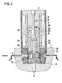
- Figure 1 is an axial section of the embodiment.
- Figure 2 is a section along line II-II of Figure 1.
- FIG. 3 is an explanatory diagram.
- Figure 4 is a partial section of the alternative embodiment.
- the valve comprises a body 1, with two passages 2 and 3 for the inlet and outlet of the fluid to be checked and vice versa, because the valve is designed to control the passage of the fluid in one direction and in the other.
- the body 1 carries a casing 4 made of ferromagnetic material which contains an electric coil 5 carried by a body 6, the internal recess of which constitutes a cylindrical bore containing a fixed ferromagnetic core 7 and a movable ferromagnetic core 8.
- a cylindrical part 9 is forced into the lower end of the cylindrical bore and extends as far as the radial passage 3.
- This part 9 is shaped to provide between it and the bore an annular space 10 in which can s engaging a skirt 11 constituting the lower part of the movable core 8.
- the latter has a longitudinal passage 12 in which is housed a coil spring 13, one end of which bears against a pellet 14 forced into the core 8, its other end s 'pressing against the head 15 of a rod 16 carried by the fixed core 7.
- the longitudinal passage 12 connects the space 17 between the two magnetic cores and the space 18 between the movable core 8 and the cylindrical part 9.
- the cylindrical part 9 has three vertical bores 19 putting the two passages 2 and 3 into communication when the movable core 8 is attracted towards the fixed core 7.
- a portion 20 of the part 9 constitutes a deflector above the passage 19, so that the fluid passing from the passage 2 towards the passage 3 is directed radially on the lower part of the skirt 11 and consequently does not exert a dynamic thrust on the latter .
- the part 9 is shaped so as to provide an annular groove 21 just below the skirt 11, this groove communicating by a passage 22 with the space 18, which contributes to allow the pressure balances of the fluid to be balanced.
- the two opposite faces of the other of the fixed core and the movable core have two recesses 23 and 24 and two projecting parts 25 and 26 intended to penetrate into said recess, this for the purpose to obtain a magnetic attraction force between the cores which is substantially constant over a major part of the travel of the mobile core 8.
- the depth of one of these recesses 23, respectively 24 is different from that of the 'other, while the heights of the projecting parts 25 and 26 correspond substantially to the respective depths of the recesses, so that at the end of the attraction race of the movable core the two projecting parts 25 and 26 are engaged in the two recesses 23 and 24.
- FIG. 3 represents the magnetic attraction force F as a function of the stroke D of the mobile magnetic core.
- Curve a substantially represents the force due to the magnetic field produced between the protruding part 25 and the recess 23, while curve b corresponds to the force due to the magnetic field rising between the protruding part 26 and the recess 24.
- Curve c shows the addition of the attraction forces along curves a and b and has a portion between points d1 and d2 corresponding to a substantially constant attraction force.
- FIG. 4 shows an alternative embodiment in which the cylindrical part 9 does not have a hole 22, the communication between the annular groove 21 and the space 18 being obtained by holes 27 provided in the skirt 11 ′ which is constituted by an insert on the core 8.
- the sealing of the passage of the fluid is achieved by the external surface of the skirt 11 which bears against the internal surface of the cylindrical bore in which the core 8 moves.
- the skirt 11 is supported by its internal surface against the external surface of the cylindrical part 9.
- projecting parts 25 and 26 could be part of one and respectively of the other of the two cores 7 and 8.
- projecting parts and the recesses do not necessarily have to be of circular section, although in principle it is this form which is most convenient for machining.
Landscapes
- Engineering & Computer Science (AREA)
- General Engineering & Computer Science (AREA)
- Mechanical Engineering (AREA)
- Magnetically Actuated Valves (AREA)
Applications Claiming Priority (2)
| Application Number | Priority Date | Filing Date | Title |
|---|---|---|---|
| CH2376/90A CH683283A5 (fr) | 1990-07-17 | 1990-07-17 | Valve à commande électromagnétique pour le contrôle du passage d'un fluide. |
| CH2376/90 | 1990-07-17 |
Publications (2)
| Publication Number | Publication Date |
|---|---|
| EP0467823A1 true EP0467823A1 (de) | 1992-01-22 |
| EP0467823B1 EP0467823B1 (de) | 1993-10-06 |
Family
ID=4232330
Family Applications (1)
| Application Number | Title | Priority Date | Filing Date |
|---|---|---|---|
| EP91810409A Expired - Lifetime EP0467823B1 (de) | 1990-07-17 | 1991-05-30 | Elektromagnetisches Ventil zur Durchflussregelung |
Country Status (5)
| Country | Link |
|---|---|
| US (1) | US5163654A (de) |
| EP (1) | EP0467823B1 (de) |
| JP (1) | JPH04249684A (de) |
| CH (1) | CH683283A5 (de) |
| DE (1) | DE69100470T2 (de) |
Families Citing this family (6)
| Publication number | Priority date | Publication date | Assignee | Title |
|---|---|---|---|---|
| US5531422A (en) * | 1994-04-12 | 1996-07-02 | Applied Power Inc. | Double latching valve |
| ATE184967T1 (de) * | 1995-02-15 | 1999-10-15 | Denison Hydraulik Gmbh | Direktgesteuertes hydraulisches druckventil |
| US6029703A (en) * | 1998-12-18 | 2000-02-29 | Borg-Warner Automotive, Inc. | Pressure solenoid control valve with flux shunt |
| JP2005325940A (ja) * | 2004-05-14 | 2005-11-24 | Smc Corp | 電磁弁 |
| DE102005020278B4 (de) * | 2005-04-28 | 2007-02-15 | Bosch Rexroth Ag | Elektropneumatisches Patronenventil, insbesondere zum Einsatz als Vorsteuerventil bei einem schmalbauenden Pneumatikventil für eine kompakte Ventileinheit |
| US9052033B2 (en) | 2008-12-22 | 2015-06-09 | Artemis Intelligent Power Limited | Valve assembly |
Citations (5)
| Publication number | Priority date | Publication date | Assignee | Title |
|---|---|---|---|---|
| US3223802A (en) * | 1963-06-14 | 1965-12-14 | Schulz Tool & Mfg Co | Solenoid having a two-piece armature |
| US3235223A (en) * | 1962-10-24 | 1966-02-15 | Wintriss George | Disc valve with magnetic operation |
| EP0128124A2 (de) * | 1984-04-10 | 1984-12-12 | WEBER S.r.l. | Elektromagnetisch gesteuertes Drosselklappenumgehungsventil einer Gemischaufbereitungsvorrichtung für eine Brennkraftmaschine |
| US4504039A (en) * | 1982-03-24 | 1985-03-12 | Aisin Seiki Kabushiki of 1 | Solenoid actuated valve device |
| EP0304186A2 (de) * | 1987-08-18 | 1989-02-22 | Western Atlas International, Inc. | Magnetventil für ein Luftdruckschiessgerät |
Family Cites Families (2)
| Publication number | Priority date | Publication date | Assignee | Title |
|---|---|---|---|---|
| US3588039A (en) * | 1969-09-05 | 1971-06-28 | Bolt Associates Inc | Solenoid valve structures and systems |
| EP0055518B1 (de) * | 1980-12-26 | 1986-02-19 | Hitachi, Ltd. | Magnetventil |
-
1990
- 1990-07-17 CH CH2376/90A patent/CH683283A5/fr not_active IP Right Cessation
-
1991
- 1991-05-30 DE DE91810409T patent/DE69100470T2/de not_active Expired - Fee Related
- 1991-05-30 EP EP91810409A patent/EP0467823B1/de not_active Expired - Lifetime
- 1991-07-09 US US07/727,237 patent/US5163654A/en not_active Expired - Fee Related
- 1991-07-15 JP JP3198242A patent/JPH04249684A/ja active Pending
Patent Citations (5)
| Publication number | Priority date | Publication date | Assignee | Title |
|---|---|---|---|---|
| US3235223A (en) * | 1962-10-24 | 1966-02-15 | Wintriss George | Disc valve with magnetic operation |
| US3223802A (en) * | 1963-06-14 | 1965-12-14 | Schulz Tool & Mfg Co | Solenoid having a two-piece armature |
| US4504039A (en) * | 1982-03-24 | 1985-03-12 | Aisin Seiki Kabushiki of 1 | Solenoid actuated valve device |
| EP0128124A2 (de) * | 1984-04-10 | 1984-12-12 | WEBER S.r.l. | Elektromagnetisch gesteuertes Drosselklappenumgehungsventil einer Gemischaufbereitungsvorrichtung für eine Brennkraftmaschine |
| EP0304186A2 (de) * | 1987-08-18 | 1989-02-22 | Western Atlas International, Inc. | Magnetventil für ein Luftdruckschiessgerät |
Also Published As
| Publication number | Publication date |
|---|---|
| EP0467823B1 (de) | 1993-10-06 |
| DE69100470T2 (de) | 1994-04-14 |
| CH683283A5 (fr) | 1994-02-15 |
| US5163654A (en) | 1992-11-17 |
| DE69100470D1 (de) | 1993-11-11 |
| JPH04249684A (ja) | 1992-09-04 |
Similar Documents
| Publication | Publication Date | Title |
|---|---|---|
| EP0117806B1 (de) | Flüssigkeitsverteiler, insbesondere für Fernsteuerung | |
| CA2318353A1 (fr) | Vanne de reglage de debit | |
| FR2541729A1 (fr) | Soupape a commande electromagnetique | |
| EP0197232A1 (de) | Impulsgesteuertes elektromagnetisches Ventil | |
| FR2674307A1 (fr) | Distributeur de commande de circuit pneumatique. | |
| FR2689599A1 (fr) | Distributeur à commande électromagnétique, à trois voies et trois positions. | |
| FR2731261A1 (fr) | Vanne de regulation pour installation hydraulique fonctionnant a l'eau | |
| FR2817605A1 (fr) | Electrovanne proportionnelle pour circuit de liquide de refroidissement de moteur | |
| FR2624488A1 (fr) | Sas a roue cellulaire | |
| EP0467823B1 (de) | Elektromagnetisches Ventil zur Durchflussregelung | |
| CH652803A5 (fr) | Injecteur de combustible et moteur a combustion interne equipe dudit injecteur. | |
| FR2973077A1 (fr) | Regulateur de pression comportant un moteur | |
| FR2479354A1 (fr) | Valve pneumatique regulatrice de pression et de decharge, notamment pour la commande d'un verin pneumatique | |
| CH665264A5 (fr) | Electrovalve a plusieurs debits. | |
| FR2468812A1 (fr) | Soupape de distribution avec dispositif de manoeuvre electromagnetique | |
| EP0947754B1 (de) | Impulsgesteuertes, elektromagnetisches Hydraulikventil | |
| FR2863671A1 (fr) | Dispositif de regulation de pression pour appareil hydraulique a percussion | |
| EP3204631A1 (de) | Kraftstoffeinspritzer | |
| EP3276200A1 (de) | Hydraulische schwingungsdämpfende vorrichtung | |
| EP0802327A1 (de) | Zahnradpumpe | |
| FR2548734A1 (fr) | Injecteur de carburant | |
| FR2504609A1 (fr) | Palette destinee a equiper un dispositif hydraulique rotatif | |
| FR2668238A3 (fr) | Reducteur de pression avec valve inclinee. | |
| CH508159A (fr) | Valve pour fluide | |
| CH637761A5 (fr) | Ensemble constitue par un projectile et le dispositif de lancement de ce projectile. |
Legal Events
| Date | Code | Title | Description |
|---|---|---|---|
| PUAI | Public reference made under article 153(3) epc to a published international application that has entered the european phase |
Free format text: ORIGINAL CODE: 0009012 |
|
| AK | Designated contracting states |
Kind code of ref document: A1 Designated state(s): DE FR GB IT NL SE |
|
| 17P | Request for examination filed |
Effective date: 19920203 |
|
| 17Q | First examination report despatched |
Effective date: 19920702 |
|
| GRAA | (expected) grant |
Free format text: ORIGINAL CODE: 0009210 |
|
| AK | Designated contracting states |
Kind code of ref document: B1 Designated state(s): DE FR GB IT NL SE |
|
| REF | Corresponds to: |
Ref document number: 69100470 Country of ref document: DE Date of ref document: 19931111 |
|
| GBT | Gb: translation of ep patent filed (gb section 77(6)(a)/1977) |
Effective date: 19931115 |
|
| ITF | It: translation for a ep patent filed | ||
| PLBE | No opposition filed within time limit |
Free format text: ORIGINAL CODE: 0009261 |
|
| 26N | No opposition filed | ||
| EAL | Se: european patent in force in sweden |
Ref document number: 91810409.2 |
|
| PGFP | Annual fee paid to national office [announced via postgrant information from national office to epo] |
Ref country code: FR Payment date: 19970418 Year of fee payment: 7 |
|
| PGFP | Annual fee paid to national office [announced via postgrant information from national office to epo] |
Ref country code: GB Payment date: 19970422 Year of fee payment: 7 |
|
| PGFP | Annual fee paid to national office [announced via postgrant information from national office to epo] |
Ref country code: DE Payment date: 19970513 Year of fee payment: 7 |
|
| PGFP | Annual fee paid to national office [announced via postgrant information from national office to epo] |
Ref country code: SE Payment date: 19970520 Year of fee payment: 7 |
|
| PGFP | Annual fee paid to national office [announced via postgrant information from national office to epo] |
Ref country code: NL Payment date: 19970530 Year of fee payment: 7 |
|
| PG25 | Lapsed in a contracting state [announced via postgrant information from national office to epo] |
Ref country code: GB Free format text: LAPSE BECAUSE OF NON-PAYMENT OF DUE FEES Effective date: 19980530 |
|
| PG25 | Lapsed in a contracting state [announced via postgrant information from national office to epo] |
Ref country code: SE Free format text: LAPSE BECAUSE OF NON-PAYMENT OF DUE FEES Effective date: 19980531 Ref country code: FR Free format text: LAPSE BECAUSE OF NON-PAYMENT OF DUE FEES Effective date: 19980531 |
|
| PG25 | Lapsed in a contracting state [announced via postgrant information from national office to epo] |
Ref country code: NL Free format text: LAPSE BECAUSE OF NON-PAYMENT OF DUE FEES Effective date: 19981201 |
|
| GBPC | Gb: european patent ceased through non-payment of renewal fee |
Effective date: 19980530 |
|
| EUG | Se: european patent has lapsed |
Ref document number: 91810409.2 |
|
| NLV4 | Nl: lapsed or anulled due to non-payment of the annual fee |
Effective date: 19981201 |
|
| PG25 | Lapsed in a contracting state [announced via postgrant information from national office to epo] |
Ref country code: DE Free format text: LAPSE BECAUSE OF NON-PAYMENT OF DUE FEES Effective date: 19990302 |
|
| REG | Reference to a national code |
Ref country code: FR Ref legal event code: ST |
|
| PG25 | Lapsed in a contracting state [announced via postgrant information from national office to epo] |
Ref country code: IT Free format text: LAPSE BECAUSE OF NON-PAYMENT OF DUE FEES Effective date: 20050530 |