EP0467898B1 - Four a vide - Google Patents
Four a vide Download PDFInfo
- Publication number
- EP0467898B1 EP0467898B1 EP90904906A EP90904906A EP0467898B1 EP 0467898 B1 EP0467898 B1 EP 0467898B1 EP 90904906 A EP90904906 A EP 90904906A EP 90904906 A EP90904906 A EP 90904906A EP 0467898 B1 EP0467898 B1 EP 0467898B1
- Authority
- EP
- European Patent Office
- Prior art keywords
- furnace
- articles
- heating elements
- housing
- longitudinal dimension
- Prior art date
- Legal status (The legal status is an assumption and is not a legal conclusion. Google has not performed a legal analysis and makes no representation as to the accuracy of the status listed.)
- Expired - Lifetime
Links
Images
Classifications
-
- F—MECHANICAL ENGINEERING; LIGHTING; HEATING; WEAPONS; BLASTING
- F27—FURNACES; KILNS; OVENS; RETORTS
- F27D—DETAILS OR ACCESSORIES OF FURNACES, KILNS, OVENS OR RETORTS, IN SO FAR AS THEY ARE OF KINDS OCCURRING IN MORE THAN ONE KIND OF FURNACE
- F27D11/00—Arrangement of elements for electric heating in or on furnaces
- F27D11/02—Ohmic resistance heating
-
- C—CHEMISTRY; METALLURGY
- C21—METALLURGY OF IRON
- C21D—MODIFYING THE PHYSICAL STRUCTURE OF FERROUS METALS; GENERAL DEVICES FOR HEAT TREATMENT OF FERROUS OR NON-FERROUS METALS OR ALLOYS; MAKING METAL MALLEABLE, e.g. BY DECARBURISATION OR TEMPERING
- C21D9/00—Heat treatment, e.g. annealing, hardening, quenching or tempering, adapted for particular articles; Furnaces therefor
- C21D9/22—Heat treatment, e.g. annealing, hardening, quenching or tempering, adapted for particular articles; Furnaces therefor for drills; for milling cutters; for machine cutting tools
-
- H—ELECTRICITY
- H05—ELECTRIC TECHNIQUES NOT OTHERWISE PROVIDED FOR
- H05B—ELECTRIC HEATING; ELECTRIC LIGHT SOURCES NOT OTHERWISE PROVIDED FOR; CIRCUIT ARRANGEMENTS FOR ELECTRIC LIGHT SOURCES, IN GENERAL
- H05B3/00—Ohmic-resistance heating
- H05B3/62—Heating elements specially adapted for furnaces
- H05B3/64—Heating elements specially adapted for furnaces using ribbon, rod, or wire heater
Definitions
- the present invention relates to an electrically heated vacuum furnaces for heat treating metallic articles
- a pressure vessel housing said housing having a longitudinal dimension; holding means for positioning the metallic articles to be heat treated in an arrangement parallel to the longitudinal dimension of said housing; and a plurality of heating elements in said housing, said heating elements being spaced apart in a first direction normal to the longitudinal dimension of said housing and lying parallel to said longitudinal dimension, said heating elements extending in a second direction normal to said longitudinal dimension and said first direction to have sides lying parallel to said longitudinal dimension, said heating elements being interleaved with the articles positioned by said holding means.
- Vacuum furnaces have a pressure vessel inside which are arranged insulating elements to minimise heat transfer to the walls of the pressure vessel in order to protect the integrity of the vacuum under which the vessel operates in use.
- a vacuum furnace for heat treatment is known with a furnace chamber and with two rows of electrical heating elements disposed within the furnace chamber along opposite sides thereof.
- the heating elements are formed as flat plates which are disposed quite close to the parallel side walls of the furnace chamber and therefore they apply radiant heat not only directly to the workpieces which are located in the centre of the furnace chamber between the two rows, but also to the inner furnace walls.
- a similar furnace using stick-like electrical heating elements is known from US-A 4,398,702.
- an electrical heated vacuum furnace according to the invention includes the features set out in the characterising part of claim 1.
- the furnace may include a plurality of shield sections adjustably disposed within the furnace in shielding relationship to selected parts of articles to be treated in the furnace, whereby differential heating of portions of the articles can be achieved.
- the furnace may include a plurality of shield sections adjustably disposed within the furnace in shielding relationship to selected ones of plural layers of components, whereby the articles in different layers in the furnace can still be heated and cooled uniformly.
- a further advantage of the invention is that a reduction in temperature of the heating elements in comparison with known techniques may be achieved, by spreading the sources of heat radiation throughout the furnace rather than locating them solely around the periphery.
- the technique also obviates the need for complex and costly gas circulation systems, which are needed to improve heat-up times and temperature uniformities in the low temperature (black radiation) ranges, by enabling close spacing of the workpieces from the heating elements.
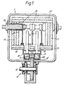
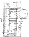
- the furnace of the first example is shown diagrammatically in Figures 1 and 2 for simplicity.
- the furnace has an elongate, tubular form, housing 1 which comprises a pressure vessel so that the furnace can be evacuated in use. Since the evacuation of the furnace forms no part of this invention, elements relating thereto are neither described nor shown in the drawings.
- the furnace has a front opening 2 and a rear opening 3 through which articles to be heat treated in the furnace can be loaded into and passed out of the furnace respectively.
- Air-tight doors (not shown) are provided to seal the ends of the pressure vessel.
- a loading chamber and a cooling chamber (not shown) may be located immediately in front of and behind the furnace respectively, communicating with the interior of the furnace through the openings 2,3.
- the furnace includes a mechanism 4 by means of which plural workpieces can be loaded into the furnace and removed therefrom quickly and efficiently.
- this mechanism comprises a rack and pinion drive indicated schematically, the pinion 5 having a suitable drive mechanism 6 and engaging, through the wall of the furnace, a rack 7 attached to the underside of a workpiece support 8.
- the workpiece support is preferably formed of an insulating material and is supported on elongate graphite blocks 9 which slide on graphite cards 9' and act both as bearings and to reduce transmission of heat to the rack and pinion mechanism, the graphite blocks and cards being located in an elongate guide 18.
- the workpiece support 8 is shown supporting a row of elongate metallic workpieces 10, in the present case drill bits or drill blanks, which are to be hardened in the furnace.
- the furnace of the present invention has an array of heating elements comprising three elongate belt-like sintered resistance heating elements 13 disposed parallel to the longitudinal centreline of the furnace and closely adjacent to the bits 10 in use.
- Each of the resistance elements 13 is supported at one end from the power feed-through 14 and the other end by an earthed support, the heating elements being disposed towards the top of the bits 10 in order to provide direct heat radiation to the tips 11 of the bits 10.
- a thermally insulating shielding element 15 is provided on each side of the row of bits, a small gap 16 being left between them for the passage of the bit.
- Similar heat shielding elements 17 and 17' are disposed around the sides and top of the furnace in order to shield the pressure vessel wall from direct heat from the heating elements 13.
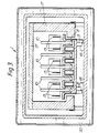
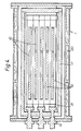
- FIG. 3 A second example of a vacuum furnace according to the present invention is shown in Figures 3 and 4.
- the same reference numerals are used for those features in Figures 3 and 4 which correspond to features shown in Figures 1 and 2.
- the housing 1 has a water jacket 20 surrounding it (Figure 3 only).
- the furnace has side 17 and top 17' heat shielding elements and a workpiece support 8 of insulating material supported on graphite blocks 9 whch slide on guides 18.
- six heating elements 13 are evenly distributed across the width of the furnace so that up to five rows of workpieces 10 can be accommodated as shown.
- Power feed-through 14 to the elements 13 in this example is from one end of the furnace.
- power fed to the heating elements may be individually controlled and matched to the particular process requirements to provide balanced heating of the hot zone within the furnace in order to maximise uniformity.
Landscapes
- Engineering & Computer Science (AREA)
- Chemical & Material Sciences (AREA)
- Mechanical Engineering (AREA)
- Organic Chemistry (AREA)
- Thermal Sciences (AREA)
- Materials Engineering (AREA)
- Metallurgy (AREA)
- Physics & Mathematics (AREA)
- General Engineering & Computer Science (AREA)
- Crystallography & Structural Chemistry (AREA)
- Furnace Details (AREA)
- Tunnel Furnaces (AREA)
- Control And Other Processes For Unpacking Of Materials (AREA)
- Cookers (AREA)
- Telephone Function (AREA)
- Muffle Furnaces And Rotary Kilns (AREA)
- Crystals, And After-Treatments Of Crystals (AREA)
- Secondary Cells (AREA)
- Physical Vapour Deposition (AREA)
Claims (6)
- Four sous vide chauffé électriquement pour traiter thermiquement des articles métalliques, comprenant :un logement de cuve sous pression (1), ledit logement possédant une dimension longitudinale ;des moyens de maintien (8) pour positionner les articles métalliques (10) devant être traités thermiquement selon un agencement parallèle à la dimension longitudinale dudit logement ; et une pluralité d'éléments de chauffage (13) dans ledit logement, lesdits éléments de chauffage (13) étant écartés selon une première direction normale à la dimension longitudinale dudit logement et reposant parallèlement à ladite dimension longitudinale, lesdits éléments de chauffage (13) s'étendant selon une seconde direction normale à ladite dimension longitudinale et à ladite première direction afin d'avoir des côtés reposant parallèlement à ladite dimension longitudinale, lesdits éléments de chauffage (13) étant intercalés avec les articles positionnés par lesdits moyens de maintien (8), caractérisé en ce que les moyens de maintien positionnent lesdits articles métalliques (10) devant être traités thermiquement dans ledit logement (1) selon au moins une paire de rangées, en ce que les éléments de chauffage (13) comprennent des éléments de chauffage à résistance, allongés et de type courroie s'étendant longitudinalement au logement et en ce qu'au moins un desdits éléments de chauffage (13) applique une chaleur de rayonnement sur les articles (10) disposés selon des rangées, des deux côtés dudit élément de chauffage de traiter thermiquement ces articles (10).
- Four selon la revendication 1, caractérisé par un mécanisme d'alimentation possédant un transporteur de pièces (8) mobile le long de la longueur du four afin d'amener des pièces dans le, et en dehors du, four.
- Four selon la revendication 2, caractérisé par le mécanisme d'alimentation comprenant un mécanisme de crémaillère (5, 6, 7).
- Four selon la revendication 2 ou 3, caractérisé par le mécanisme d'alimentation comprenant une pluralité de blocs de paliers en graphite (9, 9') sur lesquels le transporteur (8) est disposé pour coulisser et qui réduit la transmission de chaleur provenant du four en utilisation.
- Four selon l'une quelconque des revendications 1 à 4, caractérisé par une pluralité de sections de protection (15) disposées de façon réglable à l'intérieur du four en relation de protection avec des parties sélectionnées des articles (10) devant être traités dans le four, si bien qu'un chauffage différentiel des parties des articles (10) peut être obtenu.
- Four selon l'une quelconque des revendications 1 à 4, caractérisé par une pluralité de sections de protection (15) disposées de façon réglable à l'intérieur du four en relation de protection avec celles sélectionnées de plusieurs couches de composants, si bien que les articles en différentes couches dans le four peuvent encore être chauffés et refroidis uniformément.
Applications Claiming Priority (3)
| Application Number | Priority Date | Filing Date | Title |
|---|---|---|---|
| GB898907994A GB8907994D0 (en) | 1989-04-10 | 1989-04-10 | Vacuum furnace |
| GB8907994 | 1989-04-10 | ||
| PCT/GB1990/000468 WO1990012266A1 (fr) | 1989-04-10 | 1990-03-29 | Four a vide |
Publications (3)
| Publication Number | Publication Date |
|---|---|
| EP0467898A1 EP0467898A1 (fr) | 1992-01-29 |
| EP0467898B1 true EP0467898B1 (fr) | 1996-06-05 |
| EP0467898B2 EP0467898B2 (fr) | 2001-07-11 |
Family
ID=10654725
Family Applications (1)
| Application Number | Title | Priority Date | Filing Date |
|---|---|---|---|
| EP90904906A Expired - Lifetime EP0467898B2 (fr) | 1989-04-10 | 1990-03-29 | Four a vide |
Country Status (7)
| Country | Link |
|---|---|
| US (1) | US5251231A (fr) |
| EP (1) | EP0467898B2 (fr) |
| AT (1) | ATE139025T1 (fr) |
| DE (1) | DE69027317T3 (fr) |
| ES (1) | ES2087909T5 (fr) |
| GB (1) | GB8907994D0 (fr) |
| WO (1) | WO1990012266A1 (fr) |
Families Citing this family (6)
| Publication number | Priority date | Publication date | Assignee | Title |
|---|---|---|---|---|
| JP3398341B2 (ja) * | 1999-02-16 | 2003-04-21 | 安斎 節 | 電気抵抗式溶融炉 |
| GB0018616D0 (en) | 2000-07-28 | 2000-09-13 | Dormer Tools Sheffield Ltd | Method and means for heat treating cutting tools |
| US6349108B1 (en) | 2001-03-08 | 2002-02-19 | Pv/T, Inc. | High temperature vacuum furnace |
| EP1318696B1 (fr) * | 2001-11-28 | 2005-06-15 | Ipsen International GmbH | Procédé de chauffage électrique d'un four pour le traitment thermique de pièces métalliques |
| EP2610354A1 (fr) * | 2011-12-29 | 2013-07-03 | Ipsen, Inc. | Compensation d'agencement dýéléments chauffants pour four de traitement de chaleur pour un four de traitement thermique sous vide |
| CA3177506A1 (fr) | 2012-06-20 | 2013-12-20 | Kelvin Storage Canada Inc. | Systeme de transport d'energie renouvelable mondial |
Family Cites Families (17)
| Publication number | Priority date | Publication date | Assignee | Title |
|---|---|---|---|---|
| US2678958A (en) * | 1950-12-08 | 1954-05-18 | Hintenberger Karl | Electric oven for the burning of ceramic articles |
| CH298669A (de) * | 1952-01-31 | 1954-05-15 | Alois Dr Vogt | Elektrisch beheizter Hochtemperaturofen. |
| DE1783069B1 (de) * | 1968-09-27 | 1971-08-05 | Degussa | Durchstossofen mit graphitstabheizung |
| FR1587773A (fr) * | 1968-09-30 | 1970-03-27 | ||
| FR2067967A5 (fr) * | 1969-11-24 | 1971-08-20 | Anvar | |
| US3610391A (en) * | 1970-03-20 | 1971-10-05 | Btu Eng Corp | Furnace conveyor system |
| SE349858B (fr) * | 1970-10-27 | 1972-10-09 | Asea Ab | |
| GB1510702A (en) * | 1975-03-25 | 1978-05-17 | Secr Defence | Electric furnaces |
| SE389957B (sv) * | 1975-04-25 | 1976-11-22 | Asea Ab | Cylinderformad langstreckt ugn for behandling av material vid hog temperatur i en gasatmosfer under hogt tryck |
| FR2453377A1 (fr) * | 1979-04-04 | 1980-10-31 | Dupeux Ets M | Four electrique destine a la cuisson d'articles ceramiques |
| FR2487491A1 (fr) * | 1980-07-25 | 1982-01-29 | Bmi | Four a passage sous vide pour le traitement thermique ou thermochimique en continu de metaux |
| US4347431A (en) * | 1980-07-25 | 1982-08-31 | Bell Telephone Laboratories, Inc. | Diffusion furnace |
| DE3111218A1 (de) * | 1981-03-21 | 1982-12-16 | Ipsen Industries International Gmbh, 4190 Kleve | Ofen zur waermebehandlung von bohrern |
| US4416623A (en) * | 1982-02-01 | 1983-11-22 | Kanto Yakin Kogyo Kabushiki Kaisha | Muffle furnace |
| US4398702A (en) * | 1982-03-22 | 1983-08-16 | Ultra-Temp Corporation | Metallurgical furnace |
| US4569661A (en) * | 1984-09-04 | 1986-02-11 | General Electric Company | Furnace construction |
| DE3726134A1 (de) * | 1987-08-06 | 1989-02-23 | Degussa | Halterung zur partiellen waermebehandlung von werkzeugen in oefen |
-
1989
- 1989-04-10 GB GB898907994A patent/GB8907994D0/en active Pending
-
1990
- 1990-03-29 DE DE69027317T patent/DE69027317T3/de not_active Expired - Fee Related
- 1990-03-29 EP EP90904906A patent/EP0467898B2/fr not_active Expired - Lifetime
- 1990-03-29 AT AT90904906T patent/ATE139025T1/de not_active IP Right Cessation
- 1990-03-29 ES ES90904906T patent/ES2087909T5/es not_active Expired - Lifetime
- 1990-03-29 WO PCT/GB1990/000468 patent/WO1990012266A1/fr not_active Ceased
- 1990-03-29 US US07/777,338 patent/US5251231A/en not_active Expired - Lifetime
Also Published As
| Publication number | Publication date |
|---|---|
| ATE139025T1 (de) | 1996-06-15 |
| WO1990012266A1 (fr) | 1990-10-18 |
| ES2087909T5 (es) | 2001-11-16 |
| EP0467898B2 (fr) | 2001-07-11 |
| DE69027317T2 (de) | 1996-10-10 |
| ES2087909T3 (es) | 1996-08-01 |
| US5251231A (en) | 1993-10-05 |
| EP0467898A1 (fr) | 1992-01-29 |
| DE69027317T3 (de) | 2003-03-13 |
| DE69027317D1 (de) | 1996-07-11 |
| GB8907994D0 (en) | 1989-05-24 |
Similar Documents
| Publication | Publication Date | Title |
|---|---|---|
| CA1313043C (fr) | Etuve a vide pour le traitement thermique de pieces metalliques | |
| US3609295A (en) | Heating apparatus with workpiece carriers | |
| EP0467898B2 (fr) | Four a vide | |
| US4441698A (en) | Furnace for the heat treatment of drills | |
| CS274632B2 (en) | Method of metallic workpieces thermal treatment | |
| GB1492585A (en) | Microwave fritting of ceramic products | |
| US4455177A (en) | Method and apparatus for chemical heat treatment of steel parts utilizing a continuous electric furnace | |
| JP2004526649A5 (fr) | ||
| KR100469522B1 (ko) | 열처리 장치 | |
| CN100507026C (zh) | 热处理切削工具的方法和设备 | |
| US6349108B1 (en) | High temperature vacuum furnace | |
| AU2001272673A1 (en) | Method and means for heat treating cutting tools | |
| GB1394200A (fr) | ||
| JP7792925B2 (ja) | 熱処理炉 | |
| JPS55117593A (en) | Continuous drying or baking method of covered electrode and drying or baking furnace used for this | |
| US5097114A (en) | Low-voltage heating device | |
| KR100418492B1 (ko) | 시트형 피가열체 열처리장치 및 그 열처리방법 | |
| ITMC990091A1 (it) | Procedimento di riscaldo continuo dei semilavorati metallici tramite passaggio diretto di corrente elettrica entro il semilavorato da riscal | |
| KR830002717Y1 (ko) | 열처리 로(熱處理爐) | |
| RU2140392C1 (ru) | Способ и устройство для графитации углеродных заготовок | |
| DE2722545A1 (de) | Vorrichtung zum heizen | |
| JPS575825A (en) | Heat treatment furnace for long material | |
| JPS60131914A (ja) | バツチ式熱処理装置 | |
| Ritter et al. | Apparatus for Heat-Treating(in Particular Annealing) a Continuously Moving Metal Wire | |
| JPS60255917A (ja) | 連続熱処理装置 |
Legal Events
| Date | Code | Title | Description |
|---|---|---|---|
| PUAI | Public reference made under article 153(3) epc to a published international application that has entered the european phase |
Free format text: ORIGINAL CODE: 0009012 |
|
| 17P | Request for examination filed |
Effective date: 19911112 |
|
| AK | Designated contracting states |
Kind code of ref document: A1 Designated state(s): AT BE CH DE DK ES FR GB IT LI LU NL SE |
|
| RIN1 | Information on inventor provided before grant (corrected) |
Inventor name: ELLIS, MICHAEL GEORGE Inventor name: CROKER, MICHAEL NORMAN |
|
| RBV | Designated contracting states (corrected) |
Designated state(s): AT CH DE ES FR GB IT LI SE |
|
| RAP1 | Party data changed (applicant data changed or rights of an application transferred) |
Owner name: IPSEN INDUSTRIES INTERNATIONAL GESELLSCHAFT MIT BE |
|
| 17Q | First examination report despatched |
Effective date: 19930722 |
|
| GRAA | (expected) grant |
Free format text: ORIGINAL CODE: 0009210 |
|
| AK | Designated contracting states |
Kind code of ref document: B1 Designated state(s): AT CH DE ES FR GB IT LI SE |
|
| REF | Corresponds to: |
Ref document number: 139025 Country of ref document: AT Date of ref document: 19960615 Kind code of ref document: T |
|
| ET | Fr: translation filed | ||
| REG | Reference to a national code |
Ref country code: ES Ref legal event code: BA2A Ref document number: 2087909 Country of ref document: ES Kind code of ref document: T3 |
|
| REF | Corresponds to: |
Ref document number: 69027317 Country of ref document: DE Date of ref document: 19960711 |
|
| REG | Reference to a national code |
Ref country code: ES Ref legal event code: FG2A Ref document number: 2087909 Country of ref document: ES Kind code of ref document: T3 |
|
| ITF | It: translation for a ep patent filed | ||
| PLBI | Opposition filed |
Free format text: ORIGINAL CODE: 0009260 |
|
| PLBF | Reply of patent proprietor to notice(s) of opposition |
Free format text: ORIGINAL CODE: EPIDOS OBSO |
|
| 26 | Opposition filed |
Opponent name: ALD VACUUM TECHNOLOGIES, PATENTABTEILUNG Effective date: 19970305 |
|
| PLBF | Reply of patent proprietor to notice(s) of opposition |
Free format text: ORIGINAL CODE: EPIDOS OBSO |
|
| PLBF | Reply of patent proprietor to notice(s) of opposition |
Free format text: ORIGINAL CODE: EPIDOS OBSO |
|
| PLAW | Interlocutory decision in opposition |
Free format text: ORIGINAL CODE: EPIDOS IDOP |
|
| PLAW | Interlocutory decision in opposition |
Free format text: ORIGINAL CODE: EPIDOS IDOP |
|
| PLAW | Interlocutory decision in opposition |
Free format text: ORIGINAL CODE: EPIDOS IDOP |
|
| PLBQ | Unpublished change to opponent data |
Free format text: ORIGINAL CODE: EPIDOS OPPO |
|
| PLAB | Opposition data, opponent's data or that of the opponent's representative modified |
Free format text: ORIGINAL CODE: 0009299OPPO |
|
| R26 | Opposition filed (corrected) |
Opponent name: ALD VACUUM TECHNOLOGIES, PATENTABTEILUNG Effective date: 19970305 |
|
| PLAW | Interlocutory decision in opposition |
Free format text: ORIGINAL CODE: EPIDOS IDOP |
|
| PUAH | Patent maintained in amended form |
Free format text: ORIGINAL CODE: 0009272 |
|
| STAA | Information on the status of an ep patent application or granted ep patent |
Free format text: STATUS: PATENT MAINTAINED AS AMENDED |
|
| 27A | Patent maintained in amended form |
Effective date: 20010711 |
|
| AK | Designated contracting states |
Kind code of ref document: B2 Designated state(s): AT CH DE ES FR GB IT LI SE |
|
| REG | Reference to a national code |
Ref country code: CH Ref legal event code: AEN Free format text: AUFRECHTERHALTUNG DES PATENTES IN GEAENDERTER FORM |
|
| ET3 | Fr: translation filed ** decision concerning opposition | ||
| ITF | It: translation for a ep patent filed | ||
| PG25 | Lapsed in a contracting state [announced via postgrant information from national office to epo] |
Ref country code: DE Free format text: LAPSE BECAUSE OF FAILURE TO SUBMIT A TRANSLATION OF THE DESCRIPTION OR TO PAY THE FEE WITHIN THE PRESCRIBED TIME-LIMIT Effective date: 20011012 |
|
| REG | Reference to a national code |
Ref country code: ES Ref legal event code: DC2A Kind code of ref document: T5 Effective date: 20011001 |
|
| REG | Reference to a national code |
Ref country code: GB Ref legal event code: IF02 |
|
| REG | Reference to a national code |
Ref country code: DE Ref legal event code: 8570 |
|
| PGFP | Annual fee paid to national office [announced via postgrant information from national office to epo] |
Ref country code: CH Payment date: 20040302 Year of fee payment: 15 |
|
| PGFP | Annual fee paid to national office [announced via postgrant information from national office to epo] |
Ref country code: AT Payment date: 20040303 Year of fee payment: 15 |
|
| PGFP | Annual fee paid to national office [announced via postgrant information from national office to epo] |
Ref country code: ES Payment date: 20040319 Year of fee payment: 15 |
|
| PGFP | Annual fee paid to national office [announced via postgrant information from national office to epo] |
Ref country code: SE Payment date: 20050310 Year of fee payment: 16 |
|
| PGFP | Annual fee paid to national office [announced via postgrant information from national office to epo] |
Ref country code: FR Payment date: 20050311 Year of fee payment: 16 |
|
| PGFP | Annual fee paid to national office [announced via postgrant information from national office to epo] |
Ref country code: GB Payment date: 20050322 Year of fee payment: 16 |
|
| PG25 | Lapsed in a contracting state [announced via postgrant information from national office to epo] |
Ref country code: IT Free format text: LAPSE BECAUSE OF NON-PAYMENT OF DUE FEES;WARNING: LAPSES OF ITALIAN PATENTS WITH EFFECTIVE DATE BEFORE 2007 MAY HAVE OCCURRED AT ANY TIME BEFORE 2007. THE CORRECT EFFECTIVE DATE MAY BE DIFFERENT FROM THE ONE RECORDED. Effective date: 20050329 Ref country code: AT Free format text: LAPSE BECAUSE OF NON-PAYMENT OF DUE FEES Effective date: 20050329 |
|
| PG25 | Lapsed in a contracting state [announced via postgrant information from national office to epo] |
Ref country code: ES Free format text: LAPSE BECAUSE OF NON-PAYMENT OF DUE FEES Effective date: 20050330 |
|
| PG25 | Lapsed in a contracting state [announced via postgrant information from national office to epo] |
Ref country code: LI Free format text: LAPSE BECAUSE OF NON-PAYMENT OF DUE FEES Effective date: 20050331 Ref country code: CH Free format text: LAPSE BECAUSE OF NON-PAYMENT OF DUE FEES Effective date: 20050331 |
|
| PGFP | Annual fee paid to national office [announced via postgrant information from national office to epo] |
Ref country code: DE Payment date: 20050510 Year of fee payment: 16 |
|
| REG | Reference to a national code |
Ref country code: CH Ref legal event code: PL |
|
| PG25 | Lapsed in a contracting state [announced via postgrant information from national office to epo] |
Ref country code: GB Free format text: LAPSE BECAUSE OF NON-PAYMENT OF DUE FEES Effective date: 20060329 |
|
| PG25 | Lapsed in a contracting state [announced via postgrant information from national office to epo] |
Ref country code: SE Free format text: LAPSE BECAUSE OF NON-PAYMENT OF DUE FEES Effective date: 20060330 |
|
| REG | Reference to a national code |
Ref country code: ES Ref legal event code: FD2A Effective date: 20050330 |
|
| EUG | Se: european patent has lapsed | ||
| GBPC | Gb: european patent ceased through non-payment of renewal fee |
Effective date: 20060329 |
|
| REG | Reference to a national code |
Ref country code: FR Ref legal event code: ST Effective date: 20061130 |
|
| PG25 | Lapsed in a contracting state [announced via postgrant information from national office to epo] |
Ref country code: FR Free format text: LAPSE BECAUSE OF NON-PAYMENT OF DUE FEES Effective date: 20060331 |