EP0468169A1 - Méthode et appareil pour évaluer les données mémorisées pour commander un robot en particulier pour la fabrication de chaussures - Google Patents
Méthode et appareil pour évaluer les données mémorisées pour commander un robot en particulier pour la fabrication de chaussures Download PDFInfo
- Publication number
- EP0468169A1 EP0468169A1 EP91109078A EP91109078A EP0468169A1 EP 0468169 A1 EP0468169 A1 EP 0468169A1 EP 91109078 A EP91109078 A EP 91109078A EP 91109078 A EP91109078 A EP 91109078A EP 0468169 A1 EP0468169 A1 EP 0468169A1
- Authority
- EP
- European Patent Office
- Prior art keywords
- intersection
- tool
- robot
- sectional area
- cross
- Prior art date
- Legal status (The legal status is an assumption and is not a legal conclusion. Google has not performed a legal analysis and makes no representation as to the accuracy of the status listed.)
- Granted
Links
Images
Classifications
-
- G—PHYSICS
- G05—CONTROLLING; REGULATING
- G05B—CONTROL OR REGULATING SYSTEMS IN GENERAL; FUNCTIONAL ELEMENTS OF SUCH SYSTEMS; MONITORING OR TESTING ARRANGEMENTS FOR SUCH SYSTEMS OR ELEMENTS
- G05B19/00—Program-control systems
- G05B19/02—Program-control systems electric
- G05B19/42—Recording and playback systems, i.e. in which the program is recorded from a cycle of operations, e.g. the cycle of operations being manually controlled, after which this record is played back on the same machine
- G05B19/4202—Recording and playback systems, i.e. in which the program is recorded from a cycle of operations, e.g. the cycle of operations being manually controlled, after which this record is played back on the same machine preparation of the program medium using a drawing, a model
- G05B19/4207—Recording and playback systems, i.e. in which the program is recorded from a cycle of operations, e.g. the cycle of operations being manually controlled, after which this record is played back on the same machine preparation of the program medium using a drawing, a model in which a model is traced or scanned and corresponding data recorded
-
- A—HUMAN NECESSITIES
- A43—FOOTWEAR
- A43D—MACHINES, TOOLS, EQUIPMENT OR METHODS FOR MANUFACTURING OR REPAIRING FOOTWEAR
- A43D1/00—Foot or last measuring devices; Measuring devices for shoe parts
- A43D1/04—Last-measuring devices
-
- A—HUMAN NECESSITIES
- A43—FOOTWEAR
- A43D—MACHINES, TOOLS, EQUIPMENT OR METHODS FOR MANUFACTURING OR REPAIRING FOOTWEAR
- A43D119/00—Driving or controlling mechanisms of shoe machines; Frames for shoe machines
-
- G—PHYSICS
- G05—CONTROLLING; REGULATING
- G05B—CONTROL OR REGULATING SYSTEMS IN GENERAL; FUNCTIONAL ELEMENTS OF SUCH SYSTEMS; MONITORING OR TESTING ARRANGEMENTS FOR SUCH SYSTEMS OR ELEMENTS
- G05B2219/00—Program-control systems
- G05B2219/30—Nc systems
- G05B2219/37—Measurements
- G05B2219/37198—Machine as measuring station, use tool or probe, in process incycle
-
- G—PHYSICS
- G05—CONTROLLING; REGULATING
- G05B—CONTROL OR REGULATING SYSTEMS IN GENERAL; FUNCTIONAL ELEMENTS OF SUCH SYSTEMS; MONITORING OR TESTING ARRANGEMENTS FOR SUCH SYSTEMS OR ELEMENTS
- G05B2219/00—Program-control systems
- G05B2219/30—Nc systems
- G05B2219/45—Nc applications
- G05B2219/45243—Shoe, footwear making
-
- G—PHYSICS
- G05—CONTROLLING; REGULATING
- G05B—CONTROL OR REGULATING SYSTEMS IN GENERAL; FUNCTIONAL ELEMENTS OF SUCH SYSTEMS; MONITORING OR TESTING ARRANGEMENTS FOR SUCH SYSTEMS OR ELEMENTS
- G05B2219/00—Program-control systems
- G05B2219/30—Nc systems
- G05B2219/49—Nc machine tool, till multiple
- G05B2219/49231—Keep tool, probe at constant distance from workpiece surface
Definitions
- the invention relates to a method for determining the data to be stored for the control of a robot, in particular for shoe manufacture, the shoe shafts of which are arranged on the robot arm and which operates on the shoe uppers, and a device for carrying out the method.
- the invention relates not only to the field of shoe manufacture, it can also be used in all technical fields in which contactless scanning is advantageous and on which the determined data is used to control a device whose distance from a workpiece to be machined must be kept constant, such as with flame, water jet and laser cutting devices, the punching and nippling of sheet metal according to contour specifications, etc.
- shoe manufacture is to be understood to mean the molding of shoe soles to shoe uppers, and the gluing of prefabricated shoe soles to shoe uppers.
- the shoe upper which is mounted on a last with two side moldings in the closed position and a base stamp immersed in the side moldings, delimits a mold cavity to which the material for molding the shoe sole is supplied to the shoe upper while simultaneously molding the shoe sole (DE- PS 20 22 118, DE-PS 22 41 493, DE-AS 20 22 118, DE-AS 20 48 596, DE-OS 14 85 978, DD-PS 64 882).
- thermoplastic material is PVC, fully reacted polyurethane etc. granulated, plasticized and injected into the mold cavity via the sprue hole under appropriate pressure.
- mixtures of isocyanate and polyol which react to form polyurethane can also be fed to the mold cavity, the elasticity of which is adjusted by corresponding additional chemical compounds.
- shoe soles are molded onto shoe uppers which have one or more sole layers - outsole and midsole or outsole, midsole and shaft sole.
- Optimal adhesion of a sole requires that a shoe upper in the contact zones or contact areas with the sole be free of surface layers, e.g. free of paint, impurities and the like, and is roughened.
- soles are molded onto shoe uppers in such a way that, in addition to the insole or the floor surface, they overlap the adjoining lateral zone of the shoe upper.
- the invention deals below with, among other things, the roughening of the shoe upper and / or the adhesive application by means of a spray nozzle in this lateral zone which adjoins the insole or floor surface and which extends when the sole is molded up to the sealing edge of the side moldings in the closed position .
- This roughening or spraying with adhesive has hitherto generally been carried out by applying a template to the shoe upper and manually roughening the lateral zone with a milling cutter or by applying adhesive with a suitable device.
- the invention is based on the knowledge that corrections of incorrect data could be carried out most simply if there was no material removal or spraying with adhesive when the data were recorded. This also applies to the other areas of technology mentioned above.
- the invention is therefore based on the object, the method of the type mentioned to be designed in such a way that there is no processing during the recording, so that a correction of incorrectly obtained data is readily possible.
- This object is achieved in that instead of the tool of a device which emits two intersecting light beams, the device is arranged on the robot arm, the axes of the light beams are inclined to one another in such a way that the intersection of the light beams occupies the machining point on the tool, the intersection along the line of the sealing edge is performed, the coordinates of the robot arm moving with the intersection are recorded and stored as data and then, after the device has been replaced by the tool, the robot is controlled with the data.
- the intersection is guided so that its cross-sectional area is essentially constant.
- the constancy of the cross-sectional area is checked visually by the operating personnel in the simplest case.
- the constancy of the cross-sectional area is checked with a video camera.
- a video camera This can be done, for example, in such a way that the recorded image of the cross-sectional area is shown on a display with millimeter grid, so that an enlargement or reduction of the cross-sectional area can be visually recognized by a correspondingly larger or smaller number of the illuminated elementary squares. Accordingly, the image of the cross-sectional area can also be depicted darkly on a light background. Instead of visual observation, the comparison can also be done electronically.
- the images of the cross-sectional area recorded with the video camera are compared with the stored image of a cross-sectional area, with a deviation of the two images by a predetermined amount, the intersection of the two light beams perpendicular to the instantaneous point of impact a movement of the robot arm is postponed.
- the invention is based on the further object of providing an apparatus for carrying out the method.
- the device has two radiation sources each emitting a light beam, the two radiation sources in the device being displaceable relative to one another and pivotable relative to one another.
- the mutual distance between the two radiation sources can be changed by the shift.
- the arrangement of the two radiation sources, which can be pivoted relative to one another makes it easy to move the cross-sectional area of the two light sources to the processing point of the processing devices or tools to be inserted later in the robot arm.
- the two radiation sources are each arranged in a pivoting device and the two pivoting devices can be pivoted with one another such that the intersection of the two light beams and the intersection of the pivot axes of the pivoting devices with the straight line connecting them form an isosceles triangle.
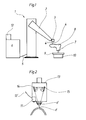
- FIG. 1 A view of the entire device is shown schematically in FIG. 1 with the robot is designated, the arm 2 at the front free end of the device according to the invention for generating the cross-sectional area of the two intersecting beams, which are designated 4 and 4 '.
- the data to be stored are recorded using the known teach-in method, which is generally known and therefore requires no further explanation.
- the robot arm 2 has this device 3 for recording the data to be stored. It is controlled by an operator, not shown, by means of a manual control for the robot and the robot arm, which is also not shown, in such a way that the intersection of the two light beams “migrates” along the line of the sealing edge on the shoe upper, ie that the intersection (light spot) also constant cross section along this working line.
- the shoe uppers 8 listed on a last 7 on transport pallets with a schematically indicated conveyor system 10 can be brought into an always defined and identical position to the robot, so that a clear assignment of the data to be recorded and stored in relation to the working line is ensured, namely during the passage of the light spot or the intersection of the two crossing light beams 4 and 4 '.
- the robot can additionally have a video camera 11, which according to FIG. 2 is integrated in the device 3 and from which a signal line 12 ′ leads to an electronic assembly 12, which on the one hand has a memory for storing a light spot with a predetermined cross section , furthermore has a memory for the current storage of the light spot recorded by the video camera while it is being guided along the work line, a comparison device then also being provided which compares the recorded images with the stored image.
- a video camera 11 which according to FIG. 2 is integrated in the device 3 and from which a signal line 12 ′ leads to an electronic assembly 12, which on the one hand has a memory for storing a light spot with a predetermined cross section , furthermore has a memory for the current storage of the light spot recorded by the video camera while it is being guided along the work line, a comparison device then also being provided which compares the recorded images with the stored image.
- control arm pivots by appropriate control commands in such a way that the cross-sectional area again reaches the predetermined size (setpoint).
- Figure 2 shows schematically the device 3 with the two light beams. It has a housing 13 in which the two light emitters 14 and 15 can be pivoted relative to one another on a rail (optical bench), in such a way that when the one light emitter is pivoted, the other light emitter is automatically pivoted so that the two of the angles enclosed by the rail and the light rays, which are denoted by ⁇ , are always of the same size.
- a rail optical bench
Landscapes
- Physics & Mathematics (AREA)
- General Physics & Mathematics (AREA)
- Engineering & Computer Science (AREA)
- Automation & Control Theory (AREA)
- Manipulator (AREA)
- Footwear And Its Accessory, Manufacturing Method And Apparatuses (AREA)
Applications Claiming Priority (4)
| Application Number | Priority Date | Filing Date | Title |
|---|---|---|---|
| DE4023896 | 1990-07-27 | ||
| DE4023896 | 1990-07-27 | ||
| DE4100806A DE4100806C2 (de) | 1990-07-27 | 1991-01-12 | Verfahren und Vorrichtung zum Bestimmen von Koordinatenwerten zur Steuerung eines Roboters, insbesondere für die Schuhfertigung |
| DE4100806 | 1991-01-12 |
Publications (2)
| Publication Number | Publication Date |
|---|---|
| EP0468169A1 true EP0468169A1 (fr) | 1992-01-29 |
| EP0468169B1 EP0468169B1 (fr) | 1995-08-09 |
Family
ID=25895415
Family Applications (1)
| Application Number | Title | Priority Date | Filing Date |
|---|---|---|---|
| EP19910109078 Expired - Lifetime EP0468169B1 (fr) | 1990-07-27 | 1991-06-04 | Méthode et appareil pour évaluer les données mémorisées pour commander un robot en particulier pour la fabrication de chaussures |
Country Status (3)
| Country | Link |
|---|---|
| EP (1) | EP0468169B1 (fr) |
| DK (1) | DK0468169T3 (fr) |
| ES (1) | ES2077717T3 (fr) |
Cited By (2)
| Publication number | Priority date | Publication date | Assignee | Title |
|---|---|---|---|---|
| WO1999063411A1 (fr) * | 1998-05-30 | 1999-12-09 | Hp-Chemie Research And Development Ltd. | Programmation des coordonnees spatiales de decoupe d'appareils a decouper par jet d'eau |
| WO2001084972A3 (fr) * | 2000-05-05 | 2002-05-16 | Ponfac S A | Equipement d'alignement de chaussures |
Citations (2)
| Publication number | Priority date | Publication date | Assignee | Title |
|---|---|---|---|---|
| EP0145957A1 (fr) * | 1983-11-25 | 1985-06-26 | Firma Carl Zeiss | Procédé et appareil de mesure à distance d'objets |
| DE3613096A1 (de) * | 1986-04-18 | 1987-10-29 | Messer Griesheim Gmbh | Verfahren zum bearbeiten von werkstuecken |
-
1991
- 1991-06-04 ES ES91109078T patent/ES2077717T3/es not_active Expired - Lifetime
- 1991-06-04 EP EP19910109078 patent/EP0468169B1/fr not_active Expired - Lifetime
- 1991-06-04 DK DK91109078T patent/DK0468169T3/da active
Patent Citations (2)
| Publication number | Priority date | Publication date | Assignee | Title |
|---|---|---|---|---|
| EP0145957A1 (fr) * | 1983-11-25 | 1985-06-26 | Firma Carl Zeiss | Procédé et appareil de mesure à distance d'objets |
| DE3613096A1 (de) * | 1986-04-18 | 1987-10-29 | Messer Griesheim Gmbh | Verfahren zum bearbeiten von werkstuecken |
Non-Patent Citations (1)
| Title |
|---|
| PATENT ABSTRACTS OF JAPAN vol. 6, no. 141 (P-131)(1019) 30 Juli 1982, & JP-A-57 61905 (MATSUSHITA DENKO K.K.) 14 April 1982, * |
Cited By (2)
| Publication number | Priority date | Publication date | Assignee | Title |
|---|---|---|---|---|
| WO1999063411A1 (fr) * | 1998-05-30 | 1999-12-09 | Hp-Chemie Research And Development Ltd. | Programmation des coordonnees spatiales de decoupe d'appareils a decouper par jet d'eau |
| WO2001084972A3 (fr) * | 2000-05-05 | 2002-05-16 | Ponfac S A | Equipement d'alignement de chaussures |
Also Published As
| Publication number | Publication date |
|---|---|
| DK0468169T3 (da) | 1995-09-18 |
| EP0468169B1 (fr) | 1995-08-09 |
| ES2077717T3 (es) | 1995-12-01 |
Similar Documents
| Publication | Publication Date | Title |
|---|---|---|
| EP0340417B1 (fr) | Procédé et appareil pour mouler des semelles en plusieurs couches sur une tige de chaussure | |
| EP1812200B2 (fr) | Dispositif pour la mise en oeuvre d'un procede de traitement de surface, d'assemblage ou de separation, en particulier d'un procede de soudage | |
| DE60133741T2 (de) | Werkzeugpositionierungssystem | |
| DE69417013T2 (de) | Verfahren zum Aufbringen von Klebstoff auf eine Schuhe und Vorrichtung zur Ausführung des Verfahrens | |
| DE3519806A1 (de) | Verfahren und vorrichtung zur anpassung der muster von zuschnitten vor dem schneiden aus bahnenfoermigem gemusterten material | |
| EP0763406B1 (fr) | Méthode de détermination de la position d'un objet dans l'espace | |
| CH622457A5 (fr) | ||
| EP0339236A2 (fr) | Procédé et dispositif pour fabriquer des semelles de chaussure en matière thermoplastique à mouler sur des tiges de chaussure | |
| EP0468169A1 (fr) | Méthode et appareil pour évaluer les données mémorisées pour commander un robot en particulier pour la fabrication de chaussures | |
| EP2565015B1 (fr) | Dispositif et procédé destinés au rééquipement de machines d'enrobage de profilés | |
| DE4100806A1 (de) | Verfahren und vorrichtung zum bestimmen der zu speichernden daten zur steuerung eines roboters, insbesonndere fuer die schuhfertigung | |
| DE4125894A1 (de) | Verfahren fuer die digitalisierung von bohrschablonen, sowie werkzeug und werkzeugmaschine fuer die durchfuehrung eines solchen verfahrens | |
| DE3136240A1 (de) | Praezisionsschleifmaschine, insbesondere projektions-formenschleifmaschine | |
| EP3996855B1 (fr) | Procédé de positionnement d'un dispositif d'actionnement par rapport à une machine de cintrage | |
| DE2620708A1 (de) | Verfahren und vorrichtung zum aufspruehen eines trennmittels auf die oberflaeche einer form | |
| DE69326887T2 (de) | Kegelsteuerungsprozess einer Maschine zur Randbearbeitung von Linsen | |
| DE102011084353B4 (de) | Verfahren und Computerprogramm zum Einrichten eines Greifroboters, sowie Greifroboter | |
| DE102018127793A1 (de) | Materialbearbeitungsmaschine sowie Verfahren zur Herstellung eines Behälters in einer Materialbearbeitungsmaschine | |
| EP1050389A2 (fr) | Procédé et appareil pour l'usinage de formes différentes sur une pièce utilisant seulement un outil de coupe | |
| DE69004543T2 (de) | Automatische anlage zum überführen und schmieden von beliebigen metallwerkstücken. | |
| DE10212284A1 (de) | Vorrichtung zum Ausschneiden von Zuschnitten | |
| DE4126337C2 (fr) | ||
| DE102023105361B3 (de) | Verfahren zum Kalibrieren eines Lichtschnittsensors und zugehöriges Robotersystem | |
| DE4025103A1 (de) | Verfahren zur steuerung des durchlaufes von naehgut durch die naehstation einer naehmaschine | |
| DE69913246T2 (de) | Vorrichtung zum Zusammenbau eines Schuhes mit sichtbaren programmierbaren Referenzmarken |
Legal Events
| Date | Code | Title | Description |
|---|---|---|---|
| PUAI | Public reference made under article 153(3) epc to a published international application that has entered the european phase |
Free format text: ORIGINAL CODE: 0009012 |
|
| 17P | Request for examination filed |
Effective date: 19910604 |
|
| AK | Designated contracting states |
Kind code of ref document: A1 Designated state(s): DK ES FR GB IT |
|
| 17Q | First examination report despatched |
Effective date: 19940420 |
|
| RAP1 | Party data changed (applicant data changed or rights of an application transferred) |
Owner name: KLOECKNER DESMA GMBH |
|
| ITF | It: translation for a ep patent filed | ||
| GRAA | (expected) grant |
Free format text: ORIGINAL CODE: 0009210 |
|
| AK | Designated contracting states |
Kind code of ref document: B1 Designated state(s): DK ES FR GB IT |
|
| GBT | Gb: translation of ep patent filed (gb section 77(6)(a)/1977) |
Effective date: 19950807 |
|
| REG | Reference to a national code |
Ref country code: DK Ref legal event code: T3 |
|
| REG | Reference to a national code |
Ref country code: ES Ref legal event code: FG2A Ref document number: 2077717 Country of ref document: ES Kind code of ref document: T3 |
|
| ET | Fr: translation filed | ||
| PLBE | No opposition filed within time limit |
Free format text: ORIGINAL CODE: 0009261 |
|
| STAA | Information on the status of an ep patent application or granted ep patent |
Free format text: STATUS: NO OPPOSITION FILED WITHIN TIME LIMIT |
|
| 26N | No opposition filed | ||
| REG | Reference to a national code |
Ref country code: GB Ref legal event code: 732E |
|
| REG | Reference to a national code |
Ref country code: FR Ref legal event code: TP |
|
| REG | Reference to a national code |
Ref country code: ES Ref legal event code: PC2A |
|
| REG | Reference to a national code |
Ref country code: FR Ref legal event code: TP |
|
| REG | Reference to a national code |
Ref country code: GB Ref legal event code: IF02 |
|
| PGFP | Annual fee paid to national office [announced via postgrant information from national office to epo] |
Ref country code: FR Payment date: 20040415 Year of fee payment: 14 |
|
| PGFP | Annual fee paid to national office [announced via postgrant information from national office to epo] |
Ref country code: GB Payment date: 20040602 Year of fee payment: 14 Ref country code: DK Payment date: 20040602 Year of fee payment: 14 |
|
| PGFP | Annual fee paid to national office [announced via postgrant information from national office to epo] |
Ref country code: ES Payment date: 20040624 Year of fee payment: 14 |
|
| PG25 | Lapsed in a contracting state [announced via postgrant information from national office to epo] |
Ref country code: IT Free format text: LAPSE BECAUSE OF NON-PAYMENT OF DUE FEES;WARNING: LAPSES OF ITALIAN PATENTS WITH EFFECTIVE DATE BEFORE 2007 MAY HAVE OCCURRED AT ANY TIME BEFORE 2007. THE CORRECT EFFECTIVE DATE MAY BE DIFFERENT FROM THE ONE RECORDED. Effective date: 20050604 Ref country code: GB Free format text: LAPSE BECAUSE OF NON-PAYMENT OF DUE FEES Effective date: 20050604 |
|
| PG25 | Lapsed in a contracting state [announced via postgrant information from national office to epo] |
Ref country code: ES Free format text: LAPSE BECAUSE OF NON-PAYMENT OF DUE FEES Effective date: 20050606 |
|
| PG25 | Lapsed in a contracting state [announced via postgrant information from national office to epo] |
Ref country code: DK Free format text: LAPSE BECAUSE OF NON-PAYMENT OF DUE FEES Effective date: 20050630 |
|
| PG25 | Lapsed in a contracting state [announced via postgrant information from national office to epo] |
Ref country code: FR Free format text: LAPSE BECAUSE OF NON-PAYMENT OF DUE FEES Effective date: 20060228 |
|
| GBPC | Gb: european patent ceased through non-payment of renewal fee |
Effective date: 20050604 |
|
| REG | Reference to a national code |
Ref country code: DK Ref legal event code: EBP |
|
| REG | Reference to a national code |
Ref country code: FR Ref legal event code: ST Effective date: 20060228 |
|
| REG | Reference to a national code |
Ref country code: ES Ref legal event code: FD2A Effective date: 20050606 |