EP0468261B1 - Koextrusionsmaschine und Verfahren zum Verändern des Innenprofils eines rohrförmigen Extrudats - Google Patents
Koextrusionsmaschine und Verfahren zum Verändern des Innenprofils eines rohrförmigen Extrudats Download PDFInfo
- Publication number
- EP0468261B1 EP0468261B1 EP91111301A EP91111301A EP0468261B1 EP 0468261 B1 EP0468261 B1 EP 0468261B1 EP 91111301 A EP91111301 A EP 91111301A EP 91111301 A EP91111301 A EP 91111301A EP 0468261 B1 EP0468261 B1 EP 0468261B1
- Authority
- EP
- European Patent Office
- Prior art keywords
- ring
- orifice
- elastomeric material
- stream
- extrudate
- Prior art date
- Legal status (The legal status is an assumption and is not a legal conclusion. Google has not performed a legal analysis and makes no representation as to the accuracy of the status listed.)
- Expired - Lifetime
Links
- 238000000034 method Methods 0.000 title claims description 28
- 238000001125 extrusion Methods 0.000 claims description 55
- 239000013536 elastomeric material Substances 0.000 claims description 38
- 239000000463 material Substances 0.000 claims description 21
- 239000012530 fluid Substances 0.000 claims description 16
- 230000015572 biosynthetic process Effects 0.000 claims description 8
- 238000011109 contamination Methods 0.000 claims description 5
- 230000008859 change Effects 0.000 claims description 3
- 238000000151 deposition Methods 0.000 claims 1
- 230000003014 reinforcing effect Effects 0.000 description 9
- 239000000203 mixture Substances 0.000 description 6
- 238000010276 construction Methods 0.000 description 5
- 229920005989 resin Polymers 0.000 description 5
- 239000011347 resin Substances 0.000 description 5
- 239000002131 composite material Substances 0.000 description 4
- 230000000977 initiatory effect Effects 0.000 description 4
- 238000004519 manufacturing process Methods 0.000 description 4
- 238000007789 sealing Methods 0.000 description 3
- 230000009471 action Effects 0.000 description 2
- 230000000712 assembly Effects 0.000 description 2
- 238000000429 assembly Methods 0.000 description 2
- 230000004888 barrier function Effects 0.000 description 2
- 239000011324 bead Substances 0.000 description 2
- 230000008901 benefit Effects 0.000 description 2
- 230000001276 controlling effect Effects 0.000 description 2
- 230000009977 dual effect Effects 0.000 description 2
- 238000010438 heat treatment Methods 0.000 description 2
- 230000007246 mechanism Effects 0.000 description 2
- 238000005192 partition Methods 0.000 description 2
- 230000001105 regulatory effect Effects 0.000 description 2
- 241000239290 Araneae Species 0.000 description 1
- 229910000831 Steel Inorganic materials 0.000 description 1
- 230000004323 axial length Effects 0.000 description 1
- 238000003490 calendering Methods 0.000 description 1
- 239000011248 coating agent Substances 0.000 description 1
- 238000000576 coating method Methods 0.000 description 1
- 150000001875 compounds Chemical class 0.000 description 1
- 238000001816 cooling Methods 0.000 description 1
- 239000012809 cooling fluid Substances 0.000 description 1
- 230000003247 decreasing effect Effects 0.000 description 1
- 238000006073 displacement reaction Methods 0.000 description 1
- 239000011152 fibreglass Substances 0.000 description 1
- 239000000945 filler Substances 0.000 description 1
- 230000009931 harmful effect Effects 0.000 description 1
- 230000001788 irregular Effects 0.000 description 1
- 238000012423 maintenance Methods 0.000 description 1
- 230000002787 reinforcement Effects 0.000 description 1
- 230000008439 repair process Effects 0.000 description 1
- 239000010959 steel Substances 0.000 description 1
- 229920002994 synthetic fiber Polymers 0.000 description 1
- 239000004758 synthetic textile Substances 0.000 description 1
- 229920005992 thermoplastic resin Polymers 0.000 description 1
- 238000011144 upstream manufacturing Methods 0.000 description 1
- 239000002759 woven fabric Substances 0.000 description 1
Images





Classifications
-
- B—PERFORMING OPERATIONS; TRANSPORTING
- B29—WORKING OF PLASTICS; WORKING OF SUBSTANCES IN A PLASTIC STATE IN GENERAL
- B29C—SHAPING OR JOINING OF PLASTICS; SHAPING OF MATERIAL IN A PLASTIC STATE, NOT OTHERWISE PROVIDED FOR; AFTER-TREATMENT OF THE SHAPED PRODUCTS, e.g. REPAIRING
- B29C48/00—Extrusion moulding, i.e. expressing the moulding material through a die or nozzle which imparts the desired form; Apparatus therefor
- B29C48/03—Extrusion moulding, i.e. expressing the moulding material through a die or nozzle which imparts the desired form; Apparatus therefor characterised by the shape of the extruded material at extrusion
- B29C48/09—Articles with cross-sections having partially or fully enclosed cavities, e.g. pipes or channels
-
- B—PERFORMING OPERATIONS; TRANSPORTING
- B29—WORKING OF PLASTICS; WORKING OF SUBSTANCES IN A PLASTIC STATE IN GENERAL
- B29C—SHAPING OR JOINING OF PLASTICS; SHAPING OF MATERIAL IN A PLASTIC STATE, NOT OTHERWISE PROVIDED FOR; AFTER-TREATMENT OF THE SHAPED PRODUCTS, e.g. REPAIRING
- B29C48/00—Extrusion moulding, i.e. expressing the moulding material through a die or nozzle which imparts the desired form; Apparatus therefor
- B29C48/25—Component parts, details or accessories; Auxiliary operations
- B29C48/36—Means for plasticising or homogenising the moulding material or forcing it through the nozzle or die
- B29C48/49—Means for plasticising or homogenising the moulding material or forcing it through the nozzle or die using two or more extruders to feed one die or nozzle
-
- B—PERFORMING OPERATIONS; TRANSPORTING
- B29—WORKING OF PLASTICS; WORKING OF SUBSTANCES IN A PLASTIC STATE IN GENERAL
- B29C—SHAPING OR JOINING OF PLASTICS; SHAPING OF MATERIAL IN A PLASTIC STATE, NOT OTHERWISE PROVIDED FOR; AFTER-TREATMENT OF THE SHAPED PRODUCTS, e.g. REPAIRING
- B29C48/00—Extrusion moulding, i.e. expressing the moulding material through a die or nozzle which imparts the desired form; Apparatus therefor
- B29C48/15—Extrusion moulding, i.e. expressing the moulding material through a die or nozzle which imparts the desired form; Apparatus therefor incorporating preformed parts or layers, e.g. extrusion moulding around inserts
- B29C48/151—Coating hollow articles
- B29C48/152—Coating hollow articles the inner surfaces thereof
- B29C48/153—Coating both inner and outer surfaces
-
- B—PERFORMING OPERATIONS; TRANSPORTING
- B29—WORKING OF PLASTICS; WORKING OF SUBSTANCES IN A PLASTIC STATE IN GENERAL
- B29C—SHAPING OR JOINING OF PLASTICS; SHAPING OF MATERIAL IN A PLASTIC STATE, NOT OTHERWISE PROVIDED FOR; AFTER-TREATMENT OF THE SHAPED PRODUCTS, e.g. REPAIRING
- B29C48/00—Extrusion moulding, i.e. expressing the moulding material through a die or nozzle which imparts the desired form; Apparatus therefor
- B29C48/16—Articles comprising two or more components, e.g. co-extruded layers
- B29C48/18—Articles comprising two or more components, e.g. co-extruded layers the components being layers
- B29C48/21—Articles comprising two or more components, e.g. co-extruded layers the components being layers the layers being joined at their surfaces
-
- B—PERFORMING OPERATIONS; TRANSPORTING
- B29—WORKING OF PLASTICS; WORKING OF SUBSTANCES IN A PLASTIC STATE IN GENERAL
- B29C—SHAPING OR JOINING OF PLASTICS; SHAPING OF MATERIAL IN A PLASTIC STATE, NOT OTHERWISE PROVIDED FOR; AFTER-TREATMENT OF THE SHAPED PRODUCTS, e.g. REPAIRING
- B29C48/00—Extrusion moulding, i.e. expressing the moulding material through a die or nozzle which imparts the desired form; Apparatus therefor
- B29C48/25—Component parts, details or accessories; Auxiliary operations
- B29C48/30—Extrusion nozzles or dies
- B29C48/32—Extrusion nozzles or dies with annular openings, e.g. for forming tubular articles
- B29C48/325—Extrusion nozzles or dies with annular openings, e.g. for forming tubular articles being adjustable, i.e. having adjustable exit sections
-
- B—PERFORMING OPERATIONS; TRANSPORTING
- B29—WORKING OF PLASTICS; WORKING OF SUBSTANCES IN A PLASTIC STATE IN GENERAL
- B29C—SHAPING OR JOINING OF PLASTICS; SHAPING OF MATERIAL IN A PLASTIC STATE, NOT OTHERWISE PROVIDED FOR; AFTER-TREATMENT OF THE SHAPED PRODUCTS, e.g. REPAIRING
- B29C48/00—Extrusion moulding, i.e. expressing the moulding material through a die or nozzle which imparts the desired form; Apparatus therefor
- B29C48/25—Component parts, details or accessories; Auxiliary operations
- B29C48/30—Extrusion nozzles or dies
- B29C48/32—Extrusion nozzles or dies with annular openings, e.g. for forming tubular articles
- B29C48/335—Multiple annular extrusion nozzles in coaxial arrangement, e.g. for making multi-layered tubular articles
- B29C48/336—Multiple annular extrusion nozzles in coaxial arrangement, e.g. for making multi-layered tubular articles the components merging one by one down streams in the die
- B29C48/3366—Multiple annular extrusion nozzles in coaxial arrangement, e.g. for making multi-layered tubular articles the components merging one by one down streams in the die using a die with concentric parts, e.g. rings, cylinders
-
- B—PERFORMING OPERATIONS; TRANSPORTING
- B29—WORKING OF PLASTICS; WORKING OF SUBSTANCES IN A PLASTIC STATE IN GENERAL
- B29C—SHAPING OR JOINING OF PLASTICS; SHAPING OF MATERIAL IN A PLASTIC STATE, NOT OTHERWISE PROVIDED FOR; AFTER-TREATMENT OF THE SHAPED PRODUCTS, e.g. REPAIRING
- B29C48/00—Extrusion moulding, i.e. expressing the moulding material through a die or nozzle which imparts the desired form; Apparatus therefor
- B29C48/25—Component parts, details or accessories; Auxiliary operations
- B29C48/36—Means for plasticising or homogenising the moulding material or forcing it through the nozzle or die
- B29C48/475—Means for plasticising or homogenising the moulding material or forcing it through the nozzle or die using pistons, accumulators or press rams
Definitions
- This invention pertains to a coextrusion apparatus and method, particularly for use in manufacturing annular seamless components of elastomeric materials such as used in the production of pneumatic tires, specifically body plies for radial tires, according to the preamble of claim 1 and 6, resp.
- Tubular components or articles such as pneumatic tire body plies, have previously generally been built by utilizing woven fabric and calendering the same with rubber stock which, when cut to size, entails wrapping the sheet component around a tire building drum and overlapping the ends of the sheet to produce an annulus with a generally axially extending seam.
- extrusion has been employed in the prior art whereby a tubular extrudate is produced containing reinforcement cords disposed therein.
- the carcass or first stage body consists of six elements namely, a body ply which is the reinforcing cord and skim, two sidewall bands or annuli, two body ply insert annuli and an inner liner.
- a body ply which is the reinforcing cord and skim
- two sidewall bands or annuli two body ply insert annuli and an inner liner.
- assembly or placement of these six bands on a tire building drum required six separate manually performed steps wherein the individual strips were placed on the tire building drum.
- the inner liner is formed of a highly air impervious material and is applied to the body ply to provide the barrier for retaining the air within a tubeless pneumatic tire.
- the particular compound of the inner liner provides such impermeability characteristics.
- the present invention described below pertains particularly to the application of an inner liner on the tubular body ply component of a vehicle tire in forming a first stage tire wherein the body ply is extruded as a tubular extrudate and the inner liner applied at distinct locations on the inner surface of the tubular extrudate.
- U.S. Patent No. 3,078,507 discloses an extruding device for making hollow cylinders and comprises an extrusion head having a central bore and an annular extrusion chamber.
- a control sleeve slides axially within a guide sleeve. This member can serve as a cutoff member or can be used to control the thickness of the extrudate flow.
- a control sleeve also is provided having an irregular beveled lower end so that thicker walls can be formed at opposite points of the extrusion.
- U.S. Patent No. 3,209,404 discloses a screw extruder having a barrel and a screw rotatable within the barrel.
- a die holder includes a die insert in a tubular mandrel.
- a rod is axially movable within a pin and a sleeve can be set to any desired position by controlling the pressure of the volume of fluid admitted to a cylinder in order to control the thickness of the wall of the tube being extruded.
- a valve actuating cam can be shaped to provide a desired cyclical fluid flow to the cylinder to obtain a predetermined variation in the wall thickness of the blank extruded from an orifice.
- U.S. Patent No. 3,281,896 discloses a parison extrusion die assembly having a movable mandrel, positioned within a cylindrical passageway in a die head. The longitudinal position of the mandrel can be adjusted so that the thickness of the tubular extrudate can be regulated by changes in the exit orifice.
- U.S. Patent No. 3,587,281 discloses an extrusion die having a mandrel head which is axially movable so as to vary the interior wall thickness of the tubular extrusion and completely stop the flow of extrusion material to terminate the extrusion.
- the extrusion apparatus includes a chamber, a die, and an axially movable mandrel with a tapering head defined by a lip. If the mandrel is driven in a predetermined direction, the extrusion material will not flow and the extrusion can be effectively cut to a predetermined length.
- U.S. Patent No. 3,944,641 discloses a device for altering the contour of the interior surface of a pipe wall.
- the apparatus comprises a rotatable blade or disc at the end of an extrusion mandrel.
- a lip formation is provided at the exterior surface of the mandrel outer end so as to form a plurality of grooves in the wall of the extrusion as the mandrel rotates.
- a linear actuator rotates the mandrel in the extrusion chamber.
- U.S. Patent No. 4,029,458 discloses an extrusion die having a linearly movable mandrel with a piston integrally formed along its intermediate portion which operates within a chamber.
- the thickness of the extrudate coming from a die is determined by the position of an annular edge of the mandrel with respect to the annular edge of a die head.
- the control means alters the position of the piston the annular edge will be varied with respect to the annular edge of the die head to vary the shape of the parison being extruded.
- U.S. Patent No. 4,038,017 discloses an extrusion head, a die core, a sleeve and a movable annular piston.
- the piston is actuated by a hydraulic cylinder which raises and lowers a die core and adjusts the size of an annular opening which would alter the thickness of a laminate being produced by the extrusion head.
- U.S. Patent No. 4,047,868 discloses a parison extrusion molding machine comprising a special die head and a main extruder attached to the die head.
- the resin for the innermost layer of a composite is fed into an inlet from the main extruder.
- the thermoplastic resin flows through a passage which is defined by a sleeve wall and housing wall.
- the thickness of the laminate flow of the molten resin is controlled by adjusting the space between the inner sleeve of a pressure ring and the outer ring of a sleeve by moving an adjusting screw.
- the thickness of the parisons can be changed by varying the space between a core pin and die which results from vertical movement of a holder, together with the core pin.
- U.S. Patent No. 4,171,195 discloses a crosshead die in which the volume of the manifold can be varied so as to vary the relative wall thickness about the material flowing through the die.
- the apparatus includes a threaded collar, a forwardly extending sleeve and a frustroconical front portion which defines an orifice between the sleeve and rod.
- the wall thickness of material emerging from the orifice can be adjusted by axial movement of the rod and extension which changes the dimensions of the orifice.
- U.S. Patent No. 4,422,839 discloses an annular exit die for an extrusion head in which a die casing ring comprises generally concentric shells.
- the shells are nested within each other and are rigidly fastened to the housing of an extrusion head.
- a step portion is provided on one of the shells and the wall thickness of the extrudate can be varied at predetermined points as a result of the axial height adjustment of a die core.
- a lower edge of the die core forms the inner boundary of the die gap and displacement of the core downwardly in an axial fashion alters the wall thickness of the hollow extrudate.
- U.S. Patent No. 4,465,449 discloses an extrusion feed block apparatus which comprises an extrusion die and a cylindrical torpedo element disposed within a central bore. Radial movement of the torpedo element by a spider body alters the dimensions of a passageway and, thus, the thickness of the inner layer of a pipe. This movement is accomplished by threading bolts inwardly and outwardly. A bushing is also radially adjustable and will adjust the passageway. This device serves to control the thickness uniformity of an inner pipe layer and the overall uniformity of the laminate as it traverses the passageway.
- U.S. Patent No. 4,507,071 discloses an apparatus for forming a multiple layer laminated pipe.
- a die body is provided having a transitional body portion and a discharge sleeve at one end.
- the discharge sleeve is concentrically positioned within a sleeve adjustment body and includes an annular ridge engaged by an annular lip of a sleeve adjustment body.
- the sleeve is capable of slight radial movement.
- a plug can be used to reduce the flow of central passage, and additional adjustments in the thickness of the outer layer and inner layer can be performed by rotating adjusting bolts so as to radially reposition the sleeve to a desired location.
- U.S. Patent No. 4,578,025 discloses a die assembly for extruding multi-layer parisons which includes a plurality of control rings for determining the thickness of each layer.
- the apparatus includes a core pin, a mandrel, and a plurality of control rings. Selection of the curvature and height of the control rings can be selected to change the thickness of the resin material passing through gaps formed therebetween.
- the overall thickness the combined resin laminate can be controlled by moving the core pin and die with a shaft prior to the resin exiting from the nozzle.
- U.S. Patent No. 4,776,909 which is assigned to the same assignee as the present application, discloses broadly a method for varying the thickness of an extrudate by varying the inner surface thereof by adjusting an extrusion die opening in a controlled manner so as to vary the feed rate of rubber to the extrusion orifice.
- no method steps or apparatus are shown or described in this earlier patent which compensates for the pressure existing within the extrudate upon the stopping and starting of the flow of the extrudate when forming the inner layer to provide an accurate termination and start of the inner layer as in our invention.
- An objective of the invention is providing a solution to the noted prior art problem in terms of apparatus and method by producing a generally tubular elastomeric ply in which the inner surface or profile thereof can be varied, especially for use in a first stage tire.
- a further objective is to provide a coextrusion apparatus and method in which the interior profile of the extrudate, composite or body can be applied substantially simultaneously with the formation of the tubular body; and in which the inner liner material or profile can be abruptly initiated, profiled and terminated with no smearing or contamination of the inner surface of the tubular extrudate on which the inner liner is applied, whereby the tubular composite can be cut at a desired location enabling the turnup or turndown or the ply around a tire bead and bead filler can be accomplished without harmful effects from contamination.
- a further objective is to provide such a coextrusion apparatus and method in which a shear termination can be made for the flow stream of the inner liner elastomeric material which is applied to the inner surface of the tubular extrudate, together with volumetric compensation for the flow channel through which the inner liner material is moving, by hydraulic actuation in opposition to the movement of the termination mechanism.
- Still another objective the invention is to provide such a coextrusion apparatus and method in which filament-type or cord reinforcing elements can be introduced into the tubular extrudate generally simultaneously with the formation of the tubular extrudate, and generally simultaneously with the applying of the profiled interior surface on the tubular extrudate.
- a further objective of the invention is to provide such a coextrusion apparatus and method which will prepare a precise, accurate, multi component composite tubular member intended primarily for formation of a pneumatic tire, having a profiled interior surface whereby the interior surface can be profiled with different materials which can be abruptly initiated and terminated without drool, weeping or smearing of the inner material and without contamination of the thin-coated inner surface of the tubular extrudate.
- a still further objective is to provide such an improved coextrusion apparatus and method in which the inner liner preferably has a ramped beginning and end configuration providing a smooth merger with the inner surface of the reinforced tubular extrudate; and in which this smooth merger is accomplished by use of a compensator ring which adjusts the volume of the flow channel adjacent the cutoff or shear termination point to reduce undesired volumetric variations and pressure variations within the inner material flow channel at the discharge orifice where it is applied to the inner surface of the tubular extrudate.
- Still a further objective of the invention is to provide such an improved coextrusion apparatus in which the application of the inner or lumen coating material is controlled principally by a inner die member and a compensating ring which are coaxially slideable with respect to each other, each of which is movable by a hydraulically actuated piston rod, one of which is slideably located within the other piston rod, to provide a compact, yet highly efficient piece of equipment, whereby the movement of the actuating rods and corresponding die ring and compensating ring can be accurately controlled by programmable equipment or the like.
- a further objective is to provide such an improved coextrusion apparatus which is of a relatively rugged and durable construction, which can be easily disassembled for repair and maintenance, and which can be used with commercially available extruders for receiving the supply of extrudate material; and in which the type of reinforcing elements incorporated therein can vary depending upon the particular final tire product desired.
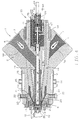
- Coextrusion head 1 includes an outer shell or housing 2 formed with a pair of inlet feed apertures 3 and 4 (FIG. 4), which are adapted to be threadably connected to delivery conduits (not shown) through which separate streams 6 and 7 of elastomeric stock flow from one or more extruders.
- the elastomeric material flows into individual separate material flow channels 6A and 7A which are formed within the extrusion head for subsequent delivery to the extrusion orifices as described below.
- Inlet aperture 3 communicates with inner flow channel 6A for inner flow stream 6 of an elastomeric material
- inlet aperture 4 communicates with flow channel 7A for outer flow stream 7 of an elastomeric material (FIG. 4).
- Outer stream 7 flows through channel 7A which is formed within shell 2 in a manner similar to that shown in the two patents set forth above, for subsequent discharge through an annular outer orifice 27 (FIG. 5) formed between a generally fixed outer die ring 11 and an inner annular anvil ring 9 which form outer die assembly 8.
- Ring 9 also is a component of an inner die assembly, indicated generally at 10 (FIGS. 4, 5 and 8), described in greater detail hereinafter.
- Temperature fluid control channels 12 and 13 are formed in shell 2 in order to permit heating and cooling of the interior thereof and, in particular, to maintain the die assemblies at the desired operating temperatures. These channels are connected to a source of heating and cooling fluid by conduits which extend into threaded apertures 14 and 15 of channel cover plates 16 (FIG. 4). Also, flat heat exchangers are mounted top and bottom on the large horizontal surface of shell 2 (not shown).
- An annular shaped member is mounted within outer shell 2 and forms in cooperation with outer shell 2 and with another cylindrical-shaped member 19, inner and outer flow channels 6A and 7A for fluid streams 6 and 7.
- a fixed extension tube 20 is threadably mounted on the forward end of innermost cylindrical member 19 and extends forwardly therefrom terminating adjacent the inner and outer die assemblies.
- Outer die assembly 8 (FIG. 5) includes a known annular outer die holder 21 adjustable mounted by a plurality of centering bolts 22 which extend through threaded openings 23 formed in the forward end of outer shell 2. Outer die ring 11 is secured in a fixed position by die holder 21 and by an outer die retaining nut 24 which is threadably engaged with outer die ring holder 21.
- Inner die assembly 10 (FIG. 5) includes a generally fixed annular-shaped anvil ring 9 which is a part of outer die assembly 8, spaced radially inwardly within outer die ring 11, which together with outer die ring 11 form annular outer extrusion orifice 27.
- Anvil ring 9 is telescopically mounted on the outer end of fixed extension tube 20 and is in abutment with a reinforcing-element-guide annular assembly 29 which is mounted against an annular shoulder 30 formed in the forward end of extension tube 20.
- Guide assembly 29 is similar to the guide assembly of previously noted U.S. Patent Nos.
- Reinforcing elements 31 generally take the form of filaments, threads, yarns or cords and include natural or synthetic textiles, steel, wire fiberglass, etc. and are encapsulated within the outer stream 7 of elastomeric material and merge therewith at the outer extrusion orifice 27 as disclosed in the two noted patents.
- coextrusion head 1 including shell 2, annular inner members 18 and 19, and the outer die assembly and reinforcing guide assembly, are well known in the art and form no particular part, per se, of the present invention, but are components within which the improvements of this invention are incorporated to form the improved coextrusion apparatus and for carrying out the improved method steps of the invention.
- inner die assembly 10 includes an inner die ring 35, shown particularly in FIGS. 4, 5 and 8 - 14. Ring 35 is connected to the extended end of an inner piston rod 36 which slideably extends within the hollow bore 37 of an outer piston rod 38.
- An annular pressure/volume compensating ring 40 is secured to the extended end of outer piston rod 38 and is slideably received and located within the inner cylindrical bore 41 formed by the cylindrical sidewall 42 of inner die ring 35 (FIG. 6).
- a plurality of air exhaust holes 43 are formed in the outer end wall 44, which is formed integrally with and forms the outer end of cylindrical wall 42 of inner die ring 35, to prevent the entrapment of air therein.
- inner die ring 35 terminates in a pair of stepped outer annular surfaces 45 and 45A, and a generally radially extending end surface indicated generally at 46, which includes a radial section 47 and a slightly tapered conical section 48.
- End surface 46 of inner die ring 35 forms inner extrusion orifice 49 in cooperation with the generally slightly conically extending annular end surface 50 of anvil ring 9.
- Inner orifice 49 communicates with an annular inner flow channel 52 which is formed between the outer surface of outer piston rod 38 and the inner surface of extension tube 20 and communicates with inner flow channel 6A.
- Piston rods 36 and 38 extend through the interior or bore of tube 20 as shown particularly in FIGS. 4 and 5.
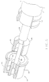
- piston actuation assembly 53 includes a hydraulic cylinder 54 which is threadably connected in an opening 51 formed in the rear wall of innermost annular member 19 (FIG. 4).
- Cylinder 54 is formed with a stepped inner bore indicated generally at 55, having a first chamber 56 in which is slideably mounted a piston 57 that is connected to outer piston rod 38.
- Piston 57 is a dual acting piston and has a center sealing O-ring 58 and a pair of fluid inlet and outlet ports 59 and 60 communicating with opposite sides of the piston.
- Fluid ports 59 and 60 extend through the body of hydraulic cylinder 54 and are connected to fluid lines 61.
- Another O-ring 62 is sealingly engaged with the sliding outer surface of outer piston rod 38 forwardly of piston 57.
- Outer piston rod 38 extends through a divider wall 64 and is in sliding sealing engagement therewith by another O-ring 65.
- the innermost end of outer piston rod 38 is connected to an encoder attachment 66.
- Encoder attachment 66 is connected with a shaft 67 to a linear encoder 68 which provides the feedback for the operational control of the improved coextrusion apparatus.
- Inner piston rods 36 is connected to a piston 70 which is slideably mounted within a second chamber 71 formed within the main hydraulic cylinder bore by a partition wall 72 and is slideably sealingly mounted therein by an O-ring 73.
- a pair of fluid inlet and outlet ports 74 and 75 communicate with chamber 71 on opposite sides of piston 70 to provide the dual action for the piston similar to that of piston 57 described above.
- Fluid lines 77 communicate with the fluid ports as shown in FIG. 7.
- Inner piston rod 36 is in sealing relationship with partition wall 72 by another O-ring 78 and with an end closure housing 79 of the hydraulic cylinder by an O-ring 76.
- Piston rod 36 is connected to another linear encoder 69 which provides the feedback for the operational control in a similar manner as encoder 68 of piston rod 38.
- inner and outer streams of rubber composition 6 and 7, respectively, are fed into coextrusion head 1 from extrusion apparatus well known in the art, and move through their respective flow channels 6A and 7A toward their respective extrusion orifices 27 and 49, respectively.
- Outer elastomeric stream 7 flows through outer extrusion orifice 27, as shown in FIG. 8, preferably containing reinforcing elements 31 embedded therein.
- Inner die ring 35 is shown in FIG. 8 in closed position completely closing inner orifice 49 by the abutting engagement of tapered wall section 48 of die ring 35 against the annular, preferably conical end surface 50 of anvil ring 9.
- a programmed control mechanism of a type well known in the art, is actuated and supplies hydraulic fluid into piston chamber 71 which will move inner piston 70 forwardly to enlarge orifice 49. Piston 70 will move inner piston rod 36 and attached die ring 35 axially in the forward, or left-hand direction as viewing FIG.
- compensating ring 40 will move axially inwardly in the direction of arrow A (FIGS. 9 and 10) generally simultaneously with the axial outward movement of inner die ring 35 in the direction of arrow B.
- the movement of compensating ring 40 is in a predetermined relationship with the outward movement of die ring 35 to reduce the volumetric area at the entrance to extrusion orifice 49 to maintain or achieve the required or desired pressure within the elastomeric material of inner stream 6 adjacent inner extrusion orifice 49.
- This action of the compensator 40 within the elastomeric stream provides for a smooth, even discharge flow rate of elastomeric material through inner orifice 49 and onto inner surface 81 of tubular extrudate 82.
- the terminating portion of the strip of material is placed in shear which provides for the smooth, ramped termination at the axial end of layer 84.
- the diameter of outer annular surface 45 of inner die ring 35 is less than the diameter of outer annular axially extending surface 89 of anvil ring 9 so that a space is provided indicated at 90 (FIG. 8), between inner surface 81 of extrudate 82 and surface 45 of inner die ring 35 to prevent the different elastomeric material of stream 7 from contacting surface 45 to prevent contamination thereof.
- radial end face 91 of outer die ring 11 terminates upstream from the outer radial face or end surface 50 of anvil ring 9 (FIGS. 8 - 13) a distance at least equal to the maximum width of inner extrusion orifice 49.
- This space relationship enables the flow of elastomeric material moving through orifice 49 to move in a generally radially outward direction for adhering to inner surface 81 of extrudate 82.
- inner elastomeric stream 6 will be of a different rubber composition than that of outer elastomeric stream 7.
- elastomeric stream 6 will be of a rubber composition having a higher imperviousness to air than that of the composition of outer elastomeric stream 7 to provide the air barrier for the pneumatic tire to prevent passage of the compressed air through the tire body.
- the rubber compositions of inner and outer elastomeric streams 6 and 7 can be varied to achieve various results desired in the making of pneumatic tires or other tubular products.
- inner cylindrical surface 93 of inner die ring cylindrical wall 42 will be in sliding engagement with the outer cylindrical surface 94 of compensating ring 40, as shown particularly in FIGS. 5 and 8, to provide a sliding relationship therebetween to prevent the passage therethrough of elastomeric material.
- the inner annular end face 95 of compensating ring 40 is concavely formed to assist in forming expansion chamber 85 upon its coordinated axial movement with inner die ring 35.
- Encoders 69 and 68 which are connected to piston rods 36 and 38, respectively, and the fluid supply lines associated therewith for controlling the pistons, are operatively connected by appropriate control circuitry to a programmable computer well known in the art. Such controlled movement enables the accurate control of the inner die ring and compensating ring for achieving the correct initiation and termination of inner elastomeric layer 84 in coordinated movement with the production of the outer tubular extrudate 82.
- computer control preferably is utilized to control the flow rate and pressure of streams 6 and 7 of elastomeric material as it leaves the external extruders and enters coextrusion head 1, and the tension of incoming reinforcing elements 31.
- the relationship between the flow rate or pressure of incoming streams 6 and 7 determines the thickness of the applied inner extrudate layer.
- the flow rate or pressure of elastomeric stream 6 will be correspondingly increased by the control computer as the die opens and decreased as the die closes to provide a uniform flow and pressure of elastomeric material through orifice 49.
- the thickness of inner extrudate layer 84 is determined in part by the flow rate or pressure imparted on incoming stream 6 by such computer control of the associated extruder.
- the improved apparatus and method of the invention provides for the accurately controlled application of an inner layer of an elastomeric material onto the inner surface of a continuously produced tubular extrudate to provide a smooth, preferably ramped initiation and cutoff of the inner layer with the extrudate, by compensating for the pressure changes at the inner extrusion orifice by an axially moveable compensating ring which moves in coordinated movement with a variable axially moveable inner die ring, which also enables the thickness of the inner layer to be regulated easily by adjusting the size of the inner extrusion orifice.
- the improved coextrusion apparatus and method is simplified, provides an effective, safe, inexpensive, and efficient device and operation which achieves all the enumerated objectives, provides for eliminating difficulties encountered with prior devices and methods, and solves problems and obtains new results in the art.
Landscapes
- Engineering & Computer Science (AREA)
- Mechanical Engineering (AREA)
- Manufacturing & Machinery (AREA)
- Extrusion Moulding Of Plastics Or The Like (AREA)
Claims (7)
- Koextrusionsmaschine zum Verändern des Innenprofils eines generell rohrförmigen Extrudats (82) während der Formung des Extrudats, bei der die Koextrusionsmaschine folgendes umfaßt:
einen äußeren Düsenzusammenbau (8) zur Ausbildung einer äußeren ringförmigen Extrusionsöffnung (27), zum Formen des rohrförmigen Extrudats, einen inneren Düsenzusammenbau (10), der einen axial beweglichen Düsenring (35) zur Ausbildung einer einstellbaren inneren Extrusionsöffnung (49) besitzt, erste Mittel (2,18,19) zur Ausbildung eines äußeren rohrförmigen Strömungsmittelkanals (7A) zur Abgabe eines ersten Stromes (7) elastomeren Materials zur äußeren Extrusionsöffnung (27) des äußeren Düsenzusammenbaus unter Formung des rohrförmigen Extrudats, und zweite Mittel (2,18,19,20) zur Ausbildung eines inneren rohrförmigen Strömungskanals zur Abgabe eines zweiten Stromes (6) elastomeren Materials zur inneren Extrusionsöffnung des inneren Düsenzusammenbaus, um wahlweise eine Schicht elastomeren Materials an einer Innenfläche (81) des rohrförmigen Extrudats abzulagern; und dritte Mittel zur Steuerung der Strömung des zweiten Stromes elastomeren Materials durch die innere Öffnung zur Veränderung der Menge elastomeren Materials, das an der Innenfläche des rohrförmigen Extrudats abgelagert wird, um das Profil der Innenfläche zu verändern, dadurch gekennzeichnet, daß das dritte Mittel einen axial beweglichen Kompensationsring (40) umfaßt, der mit der Axialbewegung des inneren Düsenrings (35) zusammenarbeitet, um den Druck innerhalb des zweiten Stromes (6) elastomeren Materials zu steuern, der sich durch die innere Extrusionsöffnung (49) bewegt und auf der Innenfläche (82) des rohrförmigen Extrudats abgelagert wird, und daß das dritte Mittel ferner eine erste strömungsmitteldruckbetätigte Vorrichtung (36) umfaßt, die am inneren Düsenring (35) angebracht ist, um denselben axial zur Einstellung der Größe der inneren Extrusionsöffnung (49) zu bewegen, die zwischen deren inneren Düsenring (35) und einem Ambossring (9) der inneren Extrusionsöffnung (49) gebildet ist, die zwischen dem inneren Düsenring (45) und dem Ambossring (9) ausgebildet ist, und daß eine zweite strömungsmitteldruckbetätigte Vorrichtung (38) mit dem Kompensationsring (40) verbunden ist, um denselben axial in einer Richtung zu bewegen, entgegengesetzt zur Bewegungsrichtung des inneren Düsenrings (35), wobei die erste (36) und zweite (38) strömungsmitteldruckbetätigte Vorrichtung eine erste bzw. zweite Kolbenstange darstellt, und daß der innere Düsenring (35) konzentrisch um den Kompensationsring (40) angeordnet ist und eine zylindrische Fläche (93) besitzt, die gleitend mit einer zylindrischen Außenfläche (94) des Kompensationsringes (40) in Eingriff steht, wobei der Kompensationsring (40) in einer ringförmigen Innenendfläche (95) endet, die eine Expansionskammer (85) in Verbindung mit dem inneren rohrförmigen Strömungskanal bildet, und wobei sich der Kompensationsring (40) in einer axialen Richtung entgegengesetzt zu der des inneren Düsenringes (35) bewegt, um den Druck innerhalb des zweiten Stromes (6) elastomeren Materials zu kompensieren, der durch Veränderung der Größe der Öffnung (49) nach Bewegung des inneren Düsenringes hervorgerufen wird. - Koextrusionsmaschine nach Anspruch 1, dadurch gekennzeichnet, daß der äußere Düsenzusammenbau (8) einen äußeren Düsenring (11) und einen inneren ringförmigen Ambossring (9) umfaßt, die die äußere Extrusionsöffnung (27) bilden, und wobei der Ambossring (9) ebenfalls die innere Extrusionsöffnung (49) mit dem axial beweglichen inneren Düsenring (35) bildet.
- Koextrusionsmaschine nach Anspruch 2, dadurch gekennzeichnet, daß jede Kolbenstange durch eine Strömungsmitteldruckquelle gesteuert wird, und wobei die erste Kolbenstange (36) innerhalb eines hohlen Inneren (37) der zweiten Kolbenstange (38) beweglich gelagert ist, und wobei ein sich axial erstreckendes hohles, rohrförmiges Glied (20) in einer koaxialen Beziehung um die erste (36) und zweite (38) Kolbenstange gelagert ist, und wobei der innere Strömungsmittelkanal (6A) zwischen dem Inneren des rohrförmigen Gliedes und dem äußeren der zweiten Kolbenstange (38) ausgebildet ist.
- Koextrusionsmaschine nach Anspruch 2, dadurch gekennzeichnet, daß der innere Düsenring (35) in einer axial unterstromigen Richtung vom Ambossring (9) angeordnet ist, und wobei der innere Düsenring und der Ambossring ringförmige Außenflächen (45,89) besitzen und wobei die ringförmige Außenfläche (45) des inneren Düsenrings einen kleineren Durchmesser als der der ringförmigen Außenfläche (89) des Ambossrings besitzt, um einen Kontakt der ringförmigen Außenfläche des inneren Düsenrings mit dem ersten Strom elastomeren Materials und dessen mögliche Verunreinigung zu verhindern.
- Koextrusionsmaschine nach Anspruch 2, dadurch gekennzeichnet, daß der innere Düsenring (35) und der Ambossring (9) axial beabstandete ringförmige Endflächen (48,50) besitzen, die die innere Extrusionsöffnung (49) bilden, und daß sich die ringförmigen Endflächen generell radial in Bezug zur Achse des rohrförmigen Extrudats erstrecken, so daß sich der Strom des elastomeren Materials in einer generell radialen Richtung durch die innere Öffnung bewegt, wenn er an der Innenfläche (81) des rohrförmigen Extrudats (82) abgelagert wird.
- Verfahren zum Verändern des Innenprofils eines generell rohrförmigen Extrudats während der Formung des Extrudats, wobei das Verfahren folgendes umfaßt:
Herstellen eines äußeren, unabhängig gesteuerten, kontinuierlichen, ringförmigen, hohlen Stromes (7) elastomeren Materials, das sich axial innerhalb eines Koextrusionskopfes (1) unter Bildung des generell rohrförmigen Extrudats (82) bewegt, und Herstellen eines inneren, unabhängig gesteuerten Stromes (6) elastomeren Materials innerhalb des Koextrusionskopfes, Auftragen des inneren Stromes elastomeren Materials in einer generell radialen Richtung auf eine Innenfläche (81) des rohrförmigen Extrudats in einer gesteuerten, variablen Weise, um das Innenprofil des Extrudats zu verändern, dadurch gekennzeichnet, daß das Verfahren ferner umfaßt:
Hindurchschicken des äußeren Stromes (7) elastomeren Materials durch eine ringförmige Öffnung (27) unter Bildung des rohrförmigen Extrudats (82) und Hindurchschicken des inneren Stromes (6) des elastomeren Materials durch eine veränderbare ringförmige Öffnung (49) unterstromig der ringförmigen Öffnung (27), wobei der innere Strom auf die Innenfläche (18) des Extrudats aufgetragen wird, Vorsehen einer Materialexpansionskammer (85), angrenzend an die veränderbare Extrusionsöffnung (49) und Verändern der Größe der Expansionskammer (85) in einer generell umgekehrten Beziehung zur Größe der veränderbaren Öffnung, um die Druckveränderung innerhalb des inneren Stromes elastomeren Materials zu kompensieren. - Verfahren nach Anspruch 6, dadurch gekennzeichnet, daß das Verfahren ferner folgendes umfaßt:
Anordnen der veränderbaren, ringförmigen Öffnung (49) des inneren Stromes (6) elastomeren Materials unterstromig von der festliegenden, ringförmigen Öfnung (27) in einer Entfernung die mindestens der maximalen Dicke des inneren Stromes des elastomeren Materials gleicht, das auf die Innenfläche (81) des Extrudats aufgetragen wird.
Applications Claiming Priority (2)
| Application Number | Priority Date | Filing Date | Title |
|---|---|---|---|
| US558061A US5128084A (en) | 1990-07-24 | 1990-07-24 | Coextrusion apparatus and method for varying the inner profile of a tubular extrudate |
| US558061 | 1990-07-24 |
Publications (3)
| Publication Number | Publication Date |
|---|---|
| EP0468261A2 EP0468261A2 (de) | 1992-01-29 |
| EP0468261A3 EP0468261A3 (en) | 1992-04-29 |
| EP0468261B1 true EP0468261B1 (de) | 1995-09-13 |
Family
ID=24228041
Family Applications (1)
| Application Number | Title | Priority Date | Filing Date |
|---|---|---|---|
| EP91111301A Expired - Lifetime EP0468261B1 (de) | 1990-07-24 | 1991-07-06 | Koextrusionsmaschine und Verfahren zum Verändern des Innenprofils eines rohrförmigen Extrudats |
Country Status (5)
| Country | Link |
|---|---|
| US (1) | US5128084A (de) |
| EP (1) | EP0468261B1 (de) |
| JP (1) | JP2530396B2 (de) |
| DE (1) | DE69112944T2 (de) |
| ES (1) | ES2076422T3 (de) |
Families Citing this family (18)
| Publication number | Priority date | Publication date | Assignee | Title |
|---|---|---|---|---|
| JPH08504595A (ja) * | 1992-12-18 | 1996-05-21 | ピルスベリー,カンパニー,ザ | 交換可能な面板を備えた押出しダイ |
| US5292472A (en) * | 1992-12-18 | 1994-03-08 | Bridgestone Corporation | Coextrusion apparatus and method with rotating cord guidance |
| IT1290520B1 (it) * | 1997-04-03 | 1998-12-04 | Pirelli | Metodo ed apparato di estrusione per realizzare fasce battistrada per pneumatici di veicoli |
| US5776519A (en) * | 1997-06-06 | 1998-07-07 | Graham Engineering Corporation | Parison extrusion head with quick change die ring clamp assembly |
| DE10007870C2 (de) * | 2000-02-21 | 2002-07-11 | Fischer W Mueller Blasformtech | Vorrichtung zum Herstellen von hohlkörperförmigen Artikeln aus thermoplastischem Kunststoff durch Saugblasen |
| FI111057B (fi) * | 2000-05-29 | 2003-05-30 | Conenor Oy | Ekstruusiomenetelmä ja ekstruusiolaite |
| RU2253568C2 (ru) * | 2003-01-09 | 2005-06-10 | Куликов Олег Леонидович | Устройство для формования термопластичного материала |
| RU2245249C1 (ru) * | 2003-04-08 | 2005-01-27 | Государственное образовательное учреждение высшего профессионального образования "Оренбургский государственный университет" | Матрица экструдера |
| US7738993B2 (en) * | 2003-10-10 | 2010-06-15 | Boston Scientific Scimed, Inc. | Extrusion of articles |
| BRPI0508323A (pt) | 2004-03-01 | 2007-07-24 | Aisapack Holding Sa | dose multicamada tendo uma superfìcie cÈncava |
| US20070190201A1 (en) * | 2006-02-13 | 2007-08-16 | Irwin Jere E | Extruder die assembly, extruder, and method |
| DE102007025507A1 (de) * | 2007-06-01 | 2008-12-04 | Vmi - Az Extrusion Gmbh | Ringextruder |
| MX2012008857A (es) * | 2010-02-01 | 2012-12-05 | Green Mountain Coffee Roasters Inc | Metodo y aparato para carbonatacion de bebidas a basadas en cartuchos. |
| WO2017180826A1 (en) * | 2016-04-15 | 2017-10-19 | Cc3D Llc | Head and system for continuously manufacturing composite hollow structure |
| US10232551B2 (en) | 2016-04-15 | 2019-03-19 | Cc3D Llc | Head and system for continuously manufacturing composite hollow structure |
| US10105910B2 (en) | 2016-04-15 | 2018-10-23 | Cc3D Llc | Method for continuously manufacturing composite hollow structure |
| KR20180134392A (ko) * | 2016-04-15 | 2018-12-18 | 씨씨3디 엘엘씨 | 복합 중공 구조체를 연속적으로 제조하기 위한 헤드 및 시스템 |
| CN113858589B (zh) * | 2021-10-27 | 2023-11-03 | 山东卓越管业有限公司 | 一种超大管径管材加工用的真空定型箱 |
Family Cites Families (33)
| Publication number | Priority date | Publication date | Assignee | Title |
|---|---|---|---|---|
| US2501690A (en) * | 1947-12-09 | 1950-03-28 | Carter Products Corp | Method and apparatus for making multiple layer plastic conduits |
| US2736921A (en) * | 1953-06-24 | 1956-03-06 | Us Rubber Co | Method and apparatus for forming self-sealing inner tube |
| US3078507A (en) * | 1958-11-19 | 1963-02-26 | Brockway Glass Co Inc | Method and apparatus for making plastic articles |
| DE1207606B (de) * | 1961-08-03 | 1965-12-23 | Rastatter Kunststoffwerk G M B | Vorrichtung zum Auspressen eines Schlauches unterschiedlicher Wandstaerke aus thermoplastischen Kunststoffen |
| US3944641A (en) * | 1961-10-02 | 1976-03-16 | Lemelson Jerome H | Process of forming an irregular surface on the inside of a tube or pipe |
| US3587281A (en) * | 1961-10-02 | 1971-06-28 | Jerome H Lemelson | Extrusion die apparatus |
| US3281896A (en) * | 1963-09-12 | 1966-11-01 | Dow Chemical Co | Parison extrusion die |
| US3453690A (en) * | 1967-05-26 | 1969-07-08 | Midland Ross Corp | Variable area extruder die-head |
| GB1370281A (en) * | 1971-09-02 | 1974-10-16 | Creators Ltd | Flexible plastics hoses |
| GB1456198A (en) * | 1972-11-29 | 1976-11-17 | Ici Ltd | Reinforced containers |
| DE2510127C2 (de) * | 1975-03-06 | 1983-09-22 | Battenfeld Maschinenfabriken Gmbh, 5882 Meinerzhagen | Strangpreßkopf zum Herstellen eines aus zwei konzentrischen, mit ihren Fließnähten versetzt zueinander angeordneten Schichten bestehenden Verbundschlauches aus thermoplastischem Kunststoff |
| US4029458A (en) * | 1975-06-24 | 1977-06-14 | The B.F. Goodrich Company | Extrusion die |
| US4047868A (en) * | 1975-08-12 | 1977-09-13 | Toppan Printing Co., Ltd. | Multilayer parison extrusion molding machine for blow molding |
| FR2332121A1 (fr) * | 1975-11-18 | 1977-06-17 | Raychem Aps | Extrudeuse a filiere multiple |
| US4149839A (en) * | 1975-12-30 | 1979-04-17 | Ishikawajima-Harima Jukogyo Kabushiki Kaisha | Blow molding apparatus |
| DE2654001C2 (de) * | 1976-11-27 | 1986-02-06 | Harald 5210 Troisdorf Feuerherm | Vorrichtung zum Herstellen von aus thermoplastischem Kunstoff bestehenden Hohlkörpern |
| US4171195A (en) * | 1977-11-17 | 1979-10-16 | Scientific Process & Research, Inc. | Cross-head die with volumetric flow compensation means |
| US4249875A (en) * | 1978-09-15 | 1981-02-10 | Cosden Technology, Inc. | Co-extrusion apparatus and method for producing multiple-layered thermoplastic pipe |
| CH640457A5 (de) * | 1979-05-28 | 1984-01-13 | Schiesser Ag | Verfahren und vorrichtung zur bildung der inneren wandteile von fahrzeugreifen. |
| DE3043204A1 (de) * | 1980-11-15 | 1982-07-01 | Mauser-Werke GmbH, 5040 Brühl | Austrittsduese |
| FR2503627A1 (fr) * | 1981-04-09 | 1982-10-15 | Raffinage Cie Francaise | Tete pour l'extrusion d'une paraison tubulaire a au moins une couche de matiere |
| US4465449A (en) * | 1982-12-06 | 1984-08-14 | Borg-Warner Chemicals, Inc. | Coextrusion feedblock for making lightweight, rigid thermoplastic pipe |
| DE3301248C2 (de) * | 1983-01-15 | 1987-01-02 | Mauser-Werke GmbH, 5040 Brühl | Strangpreßkopf |
| US4507071A (en) * | 1983-05-12 | 1985-03-26 | Cosden Technology, Inc. | Coextrusion apparatus for producing multiple layered thermoplastic pipe |
| DE3414444A1 (de) * | 1984-04-17 | 1985-10-17 | Continental Gummi-Werke Ag, 3000 Hannover | Strangpresse |
| US4578025A (en) * | 1984-11-21 | 1986-03-25 | Kazuo Ando | Die assembly for extruding multilayer parisons |
| US4657718A (en) * | 1985-02-22 | 1987-04-14 | The Firestone Tire & Rubber Company | Coextrusion method |
| US4578024A (en) * | 1985-02-22 | 1986-03-25 | The Firestone Tire & Rubber Company | Coextrusion apparatus |
| US4776909A (en) * | 1986-07-28 | 1988-10-11 | The Firestone Tire & Rubber Company | Method for making coextruded seamless tubular tire bodies for use in pneumatic tires |
| CA1303315C (en) * | 1988-09-16 | 1992-06-16 | Manfred A.A. Lupke | Apparatus for producing pipe with annular ribs |
| AU4283489A (en) * | 1988-11-23 | 1990-05-31 | American National Can Company | Apparatus for extrusion blow molding equipment, blow molding articles, parisons and containers made therefrom and methods for forming the same |
| US4946364A (en) * | 1989-05-31 | 1990-08-07 | Rcm, Ltd., Rubber Consulting & Machinery | Apparatus for manufacturing reinforced polymeric tubing |
| US5062782A (en) * | 1990-07-24 | 1991-11-05 | Bridgestone/Firestone, Inc. | Coextrusion apparatus for varying the inner and/or outer profile of a tubular extrudate |
-
1990
- 1990-07-24 US US558061A patent/US5128084A/en not_active Expired - Lifetime
-
1991
- 1991-07-06 ES ES91111301T patent/ES2076422T3/es not_active Expired - Lifetime
- 1991-07-06 DE DE69112944T patent/DE69112944T2/de not_active Expired - Fee Related
- 1991-07-06 EP EP91111301A patent/EP0468261B1/de not_active Expired - Lifetime
- 1991-07-23 JP JP3205715A patent/JP2530396B2/ja not_active Expired - Fee Related
Also Published As
| Publication number | Publication date |
|---|---|
| JPH06320597A (ja) | 1994-11-22 |
| EP0468261A2 (de) | 1992-01-29 |
| DE69112944T2 (de) | 1996-02-08 |
| DE69112944D1 (de) | 1995-10-19 |
| JP2530396B2 (ja) | 1996-09-04 |
| US5128084A (en) | 1992-07-07 |
| EP0468261A3 (en) | 1992-04-29 |
| ES2076422T3 (es) | 1995-11-01 |
Similar Documents
| Publication | Publication Date | Title |
|---|---|---|
| EP0468261B1 (de) | Koextrusionsmaschine und Verfahren zum Verändern des Innenprofils eines rohrförmigen Extrudats | |
| US5062782A (en) | Coextrusion apparatus for varying the inner and/or outer profile of a tubular extrudate | |
| EP0468260B1 (de) | Koextrusionsmaschine und Verwendung eines starren Düsenabschnitts zum Verändern des Aussenprofils eines rohrförmigen Extrudats | |
| EP0472864B1 (de) | Coextrusionsvorrichtung und -verfahren unter Verwendung einer elastischen Düse zum Verändern des Aussenprofils eines rohrförmigen Strangpresslings | |
| US4149839A (en) | Blow molding apparatus | |
| US4826423A (en) | Construction of thermoplastic tubes with tubular ribs by helical winding upon a mandrel | |
| EP0605767B1 (de) | Koextrusionsvorrichtung und Verfahren mit rotierender Kordelleitung | |
| EP0347200B1 (de) | Extrusionsdüsenaufbau und Extrusionsmethode | |
| US5055023A (en) | Apparatus for manufacturing large-volume hollow bodies of plastics material having multiple-layer walls | |
| JPH0655408B2 (ja) | 同時押出ヘッド及び同時押出方法 | |
| US9120262B2 (en) | Apparatus for extruding a polymeric material and extrusion head therefor | |
| US3841816A (en) | Apparatus for extruding tubing for fastener bags | |
| US4563147A (en) | Apparatus for extruding a tube | |
| US5206032A (en) | Apparatus for producing a preform for the manufacture of a hollow body from thermoplastic material | |
| US4723902A (en) | Balanced flow extrusion crosshead and die assembly | |
| US4145177A (en) | Air cooling ring for plastic film with independent lubricating air for film guide surface | |
| EP0213789B1 (de) | Ringkolbenspeicherkopf mit Verteilerhülse | |
| CA2017171C (en) | Apparatus for manufacturing reinforced polymeric tubing | |
| US4501629A (en) | Method and apparatus for extruding reinforced hose | |
| US3859017A (en) | Extrusion of sheath onto elongated support using decompression zones | |
| CN1072098C (zh) | 装有压出物颜色改变装置的挤压头 | |
| CN201253947Y (zh) | 一种用于挤出模具的熔体流量调节装置 | |
| EP1472071B1 (de) | Verfahren zur herstellung eines luftreifens und dabei verwendeter extruder | |
| GB1592176A (en) | Parison extrusion head | |
| US4495022A (en) | Extrusion method and apparatus |
Legal Events
| Date | Code | Title | Description |
|---|---|---|---|
| PUAI | Public reference made under article 153(3) epc to a published international application that has entered the european phase |
Free format text: ORIGINAL CODE: 0009012 |
|
| AK | Designated contracting states |
Kind code of ref document: A2 Designated state(s): DE ES FR GB IT |
|
| PUAL | Search report despatched |
Free format text: ORIGINAL CODE: 0009013 |
|
| AK | Designated contracting states |
Kind code of ref document: A3 Designated state(s): DE ES FR GB IT |
|
| 17P | Request for examination filed |
Effective date: 19920720 |
|
| 17Q | First examination report despatched |
Effective date: 19931013 |
|
| GRAA | (expected) grant |
Free format text: ORIGINAL CODE: 0009210 |
|
| AK | Designated contracting states |
Kind code of ref document: B1 Designated state(s): DE ES FR GB IT |
|
| REF | Corresponds to: |
Ref document number: 69112944 Country of ref document: DE Date of ref document: 19951019 |
|
| ET | Fr: translation filed | ||
| REG | Reference to a national code |
Ref country code: ES Ref legal event code: FG2A Ref document number: 2076422 Country of ref document: ES Kind code of ref document: T3 |
|
| ITF | It: translation for a ep patent filed | ||
| PLBE | No opposition filed within time limit |
Free format text: ORIGINAL CODE: 0009261 |
|
| STAA | Information on the status of an ep patent application or granted ep patent |
Free format text: STATUS: NO OPPOSITION FILED WITHIN TIME LIMIT |
|
| 26N | No opposition filed | ||
| REG | Reference to a national code |
Ref country code: GB Ref legal event code: IF02 |
|
| PGFP | Annual fee paid to national office [announced via postgrant information from national office to epo] |
Ref country code: FR Payment date: 20090708 Year of fee payment: 19 Ref country code: ES Payment date: 20090709 Year of fee payment: 19 |
|
| PGFP | Annual fee paid to national office [announced via postgrant information from national office to epo] |
Ref country code: GB Payment date: 20090612 Year of fee payment: 19 Ref country code: DE Payment date: 20090730 Year of fee payment: 19 |
|
| PGFP | Annual fee paid to national office [announced via postgrant information from national office to epo] |
Ref country code: IT Payment date: 20090731 Year of fee payment: 19 |
|
| GBPC | Gb: european patent ceased through non-payment of renewal fee |
Effective date: 20100706 |
|
| REG | Reference to a national code |
Ref country code: FR Ref legal event code: ST Effective date: 20110331 |
|
| PG25 | Lapsed in a contracting state [announced via postgrant information from national office to epo] |
Ref country code: DE Free format text: LAPSE BECAUSE OF NON-PAYMENT OF DUE FEES Effective date: 20110201 |
|
| REG | Reference to a national code |
Ref country code: DE Ref legal event code: R119 Ref document number: 69112944 Country of ref document: DE Effective date: 20110201 |
|
| PG25 | Lapsed in a contracting state [announced via postgrant information from national office to epo] |
Ref country code: IT Free format text: LAPSE BECAUSE OF NON-PAYMENT OF DUE FEES Effective date: 20100706 Ref country code: FR Free format text: LAPSE BECAUSE OF NON-PAYMENT OF DUE FEES Effective date: 20100802 |
|
| PG25 | Lapsed in a contracting state [announced via postgrant information from national office to epo] |
Ref country code: GB Free format text: LAPSE BECAUSE OF NON-PAYMENT OF DUE FEES Effective date: 20100706 |
|
| REG | Reference to a national code |
Ref country code: ES Ref legal event code: FD2A Effective date: 20110818 |
|
| PG25 | Lapsed in a contracting state [announced via postgrant information from national office to epo] |
Ref country code: ES Free format text: LAPSE BECAUSE OF NON-PAYMENT OF DUE FEES Effective date: 20100707 |