EP0468345A1 - Dispositif de chargement, de déchargement et de stabilisation pour pneus de véhicules - Google Patents
Dispositif de chargement, de déchargement et de stabilisation pour pneus de véhicules Download PDFInfo
- Publication number
- EP0468345A1 EP0468345A1 EP91111891A EP91111891A EP0468345A1 EP 0468345 A1 EP0468345 A1 EP 0468345A1 EP 91111891 A EP91111891 A EP 91111891A EP 91111891 A EP91111891 A EP 91111891A EP 0468345 A1 EP0468345 A1 EP 0468345A1
- Authority
- EP
- European Patent Office
- Prior art keywords
- tire
- unit
- fact
- unloading
- loading
- Prior art date
- Legal status (The legal status is an assumption and is not a legal conclusion. Google has not performed a legal analysis and makes no representation as to the accuracy of the status listed.)
- Granted
Links
Images


Classifications
-
- B—PERFORMING OPERATIONS; TRANSPORTING
- B29—WORKING OF PLASTICS; WORKING OF SUBSTANCES IN A PLASTIC STATE IN GENERAL
- B29D—PRODUCING PARTICULAR ARTICLES FROM PLASTICS OR FROM SUBSTANCES IN A PLASTIC STATE
- B29D30/00—Producing pneumatic or solid tyres or parts thereof
- B29D30/06—Pneumatic tyres or parts thereof (e.g. produced by casting, moulding, compression moulding, injection moulding, centrifugal casting)
- B29D30/0601—Vulcanising tyres; Vulcanising presses for tyres
- B29D30/0603—Loading or unloading the presses
-
- B—PERFORMING OPERATIONS; TRANSPORTING
- B29—WORKING OF PLASTICS; WORKING OF SUBSTANCES IN A PLASTIC STATE IN GENERAL
- B29D—PRODUCING PARTICULAR ARTICLES FROM PLASTICS OR FROM SUBSTANCES IN A PLASTIC STATE
- B29D30/00—Producing pneumatic or solid tyres or parts thereof
- B29D30/06—Pneumatic tyres or parts thereof (e.g. produced by casting, moulding, compression moulding, injection moulding, centrifugal casting)
- B29D30/0601—Vulcanising tyres; Vulcanising presses for tyres
- B29D30/0633—After-treatment specially adapted for vulcanising tyres
- B29D30/0643—Cooling during post cure inflation; Post cure inflators used therefor
-
- B—PERFORMING OPERATIONS; TRANSPORTING
- B29—WORKING OF PLASTICS; WORKING OF SUBSTANCES IN A PLASTIC STATE IN GENERAL
- B29C—SHAPING OR JOINING OF PLASTICS; SHAPING OF MATERIAL IN A PLASTIC STATE, NOT OTHERWISE PROVIDED FOR; AFTER-TREATMENT OF THE SHAPED PRODUCTS, e.g. REPAIRING
- B29C35/00—Heating, cooling or curing, e.g. crosslinking or vulcanising; Apparatus therefor
- B29C35/16—Cooling
- B29C2035/1658—Cooling using gas
Definitions
- the present invention relates to a vehicle tire loading-unloading and stabilizing device.
- the present invention relates to a device which may be employed to advantage for loading/unloading tires on/off a curing unit comprising an upper half mold, a lower half mold and a device for parting the two half molds at the end of each curing cycle; and wherein the two half molds are so formed that, when parted, the cured tire remains integral with the upper half mold.
- each tire upon extraction from the curing mold, to a stabilizing operation generally consisting in mounting the tire on a support, inflating it to a given pressure, usually of about 3 atmospheres, and maintaining this pressure long enough for the tire to cool from an initial temperature of about 180°C to below a given temperature, usually of about 100° C.
- post inflation provides, not only for preventing the synthetic cords from shrinking, thus resulting in undesired distortion of the tire, but also for stabilizing the shape of the cords, which is extremely useful in terms of finished tire quality.
- Stabilizing cured tires usually involves a number of drawbacks for the manufacturer, mainly due to the relatively long time required for cooling, and the size of currently used stabilizing equipment. Generally speaking, in fact, the time required at present for ensuring correct stabilization of the tire is roughly twice that required for curing. Consequently, two stabilizing machines are usually required for each curing mold, each of which machines usually features complex centralized systems for supplying cooling fluids such as water and/or air, for cooling the outer surface of the tires during stabilization.
- cooling fluids such as water and/or air
- the principal aim of the present invention is to provide a loading-unloading device designed to minimize the downtime involved on a tire manufacturing machine, particularly a curing unit of the aforementioned type, for loading and unloading the unprocessed and processed tires respectively; and which also provides for relatively fast cooling of the tires extracted from the curing mold, with no need for centralized systems.
- a device for loading- unloading and stabilizing vehicle in particular motor vehicle, tires, characterised by the fact that it comprises a mobile loading-unloading unit in turn comprising an upper unit for supporting a first tire, and a lower unit having means whereby to suspend a second tire; said upper unit being a stabilizing unit comprising means for supplying pressurized fluid inside said first tire and inflating the same to a given pressure; said supply means comprising a closed circuit for circulating said pressurized fluid, said circuit being defined at least partially by said first tire and comprising heat exchange means located outside said first tire, for cooling said pressurized fluid.
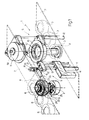
- Number 1 in Fig.1 indicates a tire curing system comprising a conveyor 2 for successively feeding green tires 3 to a loading station 4; a curing unit 5 for receiving tires 3 and producing cured tires 6; a conveyor 7 for transferring tires 6 from an unloading station 8; and a loading-unloading and stabilizing device 9 for transferring both tires 3 from loading station 4 to curing unit 5, and tires 6 from curing unit 5 to unloading station 8.
- Curing unit 5 is of known type as described, for example, in US Patent n.4,747,765, the content of which is fully incorporated herein.
- Unit 5 comprises a lower portion 10 and an upper portion 11 designed to move in relation to each other, by virtue of hydraulic lifting devices 12, between a closed curing position (not shown) and an open position (Fig.1) for unloading tire 6 and loading tire 3.
- Device 9 comprises two guide columns 13 extending upwards from a fixed base 14 and connected by an upper crosspiece 15 designed to move parallel to a vertical axis 16 in relation to base 14 by virtue of a hydraulic actuator 17.
- Crosspiece 15 is connected to a coupling 18 coaxial with axis 16 and connected to an actuator 19 so as to turn in relation to crosspiece 15 about axis 16.
- Device 9 also comprises a mobile loading- unloading and stabilizing unit 23 connected integral with the free end of portion 22 of arm 20.
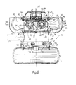
- unit 23 comprises an upper unit 24 for supporting and stabilizing tire 6, and a lower unit 25 for suspending tyre 3 coaxially with tire 6.
- unit 24 comprises a cylindrical body 26 integral with the free end of portion 22 of arm 20 and having a vertical axis 27.
- the top end of body 26 is fitted with the flat end wall 28 of a bell 29, the lateral wall 30 of which is bent upwards and defines unit 24 laterally.
- Wall 28 supports an annular body 31 via the interposition of a number of radial inserts 32 defining an annular passage 33 between wall 28 and the bottom end of annular body 31.
- Annular body 31 presents, on its top end, an outer groove defining a seat 34 for a bead portion 35 of tire 6, and is engaged by a lower portion of a toroidal body 36 extending upwards from annular body 31 and coaxial with axis 27.
- toroidal body 36 presents an annular groove 37 housing, in known manner by means of upper ring 38, an annular foot 39 for an annular bladder 40 which, when deflated, and as shown to the right in Fig.2, presents an outside diameter smaller than the inside diameter of tire 6.
- bladder 40 When inflated, on the other hand, by means of a pressurized fluid supply device (not shown), bladder 40 constitutes an annular element for supporting and retaining in fluidtight manner a bead portion 41 of tire 6.
- bladder 40 When inflated and contacting tire 6 mounted on toroidal body 36, bladder 40 defines, inside tire 6, a toroidal chamber 42 forming part of a circuit 43 for circulating a heat exchange fluid fed at a given pressure inside circuit 43 by a known valve device (not shown) for inflating tire 6.
- circuit 43 comprises a radiator 44 defined by two parallel pipes 45 extending transversely in relation to axis 27 through toroidal body 36, and defining, inside toroidal body 36, three passages 46 parallel to axis 27 and communicating at the bottom with passage 33 and at the top with the delivery side of a powered fan 47 coaxial with axis 27 and connected to the top end of toroidal body 36.
- pipes 45 For circulating said heat exchange fluid along circuit 43, pipes 45 house respective oppositely- oriented powered fans 48.
- pipes 45 also house respective inner conduits 49.
- a bell type conveyor 50 conveys the outside air to the inlet of fan 47 through an annular opening 51 defined between ring 38 and the periphery of conveyor 50.
- Unit 25 is connected integral with the bottom end of body 26, and comprises a known device 52 for gripping tire 3.
- Device 52 comprises, in known manner, a central actuator 53 integral with the bottom end of body 26 and having a number of output rods 54 moving substantially radially between a withdrawn position (not shown) and an expanded position (as shown in Fig.2).
- Each rod 54 is fitted on its free end with a pin 55 parallel to axis 27 and fitted on its bottom end with a substantially T-shaped bracket 56 designed to support and grip the bead portion of tire 3 and suspend tire 3 beneath body 26.
- actuator 19 is operated for positioning unit 23 over tire 3 in loading station 4; and actuator 17 is operated for lowering unit 23, gripping tire 3 via gripping device 52, and raising unit 23 with tire 3 suspended on unit 25.
- Actuator 19 is then operated once more for moving arm 20 towards curing unit 5 and positioning unit 23 between upper and lower portions 11 and 10 already opened by hydraulic devices 12.
- unit 23 is coaxial with portions 10 and 11 of curing unit 5, gripping device 52 is operated so as to withdraw rods 54 and drop tire 3 inside lower half mold 57 on lower portion 10 of unit 5. Unit 23 is then withdrawn from unit 5, which is closed for curing tire 3 and producing cured tire 6.
- unit 23 is moved into station 4 for picking up another tire 3 and transferring it to unit 5.
- portions 10 and 11 are parted by devices 12, which results, in known manner, in tire 6 being detached from lower portion 10 and remaining attached to upper portion 11.
- Unit 23 is then inserted once more between portions 10 and 11, so that unit 24 is located beneath tire 6 attached to portion 11, and unit 25, to which the next tyre 3 is suspended, is located over lower half mold 57.
- the next tire 3 is dropped on to half mold 57 by withdrawing rods 54 on device 52, and tire 6 is detached from portion 11 by a known extracting device 58 and dropped on to unit 24.
- bladder 40 Prior to detaching tire 6 from upper portion 11, bladder 40 is deflated and arranged as shown to the right in Fig.2. When detached from portion 11 of unit 5, tire 6 may thus drop on to toroidal body 36, with bead portion 35 substantially engaging seat 34, and bead portion 42 facing annular foot 39. At this point, pressurized fluid is fed into bladder 40 so as to inflate it as shown to the left in Fig.2, wherein bladder 40 axially locks and cooperates in substantially fluidtight manner with bead portion 41.
- unit 23 is then withdrawn from curing unit 5 and moved over to unloading station 8, during which displacement and a subsequent stop in station 8, pressurized heat exchange fluid, preferably of about 3 atmospheres, is fed into circuit 43 to inflate tire 6 and engage bead portion 35 in fluidtight manner with seat 34.
- Pressurized heat exchange fluid preferably of about 3 atmospheres
- Fan 47 and 48 are then activated, the first for supplying a stream of air through radiator 44 and, via passage 33, over the outer surface of tire 6, and the second for circulating said pressurized fluid inside circuit 43 and cooling tire 6 relatively rapidly from the inside.
- a vertical guide 60 is connected to an apron 59 fitted to lower portion 10 of unit 5 for connecting lifting devices 12.
- Guide 60 is defined, at its opposite ends, by two transverse plates 61 between which is mounted for rotation a screw 62 which, together with its drive motor 63, constitutes an actuator, similar to 17 in Fig.1, for moving along guide 60 a slide 64 similar to crosspiece 15 and connected in sliding manner to guide 60.
- Slide 64 is connected integral with a fork 65 supporting a rotary pin 66 extending along an axis 67 corresponding with axis 26 in Fig.
- Pin 66 is connected integral with the outer casing of an angular actuator 68 constituting a first portion of arm 20, the second portion 22 of which is connected to unit 23, extends along axis 21, and is designed to turn about axis 21 by virtue of actuator 68.
Landscapes
- Engineering & Computer Science (AREA)
- Mechanical Engineering (AREA)
- Moulds For Moulding Plastics Or The Like (AREA)
- Heating, Cooling, Or Curing Plastics Or The Like In General (AREA)
- Micro-Organisms Or Cultivation Processes Thereof (AREA)
- Tires In General (AREA)
Applications Claiming Priority (2)
| Application Number | Priority Date | Filing Date | Title |
|---|---|---|---|
| IT6759390 | 1990-07-27 | ||
| IT67593A IT1240508B (it) | 1990-07-27 | 1990-07-27 | Dispositivo di carico-scarico e stabilizzazione di pneumatici di veicoli |
Publications (2)
| Publication Number | Publication Date |
|---|---|
| EP0468345A1 true EP0468345A1 (fr) | 1992-01-29 |
| EP0468345B1 EP0468345B1 (fr) | 1995-09-13 |
Family
ID=11303710
Family Applications (1)
| Application Number | Title | Priority Date | Filing Date |
|---|---|---|---|
| EP91111891A Expired - Lifetime EP0468345B1 (fr) | 1990-07-27 | 1991-07-16 | Dispositif de chargement, de déchargement et de stabilisation pour pneus de véhicules |
Country Status (6)
| Country | Link |
|---|---|
| US (1) | US5198234A (fr) |
| EP (1) | EP0468345B1 (fr) |
| JP (1) | JP3287588B2 (fr) |
| DE (1) | DE69112948T2 (fr) |
| ES (1) | ES2077120T3 (fr) |
| IT (1) | IT1240508B (fr) |
Cited By (4)
| Publication number | Priority date | Publication date | Assignee | Title |
|---|---|---|---|---|
| EP2416948B1 (fr) * | 2009-04-08 | 2015-03-04 | Pirelli Tyre S.p.A. | Procede de fabrication des pneumatiques pour vehicule |
| CN105934318A (zh) * | 2014-01-22 | 2016-09-07 | 三菱重工机械科技株式会社 | 卸载装置 |
| WO2017108016A1 (fr) * | 2015-12-22 | 2017-06-29 | Harburg-Freudenberger Maschinenbau Gmbh | Dispositif de post-traitement de pneumatiques |
| EP3569395A1 (fr) * | 2018-05-17 | 2019-11-20 | Continental Reifen Deutschland GmbH | Procédé de vulcanisation d'un pneu, en particulier de pneu de véhicule, élément de mise en température ainsi que dispositif de vulcanisation |
Families Citing this family (7)
| Publication number | Priority date | Publication date | Assignee | Title |
|---|---|---|---|---|
| US5608630A (en) * | 1995-02-17 | 1997-03-04 | Poelouev; Avenir P. | Universal dynamic stabilizer |
| KR100301943B1 (ko) * | 1998-03-20 | 2001-09-22 | 구마모토 마사히로 | 타이어 가황기 |
| TWI295612B (en) * | 2004-11-11 | 2008-04-11 | Kobe Steel Ltd | Post cure inflator and vulcanized tire cooling method |
| WO2007079723A1 (fr) | 2006-01-10 | 2007-07-19 | Harburg-Freudenberger Maschinenbau Gmbh | Dispositif pour réaliser un post-traitement de pneumatiques |
| US7963755B1 (en) * | 2009-12-02 | 2011-06-21 | The Goodyear Tire & Rubber Company | Post cure rotational stations |
| DE102016000959A1 (de) * | 2016-01-26 | 2017-07-27 | Harburg-Freudenberger Maschinenbau Gmbh | Verfahren und Vorrichtung zur Nachbehandlung von Reifen |
| DE102016007315A1 (de) * | 2016-06-14 | 2017-12-14 | Harburg-Freudenberger Maschinenbau Gmbh | Verfahren und Vorrichtung zur Handhabung von Reifen |
Citations (5)
| Publication number | Priority date | Publication date | Assignee | Title |
|---|---|---|---|---|
| US3477100A (en) * | 1965-09-02 | 1969-11-11 | Chepos Z Chemickeho A Potrovin | Vulcanizing presses |
| US3495296A (en) * | 1967-05-25 | 1970-02-17 | Firwood Mfg Co | Post-inflating machine |
| US3621520A (en) * | 1967-06-12 | 1971-11-23 | Nrm Corp | Post cure inflator |
| US4092090A (en) * | 1977-05-18 | 1978-05-30 | Nrm Corporation | Tire curing system |
| US4702669A (en) * | 1985-10-24 | 1987-10-27 | Kabushiki Kaisha Kobe Seiko Sho | Mechanism for transferring cured tires from tire press to post-inflator |
Family Cites Families (16)
| Publication number | Priority date | Publication date | Assignee | Title |
|---|---|---|---|---|
| US2066265A (en) * | 1933-11-25 | 1936-12-29 | Wingfoot Corp | Method of curing tires |
| US3008180A (en) * | 1958-05-29 | 1961-11-14 | Goodyear Tire & Rubber | Apparatus for automatically post-cure inflating nylon tires |
| US3170187A (en) * | 1960-05-23 | 1965-02-23 | Nrm Corp | Tire curing press with dual post inflators |
| NL123663C (fr) * | 1960-08-19 | |||
| US3214791A (en) * | 1965-05-11 | 1965-11-02 | Firwood Mfg Company | Quadruple post-inflating machine |
| US3645660A (en) * | 1966-11-22 | 1972-02-29 | Uniroyal Inc | Apparatus for jet air cooling of tires during postinflation |
| US3483596A (en) * | 1967-06-12 | 1969-12-16 | Amk Subsidiary Corp | Tire post cure inflator |
| US3667881A (en) * | 1971-03-03 | 1972-06-06 | Goodrich Co B F | Tire cooling |
| US3692444A (en) * | 1971-05-05 | 1972-09-19 | Uniroyal Inc | Apparatus for cooling tires during post inflation |
| US3712769A (en) * | 1971-06-03 | 1973-01-23 | Goodrich Co B F | Fire loading apparatus with preheating device for green tires |
| US4452577A (en) * | 1982-07-09 | 1984-06-05 | Mitsubishi Jukogyo Kabushiki Kaisha | Tire loader |
| DE3381010D1 (de) * | 1982-07-23 | 1990-02-01 | Mitsubishi Heavy Ind Ltd | Verfahren und vorrichtung zum beladen von gruenen reifen. |
| US4527946A (en) * | 1982-09-29 | 1985-07-09 | Nrm Corporation | Tire curing press with pop-up, rotating nozzle |
| US4447385A (en) * | 1983-08-01 | 1984-05-08 | Nrm Corporation | Tire press, loader and method |
| IT1189674B (it) * | 1986-05-20 | 1988-02-04 | Firestone Int Dev Spa | Unita mobile di vulcanizzazione per pneumatici |
| IT1189673B (it) * | 1986-05-20 | 1988-02-04 | Firestone Int Dev Spa | Impianto di vulcanizzazione di pneumatici |
-
1990
- 1990-07-27 IT IT67593A patent/IT1240508B/it active IP Right Grant
-
1991
- 1991-07-03 US US07/725,847 patent/US5198234A/en not_active Expired - Lifetime
- 1991-07-16 DE DE69112948T patent/DE69112948T2/de not_active Expired - Fee Related
- 1991-07-16 EP EP91111891A patent/EP0468345B1/fr not_active Expired - Lifetime
- 1991-07-16 ES ES91111891T patent/ES2077120T3/es not_active Expired - Lifetime
- 1991-07-26 JP JP20870691A patent/JP3287588B2/ja not_active Expired - Fee Related
Patent Citations (5)
| Publication number | Priority date | Publication date | Assignee | Title |
|---|---|---|---|---|
| US3477100A (en) * | 1965-09-02 | 1969-11-11 | Chepos Z Chemickeho A Potrovin | Vulcanizing presses |
| US3495296A (en) * | 1967-05-25 | 1970-02-17 | Firwood Mfg Co | Post-inflating machine |
| US3621520A (en) * | 1967-06-12 | 1971-11-23 | Nrm Corp | Post cure inflator |
| US4092090A (en) * | 1977-05-18 | 1978-05-30 | Nrm Corporation | Tire curing system |
| US4702669A (en) * | 1985-10-24 | 1987-10-27 | Kabushiki Kaisha Kobe Seiko Sho | Mechanism for transferring cured tires from tire press to post-inflator |
Cited By (5)
| Publication number | Priority date | Publication date | Assignee | Title |
|---|---|---|---|---|
| EP2416948B1 (fr) * | 2009-04-08 | 2015-03-04 | Pirelli Tyre S.p.A. | Procede de fabrication des pneumatiques pour vehicule |
| US9744733B2 (en) | 2009-04-08 | 2017-08-29 | Pirelli Tyre S.P.A. | Process for manufacturing tyres for vehicle wheels |
| CN105934318A (zh) * | 2014-01-22 | 2016-09-07 | 三菱重工机械科技株式会社 | 卸载装置 |
| WO2017108016A1 (fr) * | 2015-12-22 | 2017-06-29 | Harburg-Freudenberger Maschinenbau Gmbh | Dispositif de post-traitement de pneumatiques |
| EP3569395A1 (fr) * | 2018-05-17 | 2019-11-20 | Continental Reifen Deutschland GmbH | Procédé de vulcanisation d'un pneu, en particulier de pneu de véhicule, élément de mise en température ainsi que dispositif de vulcanisation |
Also Published As
| Publication number | Publication date |
|---|---|
| ES2077120T3 (es) | 1995-11-16 |
| JP3287588B2 (ja) | 2002-06-04 |
| US5198234A (en) | 1993-03-30 |
| IT9067593A0 (it) | 1990-07-27 |
| JPH04226306A (ja) | 1992-08-17 |
| IT9067593A1 (it) | 1992-01-27 |
| EP0468345B1 (fr) | 1995-09-13 |
| DE69112948T2 (de) | 1996-04-11 |
| DE69112948D1 (de) | 1995-10-19 |
| IT1240508B (it) | 1993-12-17 |
Similar Documents
| Publication | Publication Date | Title |
|---|---|---|
| EP0468342B1 (fr) | Procédé de préchauffage, de cuisson et de stabilisation pour pneus de véhicules | |
| JP3236752B2 (ja) | タイヤの組立および加硫 | |
| EP0468345B1 (fr) | Dispositif de chargement, de déchargement et de stabilisation pour pneus de véhicules | |
| JP4493203B2 (ja) | 空気入りタイヤの製造方法 | |
| JP3668073B2 (ja) | タイヤ製造方法 | |
| US5820885A (en) | Tire vulcanizing system | |
| CZ132595A3 (en) | Tyre vulcanizer | |
| WO2002066238B1 (fr) | Dispositif de stockage de pneus crus avec vessies gonflables | |
| EP0139050B1 (fr) | Presse à pneus, chargeuse et procédé | |
| EP0468343B1 (fr) | Procédé et dispositif pour stabiliser du pneus vulcanisés | |
| JP6063949B2 (ja) | タイヤの加硫方法及びタイヤの製造方法 | |
| EP2072227B1 (fr) | Appareil de déchargement de pneu et procédé dans une ligne de vulcanisation | |
| CN100404224C (zh) | 加硫后充气处理装置的轮胎夹持装置 | |
| US20090160098A1 (en) | Tire building and cure station coupling apparatus and method | |
| EP0468344A1 (fr) | Dispositif de chargement et de déchargement pour pneus de véhicules | |
| BRPI0520302B1 (pt) | método e aparelho para vulcanização de pneus para rodas de veículo | |
| EP2329941B1 (fr) | Appareil pour refroidissement d'un pneu, presse de fabrication de pneu avec un tel appareil et procédé de fabrication d'un pneu | |
| JP7113131B2 (ja) | タイヤ加硫システム、加硫済みタイヤの製造方法及びタイヤ搬送装置 | |
| JP5078435B2 (ja) | 空気嚢の加硫方法および空気嚢加硫システム | |
| US11370188B2 (en) | Process and apparatus for unloading a vulcanised bicycle tyre from a vulcanisation press | |
| JP4571348B2 (ja) | タイヤ加硫システム | |
| JP6694267B2 (ja) | タイヤ製造装置 | |
| JPWO2020170353A1 (ja) | タイヤ加硫システム及び加硫済みタイヤの製造方法 | |
| JP4623882B2 (ja) | タイヤ加硫システム | |
| JPH05131452A (ja) | タイヤ加硫機のタイヤ取出装置 |
Legal Events
| Date | Code | Title | Description |
|---|---|---|---|
| PUAI | Public reference made under article 153(3) epc to a published international application that has entered the european phase |
Free format text: ORIGINAL CODE: 0009012 |
|
| AK | Designated contracting states |
Kind code of ref document: A1 Designated state(s): DE ES FR GB IT |
|
| 17P | Request for examination filed |
Effective date: 19920724 |
|
| 17Q | First examination report despatched |
Effective date: 19931215 |
|
| GRAA | (expected) grant |
Free format text: ORIGINAL CODE: 0009210 |
|
| AK | Designated contracting states |
Kind code of ref document: B1 Designated state(s): DE ES FR GB IT |
|
| REF | Corresponds to: |
Ref document number: 69112948 Country of ref document: DE Date of ref document: 19951019 |
|
| ITF | It: translation for a ep patent filed | ||
| ET | Fr: translation filed | ||
| REG | Reference to a national code |
Ref country code: ES Ref legal event code: FG2A Ref document number: 2077120 Country of ref document: ES Kind code of ref document: T3 |
|
| PLBE | No opposition filed within time limit |
Free format text: ORIGINAL CODE: 0009261 |
|
| STAA | Information on the status of an ep patent application or granted ep patent |
Free format text: STATUS: NO OPPOSITION FILED WITHIN TIME LIMIT |
|
| 26N | No opposition filed | ||
| RAP2 | Party data changed (patent owner data changed or rights of a patent transferred) |
Owner name: BRIDGESTONE CORPORATION |
|
| PGFP | Annual fee paid to national office [announced via postgrant information from national office to epo] |
Ref country code: GB Payment date: 19970620 Year of fee payment: 7 |
|
| PG25 | Lapsed in a contracting state [announced via postgrant information from national office to epo] |
Ref country code: GB Free format text: LAPSE BECAUSE OF NON-PAYMENT OF DUE FEES Effective date: 19980716 |
|
| GBPC | Gb: european patent ceased through non-payment of renewal fee |
Effective date: 19980716 |
|
| PGFP | Annual fee paid to national office [announced via postgrant information from national office to epo] |
Ref country code: FR Payment date: 20000707 Year of fee payment: 10 |
|
| PGFP | Annual fee paid to national office [announced via postgrant information from national office to epo] |
Ref country code: ES Payment date: 20000712 Year of fee payment: 10 |
|
| PGFP | Annual fee paid to national office [announced via postgrant information from national office to epo] |
Ref country code: DE Payment date: 20000727 Year of fee payment: 10 |
|
| PG25 | Lapsed in a contracting state [announced via postgrant information from national office to epo] |
Ref country code: ES Free format text: LAPSE BECAUSE OF NON-PAYMENT OF DUE FEES Effective date: 20010717 |
|
| PG25 | Lapsed in a contracting state [announced via postgrant information from national office to epo] |
Ref country code: FR Free format text: LAPSE BECAUSE OF NON-PAYMENT OF DUE FEES Effective date: 20020329 |
|
| PG25 | Lapsed in a contracting state [announced via postgrant information from national office to epo] |
Ref country code: DE Free format text: LAPSE BECAUSE OF NON-PAYMENT OF DUE FEES Effective date: 20020501 |
|
| REG | Reference to a national code |
Ref country code: FR Ref legal event code: ST |
|
| REG | Reference to a national code |
Ref country code: ES Ref legal event code: FD2A Effective date: 20020810 |
|
| PG25 | Lapsed in a contracting state [announced via postgrant information from national office to epo] |
Ref country code: IT Free format text: LAPSE BECAUSE OF NON-PAYMENT OF DUE FEES;WARNING: LAPSES OF ITALIAN PATENTS WITH EFFECTIVE DATE BEFORE 2007 MAY HAVE OCCURRED AT ANY TIME BEFORE 2007. THE CORRECT EFFECTIVE DATE MAY BE DIFFERENT FROM THE ONE RECORDED. Effective date: 20050716 |