EP2416948B1 - Procede de fabrication des pneumatiques pour vehicule - Google Patents
Procede de fabrication des pneumatiques pour vehicule Download PDFInfo
- Publication number
- EP2416948B1 EP2416948B1 EP10717753.7A EP10717753A EP2416948B1 EP 2416948 B1 EP2416948 B1 EP 2416948B1 EP 10717753 A EP10717753 A EP 10717753A EP 2416948 B1 EP2416948 B1 EP 2416948B1
- Authority
- EP
- European Patent Office
- Prior art keywords
- service drum
- annular anchoring
- anchoring structure
- loop
- service
- Prior art date
- Legal status (The legal status is an assumption and is not a legal conclusion. Google has not performed a legal analysis and makes no representation as to the accuracy of the status listed.)
- Not-in-force
Links
Images


Classifications
-
- B—PERFORMING OPERATIONS; TRANSPORTING
- B29—WORKING OF PLASTICS; WORKING OF SUBSTANCES IN A PLASTIC STATE IN GENERAL
- B29D—PRODUCING PARTICULAR ARTICLES FROM PLASTICS OR FROM SUBSTANCES IN A PLASTIC STATE
- B29D30/00—Producing pneumatic or solid tyres or parts thereof
- B29D30/06—Pneumatic tyres or parts thereof (e.g. produced by casting, moulding, compression moulding, injection moulding, centrifugal casting)
- B29D30/48—Bead-rings or bead-cores; Treatment thereof prior to building the tyre
-
- B—PERFORMING OPERATIONS; TRANSPORTING
- B29—WORKING OF PLASTICS; WORKING OF SUBSTANCES IN A PLASTIC STATE IN GENERAL
- B29D—PRODUCING PARTICULAR ARTICLES FROM PLASTICS OR FROM SUBSTANCES IN A PLASTIC STATE
- B29D30/00—Producing pneumatic or solid tyres or parts thereof
- B29D30/0016—Handling tyres or parts thereof, e.g. supplying, storing, conveying
-
- B—PERFORMING OPERATIONS; TRANSPORTING
- B29—WORKING OF PLASTICS; WORKING OF SUBSTANCES IN A PLASTIC STATE IN GENERAL
- B29D—PRODUCING PARTICULAR ARTICLES FROM PLASTICS OR FROM SUBSTANCES IN A PLASTIC STATE
- B29D30/00—Producing pneumatic or solid tyres or parts thereof
- B29D30/06—Pneumatic tyres or parts thereof (e.g. produced by casting, moulding, compression moulding, injection moulding, centrifugal casting)
- B29D30/48—Bead-rings or bead-cores; Treatment thereof prior to building the tyre
- B29D30/50—Covering, e.g. by winding, the separate bead-rings or bead-cores with textile material, e.g. with flipper strips
-
- B—PERFORMING OPERATIONS; TRANSPORTING
- B29—WORKING OF PLASTICS; WORKING OF SUBSTANCES IN A PLASTIC STATE IN GENERAL
- B29D—PRODUCING PARTICULAR ARTICLES FROM PLASTICS OR FROM SUBSTANCES IN A PLASTIC STATE
- B29D30/00—Producing pneumatic or solid tyres or parts thereof
- B29D30/06—Pneumatic tyres or parts thereof (e.g. produced by casting, moulding, compression moulding, injection moulding, centrifugal casting)
- B29D30/48—Bead-rings or bead-cores; Treatment thereof prior to building the tyre
- B29D2030/486—Additional components for the tyre bead areas, e.g. cushioning elements, chafers, flippers
-
- B—PERFORMING OPERATIONS; TRANSPORTING
- B29—WORKING OF PLASTICS; WORKING OF SUBSTANCES IN A PLASTIC STATE IN GENERAL
- B29D—PRODUCING PARTICULAR ARTICLES FROM PLASTICS OR FROM SUBSTANCES IN A PLASTIC STATE
- B29D30/00—Producing pneumatic or solid tyres or parts thereof
- B29D30/06—Pneumatic tyres or parts thereof (e.g. produced by casting, moulding, compression moulding, injection moulding, centrifugal casting)
- B29D30/48—Bead-rings or bead-cores; Treatment thereof prior to building the tyre
- B29D2030/487—Forming devices for manufacturing the beads
Definitions
- the present invention relates to a process for manufacturing tyres for vehicle wheels.
- the invention further relates to a process and an apparatus for reinforcing with a loop an annular anchoring structure of a tyre for vehicle wheels, said process and said apparatus being usable in carrying out the above process for manufacturing the tyre.
- a tyre for vehicle wheel generally comprises a carcass structure comprising at least one carcass ply comprised of reinforcing cords embedded in an elastomeric matrix.
- the carcass ply has end edges respectively engaged with annular anchoring structures arranged in the zones usually identified with the name of "beads" and normally consisting each of a substantially circumferential annular insert on which at least one filling insert is applied, in a radially outer position thereof.
- Such annular inserts are commonly identified as "bead cores” and have the task of keeping the tyre firmly fixed to the anchoring seat specifically provided in the rim of the wheel, thus preventing, in operation, the radially inner end edge of the tyre coming out from such a seat.
- the beads specific reinforcing structures (known, in the field of tyres, by the term: loops) may be provided, these reinforcing structures having the function of improving the torque transmission to the tyre.
- the bead region is particularly active in the torque transmission from the rim to the tyre during acceleration and braking, and therefore the provision of proper reinforcing structures in such zone ensures that the torque transmission takes place with the maximum possible reactivity.
- a belt structure comprising one or more belt layers is associated, said belt layers being arranged radially one on top of the other and having textile or metal reinforcing cords with crossed orientation and/or an orientation substantially parallel to the direction of circumferential extension of the tyre.
- under-belt a layer of elastomeric material, known as "under-belt" can be provided, said layer having the function of making the radially outer surface of the carcass structure as uniform as possible for the subsequent application of the belt structure.
- tread band In a radially outer position with respect to the belt structure a tread band is applied, also made of elastomeric material as well other structural elements making up the tyre.
- under-layer of elastomeric material
- said under-layer having properties suitable for ensuring a steady union of the tread band itself.
- the traditional processes for manufacturing tyres for vehicle wheels essentially provide for the components of the tyre listed above to be first made separately from one another, to be then assembled in a subsequent building step of the tyre.
- each component of the tyre is directly formed on a forming support, for example as illustrated in EP 0 928 680 in the name of the same Applicant.
- WO 2009/040594 in the name of the same Applicant, shows a process wherein the different building steps of the carcass structure are carried out at least in part simultaneously with the steps of making the crown structure at respective separate work stations, wherefrom the respective products must come out in a synchronised manner so as to proceed with the subsequent step of assembling the crown structure on the carcass structure and then, with the subsequent steps of the process for manufacturing the tyre.
- loop is used to indicate an annular element comprising one or more thread-like reinforcing elements substantially parallel to one another, such as textile or metal cords, optionally embedded in, or coated with, a layer of elastomeric material, such annular element being obtained by cutting to size a band-like element and reciprocally joining a head portion and a tail portion of such band-like element.
- elastomeric material on the other hand is used to indicate a composition comprising at least one elastomeric polymer and at least one reinforcing filler.
- a composition further comprises additives such as, for example, a cross-linking agent and/or a plasticizer. Thanks to the provision of the cross-linking agent, such material may be cross linked by heating, so as to make the end product.
- radial and axial and the expressions “radially inner/outer” and “axially inner/outer” are used by making reference to the radial direction and to the axial (or longitudinal) direction of a tyre (or of a drum used for building the tyre or one or more components of the type).
- circumferential and “circumferentially” instead, are used by making reference to the annular extension of the tyre/drum.
- US 4,450,025 discloses an apparatus and method for applying an envelope-type wrapping to tire bead rings.
- the apparatus includes a radially expansible drum, and an inflatable bladder that covers the drum and is interposed, along with the wrapping material, between the bead ring and the drum.
- the bladder is inflated and rolled over the bead ring.
- US 5,282,912 discloses a method and an apparatus for applying a belt-shaped bead filler on the bead core with apex.
- the method comprises the steps of: rotating a bead core with an apex together with a belt-shaped bead filler; mounting the bead filler on the internal circumferential surface so as to form an overlapping portion; folding up the bead filler on both sides of apex and bead core.
- US 4,927,488 discloses an apparatus for covering a tire bead with a tape.
- An annular tire bead is rotated by drive rollers held in contact with the inner circumferential surface of the bead, and during rotation of the bead a tape is fed and stuck onto the inner circumferential surface of the bead.
- the opposite side edge portions of this tape extending from this bead are stuck onto the opposite side surfaces of the bead by being pinched from opposite sides by flange portions of the drive rollers and flange members opposed thereto.
- the opposite side edge portions of the tape are then folded back onto the outer circumferential surface of the bead by means of scraper members, and thus the bead is perfectly covered by the tape.
- EP 1 724 100 discloses a tire production method and a bead member feeding device, enabling producing tires with different rim diameters one after the other.
- a tire production method and a bead member feeding device enabling producing tires with different rim diameters one after the other.
- plural sizes of bead members are stored in a container according to a production sequence including a sequence phase in which tires with different rim diameters are produced one after the other, and are removed from the container and fed to the green tires under production.
- US 5, 632, 836 shows, in figure 1 , a loop 6 wound about an annular anchoring structure 5, the latter comprising a plurality of bead cores 3 and a filling insert 4.
- EP 0 647 522 shows, in figure 7 , a loop 32 wound about an annular anchoring structure, the latter comprising a plurality of bead cores 30 and a filling insert 31.
- Loop 32 is first deposited on the annular outer surface of a service drum 6.
- the annular anchoring structure is then positioned on the loop 32, Loop 32 is then turned up about the annular anchoring structure by the effect of the thrust action exerted by lobes 11, 18 of the air tube 7 on the portions of loop 32 which axially extend from opposite sides with respect to the annular anchoring structure.
- Lobes 11, 18 are obtained by inflating an air tube 7 against a pair of annular bells 19, 20.
- the Applicant has further noted that when the loop comprises metal cords, an early deterioration of the air tube occurs because of the friction on the metal cords. It is therefore necessary to proceed with a certain frequency to replace the air tube, with consequent problems of cost and time.
- the Applicant has perceived that by having a forming support which is adjustable in radial direction it would be possible to loop in a sequence annular anchoring structures of different dimensions which are suitable for tyres with different fitting diameters, increasing consequently the production flexibility without reducing the plant productivity.
- the Applicant has therefore found that by providing a service drum that is radially expandable/contractable with respect to the longitudinal axis thereof it is possible, by using the same apparatus, to obtain the looping of annular anchoring structures (and thus, of tyres) having different radial dimensions. In fact, it is possible to adjust the service drum to a plurality of different operative radial positions, each operative radial position being selected according to the radial dimension of the annular anchoring structure to be used, and thus of the fitting diameter of the tyre to be manufactured.
- the present invention therefore relates to a process for manufacturing tyres for vehicle wheels, according to claim 1.
- the process described above allows achieving an advantageous usage flexibility, making it possible to use a single apparatus for carrying out the looping of annular anchoring structures having different radial dimension.
- an advantageous increase in the production yield is obtained when the radial dimension of the annular anchoring structure (and thus of the fitting diameter of the tyre to be manufactured) varies, as it is not necessary to replace the service drum and/or any further components/devices of the looping apparatus.
- the Applicant further notes that the possibility of using a single apparatus for looping annular structures with different radial dimensions allows achieving an advantageous containment of the initial investment costs and of the production costs. Such costs are further reduced as no air tubes are used, which as said above with reference to EP 0 647 522 are subject to early damage when loops comprising metal cords are used.
- the present invention relates to an apparatus for reinforcing with a loop an annular anchoring structure of a tyre for vehicle wheels, the apparatus having the features of claim 13.
- such an apparatus can be used for carrying out the processes discussed above and thus it allows achieving the advantageous results mentioned above.
- the present invention in at least one of the aforementioned aspects, can comprise at least one of the following preferred features, taken individually or in combination with the others.
- the process for manufacturing the tyre further comprises a step of positioning the reinforced annular anchoring structure on the end edge of the carcass ply, the above steps a) to g) being repeated by a predetermined number of times before carrying out the above positioning step.
- a plurality of reinforced annular anchoring structures such reinforced annular anchoring structures being obtained starting from a corresponding plurality of annular anchoring structures.
- the reinforced annular anchoring structures may be collected into proper storage members, wherefrom they are then picked up, during the manufacturing of a carcass structure of one or more tyres, for being positioned on the end edge of a carcass ply previously deposited onto a forming support. This implies an increase in the overall production yield of the apparatus for building the carcass structure.
- At least one of the aforementioned steps a) and b) is carried out at least in part simultaneously to at least part of at least one of the aforementioned steps c) to g).
- the step of turning the loop up is carried out at least in part simultaneously to at least part of at least one from step g) of unloading the reinforced annular anchoring structure from the service drum and step c) of loading a new annular anchoring structure onto the service drum.
- step c) of loading the annular anchoring structure onto the service drum comprises the steps of:
- step g) of unloading the reinforced annular anchoring structure from the service drum comprises the steps of:
- the radial contraction of the service drum allows an easy and immediate pick up of the annular anchoring structure just reinforced.
- step a) of setting the service drum to a predetermined operative radial dimension comprises a step of radially expanding the service drum until the annular outer surface thereof reaches a predetermined diameter selected according to the fitting diameter of the tyre to be manufactured.
- the possibility of varying the radial dimension of the service drum allows drastically reducing the setup time and cost for manufacturing tyres having different fitting diameters.
- step b) of depositing the loop onto an annular portion of an annular outer surface of the service drum and step c) of loading the annular anchoring structure onto the service drum in a radially outer position with respect to the loop a step of moving the service drum from a first work station defined at a feeding device of the loop to a second work station defined at a device for loading/unloading the annular anchoring structure onto/from the service drum is carried out.
- the provision of physically separate work stations for carrying out the steps of depositing the loop and loading/unloading the annular anchoring structure allows the simultaneous execution, on at least two different service drums, of at least part of the step of depositing the loop with at least part of at least one among the steps of loading the annular anchoring structure, turning the loop up and unloading the reinforced annular anchoring structure. Clear advantages in terms of productivity are thus obtained.
- the loop is obtained by cutting to size a band-like reinforcement element and step b) of depositing the loop onto an annular portion of an annular outer surface of the service drum comprises the steps of:-feeding the band-like reinforcement element towards the service drum;
- cutting the band-like reinforcement element is an integral part of the process for depositing the band-like reinforcement element on the service drum and takes place before the service drum has made a complete revolution.
- said predetermined angle ⁇ is equal to at least 360° and the band-like reinforcement element is cut to size before being fed towards the service drum.
- a step of associating an element made from elastomeric material on an outer side surface of the band-like reinforcement element is carried out.
- an element made from elastomeric material on the outer side surface of the band-like reinforcement element make easier a possible manual grip, by an operator, of the reinforced annular anchoring structure at the radially outermost portion thereof.
- Such element made from elastomeric material in fact, substantially covers any textile or metal cords projecting from the radially outer side surface of the band-like reinforcement element, preventing these cords from causing wounds or cuts to the operator.
- the aforementioned element made from elastomeric material carries out the same functions as that element made from elastomeric material, also known as intermediate elongated element, which is typically deposited between the loop, especially when it is made of metal, and the carcass ply in a step of the process for building the carcass structure following that of positioning the annular anchoring structure on the end edge of the carcass ply.
- the provision of the above element made from elastomeric material associated with the band-like reinforcement element in the process of the present invention therefore makes the depositing of the intermediate elongated element unnecessary.
- the aforementioned element made from elastomeric material is arranged astride the outer side surface of the band-like reinforcement element.
- the element made from elastomeric material is associated cantilevered to the outer side surface of the band-like reinforcement element.
- the annular portion of annular outer surface of the service drum is in an offset axial position with respect to a transversal middle plane of the service drum.
- step c) of loading the annular anchoring structure onto the service drum comprises the step of positioning the annular anchoring structure in a centred position with respect to a transversal middle plane of the service drum.
- the step of turning the loop up is carried out by moving in synchrony at least one pair of turning members with a combined motion along a first direction parallel to the longitudinal axis of the service drum and along a second direction perpendicular to the longitudinal axis of the service drum, said turning members being arranged on opposite sides with respect to a transversal middle plane of the service drum.
- the synchronous movement of the aforementioned turning members allows an even and effective deposition of the loop on the opposite surfaces of the annular anchoring structures.
- the service drum can rotate about the longitudinal axis thereof.
- the combination between rotating motion of the drum and combined motion of the turning members allows an even and effective deposition of the loop along the circumferential extension of the annular anchoring structure.
- two service drums are used, these service drums being arranged on opposite sides with respect to a pivoting axis and being integrally movable about said pivoting axis between a first work station defined at the device for feeding the loop and a second work station defined at the device for loading/unloading the annular anchoring structure.
- the provision of two service drums which can be integrally moved about a single pivoting axis between physically separate work stations allows the simultaneous execution of at least part of the step of depositing the loop with at least part of at least one among the steps of loading the annular anchoring structure, turning the loop up and unloading the reinforced annular anchoring structure.
- the service drum comprises a central shaft arranged coaxially to the above longitudinal axis and a plurality of support members arranged adjacent to one another in a circumferential direction about said central shaft and radially movable in synchrony between a position of maximum contraction and a position of maximum expansion.
- the synchronous movement in radial direction of the above support members carries out the radial expansion/contraction of the service drum and allows setting up the above drum to the radial position defined in the design stage based on the fitting diameter of the tyre to be manufactured.
- each support member comprises a central support body and two opposite side support bodies, the side support bodies being slidable in synchrony toward/away from the central body along a direction parallel to said longitudinal axis.
- each side support body of at least one of said support members comprises a radial opening extending longitudinally up to a free end facing the central support body.
- the aforementioned radial opening allows the turning members to position themselves in proximity of the annular anchoring structure while this is still supported by the side support bodies and by the central support body, to then proceed with the turning up of the loop.
- the present invention comprises a device for adjusting the radial movement of said support members and a device for locking said support members in position.
- the adjustment device comprises a guiding flange integrally associated with the central shaft, at least one helically-shaped sliding guide formed on said guiding flange, a plurality of radially extended sliding guides selectively coupled to the central shaft and a plurality of sliding blocks which extend radially with respect to said longitudinal axis.
- each of said sliding blocks is slidingly coupled to a respective radially extended sliding guide.
- each support member is integrally coupled to at least one respective sliding block and slidingly coupled to said at least one helically-shaped sliding guide.
- a predetermined angular movement of the central shaft causes a predetermined radial movement of each support member.
- the setup of the service drum to the desired radial position is achieved by simply rotating the aforementioned central shaft by a predetermined angle. Such rotation in fact causes a predetermined radial movement of the support members.
- the locking device comprises a calibration flange integrally associated with the central shaft and a pin elastically coupled to a respective radially extended sliding guide.
- said pin is movable between a first operating position wherein it is coupled in rotation to the central shaft - thus making the central shaft and the support members integral to one another in rotation and locking the support members in a radial position - and a second operating position wherein it is disconnected in rotation from the central shaft - thus achieving the radial movement of the support members.
- the locking device further comprises a pneumatic cylinder adapted to control the movement of said pin from said first operating position to said second operating position, or vice versa, in opposition to an elastic action exerted by a spring operatively arranged between the pin and one of said sliding guides.
- the device for turning the loop up comprises at least one pair of turning members arranged on opposite sides with respect to a transversal middle plane of the service drum.
- turning members are movable in synchrony with a combined motion along a first direction parallel to the longitudinal axis of the service drum and along a second direction perpendicular to the longitudinal axis of the service drum.
- each turning member is defined by a conical roller which can rotate about a rotation axis inclined with respect to the longitudinal axis of the service drum.
- the conical shape of the rollers allows the even deposition of the loop on the side surface of the annular anchoring structure during the movement of the rollers along the aforementioned two perpendicular axes.
- each turning member comprises a plurality of rollers arranged circumferentially one next to the other at a plurality of circumferences with respect to an axis perpendicular to the longitudinal axis of the service drum.
- roller-like configuration described above allows obtaining different peripheral speeds at the above circumferences, the angular speed being the same. In the practice, this leads to a more homogeneous deposition of the loop on the side surface of the annular anchoring structure.
- the device for loading/unloading the annular anchoring structure onto/from the service drum comprises at least one motorised arm for gripping and moving the annular anchoring structure.
- the device for loading/unloading the annular anchoring structure onto/from the service drum comprises two motorised arms for gripping and moving the annular anchoring structure.
- a first arm is intended to load the annular anchoring structure on the service drum and a second arm is intended to unload the reinforced annular anchoring structure from the service drum.
- the (or each) motorised arm comprises a member for gripping the annular anchoring structure with respect to a central axis.
- said gripping member also carries out a centring of the annular anchoring structure.
- the gripping and centring member comprises a plurality centring elements which are equally spaced in a circumferential direction and radially movable, in a synchronous manner, with respect to said central axis.
- a member for depositing an element made from elastomeric material on a side surface of the loop is provided.
- said depositing member comprises a plurality of rollers arranged one after the other along a moving direction of the loop, with at least some of the respective rotation axes which are skew to one another, in order to deposit said element made from elastomeric material astride the side surface of the loop.
- a first storage member for annular anchoring structures to be loaded onto the service drum and a second storage member for reinforced annular anchoring structures unloaded from the service drum are also provided.
- said first and second storage members belong to a moving line arranged in a position adjacent to the service drum.
- a third storage member for annular anchoring structures to be loaded onto the service drum is also provided, said third storage member being arranged upstream of the first storage member.
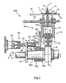
- FIG 1 with reference numeral 100 is globally indicated an exemplary embodiment of an apparatus for depositing a loop 5 ( figure 8 ) on an annular anchoring structure 10 ( figure 6 ) of a tyre for vehicle wheels, so as to manufacture reinforced annular anchoring structures 15 ( figure 8 ).
- Apparatus 100 allows carrying out a deposition process according to the present invention.
- the annular anchoring structure 10 comprises one substantially circumferential annular insert 11, also called bead core, and a filling insert 12 associated with the substantially circumferential annular insert 11 in a radially outer position thereof.
- the loop 5 is associated with the annular anchoring structure 10 so as to fully wrap the latter along the entire circumferential extension thereof and so that the two end edges 5a, 5b of loop 5 are offset in the radial direction ( figure 8 ) by at least a pair of millimetres (preferably about 5 mm).
- the reinforced annular anchoring structures 15 are intended to be used in the building of a carcass structure of the tyre. They are located in the tyre beads and are intended to keep the tyre well fixed to the anchoring seat specifically provided in the rim of the vehicle wheel.
- the building of the tyre carcass structure comprises at least the initial step of depositing a carcass ply on a forming support. Subsequently, each reinforced annular anchoring structure 15 is associated with each of the opposite end edges of the carcass ply.
- apparatus 100 comprises a member 101 for storing annular anchoring structures 10, a member 102 for storing reinforced annular anchoring structures 15 and a further member 103 for storing annular anchoring structures 10.
- the above storage members belong to a movement line (generally indicated in figure 1 by arrow L) and the storage member 103 is arranged along such a line upstream of the storage member 102, so as to take the place of the latter once all the annular anchoring structures arranged on the storage member 102 have been picked up. This in order to ensure a continuity of production of the reinforced annular anchoring structures 15.
- Each storage member 101-103 is substantially shaped as a cylindrical drum provided with longitudinal grooves 104 (for clarity of illustration, the reference numeral 104 is associated with only some of the above grooves) adapted to allow the gripping of the annular anchoring structures 10 from the storage member 101 at the radially inner surface of the substantially circumferential annular insert 11.
- the above grooves 104 also allow the unloading of the reinforced annular anchoring structures 15 on the storage member 102.
- the storage members 101-103 may however be of a different type than what described above; for example, they may be provided as baskets wherein the annular anchoring structures 10 or the reinforced annular anchoring structures 15 are stacked.
- the apparatus 100 comprises a service member 105 which can rotate about a pivoting axis Z-Z.
- the service member 105 comprises two opposite shafts 106a, 106b having respective longitudinal axes X-X which extend along a same direction perpendicular to axis Z-Z. Respective service drums 107a, 107b, totally identical to one another, are mounted on shafts 106a, 106b, each service drum being capable of rotating about the respective longitudinal axis X-X.
- the position of the service drums 107a, 107b may be exchanged to allow carrying out in a sequence, on each of them, the deposition of the loop 5, the positioning of the annular anchoring structure 10 in a radially outer position with respect to the loop 5 and the turning up of the loop 5 about the annular anchoring structure 10, so as to form the reinforced annular anchoring structure 15.
- the loop 5 is deposited on the service drum 107a whereas the annular anchoring structure 10 is positioned on the service drum 107b in a radially outer position with respect to the loop 5 and the loop 5 is turned up about the annular anchoring structure 10.
- the service drums 107a, 107b are moved integrally in rotation about the pivoting axis Z-Z exchanging their position; the service drum 107a therefore moves in the operating position occupied in figure 1 by drum 107b and vice versa.
- the annular anchoring structure 10 is positioned on the service drum 107a in a radially outer position with respect to a previously deposited loop 5, such loop 5 is turned about the annular anchoring structure 10 for forming the reinforced annular anchoring structure 15, and the reinforced annular anchoring structure 15 is unloaded.
- a new loop 5 is deposited on the service drum 107b for making a new reinforced annular anchoring structure 15, the previously formed reinforced annular anchoring structure 15 having been removed from the service drum 107b.
- the use of two service drums 107a, 107b allows carrying out at least part of the steps carried out at the service drum 107a simultaneously with at least part of the steps carried out on the service drum 107b.
- Apparatus 100 of the present invention shall be described hereinafter with reference to the operating position of the service drums 107a, 107b illustrated in figure 1 .
- a device 130 for loading the annular anchoring structure 10 on the service drum 107b and unloading the reinforced annular anchoring structure 15 from the service drum 107b is operatively interposed between the storage members 101, 102 and 103 and the service member 105.
- device 130 comprises a first motorised arm 131 which can be moved with articulated motion between the storage member 101 and the service member 105 for taking the annular anchoring structure 10 from the storage member 101 and loading it on the service drum 107b.
- Device 130 also comprises a second motorised arm 135 which can be moved with articulated motion between the service member 105 and the storage member 102 of the reinforced annular anchoring structures 15 for unloading the reinforced annular anchoring structure 15 from the service drum 107b and placing it on the storage member 102.
- the motorised arm 131 is rotatable about a rotation axis Z'-Z' parallel to the rotation axis of the service member 105 and comprises, at a free end thereof, a gripping member 132 of the annular anchoring structure 10.
- the motorised arm 135 is rotatable about the above rotation axis Z'-Z' and comprises, at a free end thereof, a gripping member 136 of the reinforced annular anchoring structure 15.
- Figure 1 shows a step of the process of the present invention wherein the motorised arms 131, 135 rotate in counter clockwise with respect to the rotation axis Z'-Z'.
- the motorised arm 131 has just loaded an annular anchoring structure 10 on the service drum 107b and is moving from the service drum 107b towards the storage member 101 for taking a new annular anchoring structure 10;
- the motorised arm 135, on the other hand has just unloaded on the storage member 102 an annular anchoring structure 15 previously taken from the service drum 107b and is moving from the storage member 102 towards the service drum 107b for taking a new reinforced annular anchoring structure 15.
- the gripping members 132 and 136 are identical. For simplicity of description and clarity of illustration, only one of them is described hereinafter (in particular the gripping member 132), it being understood that the elements described below with reference to such a gripping member are also provided in the gripping member 136. Therefore, what said below with reference to the gripping member 132 also applies to the gripping member 136.
- the gripping member 132 is rotatable with respect to a longitudinal extension axis Y-Y of the motorised arm 131 and is linearly movable in both directions along a direction perpendicular to said axis Y-Y (such direction is indicated in figure 1 with arrow P).
- the gripping member 132 comprises a plurality of gripping and centring arms 133 (for clarity of illustration, numeral reference 133 is associated to only one of the above arms) equally spaced in a circumferential direction with respect to a central axis of the gripping member 132 and radially movable, in a synchronous manner, with respect to the above central axis. Such radial movement allows gripping, centring and unloading the annular anchoring structure 10.
- apparatus 100 comprises a device for depositing the loop 5 on the service drum 107a.
- the loop 5 is obtained by cutting to size a band-like reinforcement element 50 previously collected on a reel 51.
- the band-like reinforcement element 50 which is associated with a service fabric, is unwound from such reel 51. Thanks to the interaction provided by a first contrast roller 54 the service fabric leaves the band-like reinforcement element 50 and is collected on a first winding roller 55. After that, the band-like reinforcement element 50, deviated by a first diverter roller 52 and by a second diverter roller 53, is properly fed on a portion of the annular outer surface 108 of the service drum 107a by a suitable feeding device 140.
- Reel 51, diverter rollers 52 and 53, the first contrast roller 54 and the first winding roller 55 are preferably housed inside a support frame 20 arranged in a position adjacent the service member 105.
- the feeding device 140 comprises, downstream of the second diverter roller 53, an output portion 145 supported cantilevered from the frame 20 and suitably oriented towards the annular outer surface 108 of the service drum 107a.
- the output portion 145 of the feeding device 140 is tilted by a predetermined angle with respect to a horizontal plane and points from top downwards on the annular outer surface 108 of the service drum 107a.
- the feeding of the band-like reinforcement element 50 towards the service drum 107a is obtained by a device 160 for capturing and moving the band-like reinforcement element 50.
- such device 160 comprises at least one pair of suction cups 161 whose movement causes the unwinding of the band-like reinforcement element 50 from the reel 51 and thus, the feeding of the band-like reinforcement element 50 on the annular outer surface 108 of the service drum 107a.
- suction cups 161 carry the head of loop 5 from the cutting zone to the service drum 107a.
- a depositing roller (not shown in the figures), preferably made from elastomeric material, is rested onto the head of loop 5, and after the suction cups 161 have released the grip on the loop 5, the service drum 107a starts rotating.
- the pressure the depositing roller creates on loop 5 during the deposition ensures the friction/adhesion between loop 5 and service drum 107a, necessary for winding the loop 5 on the service drum itself, thus carrying out the deposition step.
- suction cups 161 it is possible to use suction members or, if the band-like reinforcement element 50 comprises metal cords, an electromagnet device, all of the conventional type.
- Apparatus 100 of the present invention further comprises a cutting member 170 of the band-like reinforcement element 50.
- the cutting member 170 is arranged at the output portion 145 of the feeding device 140 of the band-like reinforcement element 50 and comprises a disc blade 172 of the conventional type.
- apparatus 100 of the present invention comprises a member 190 for depositing an element of an elastomeric material 60 on an outer surface (with respect to the upward direction of axis Z-Z, that is in the direction away from the support plane of the feeding device 140) of the band-like reinforcement element 50.
- member 190 is arranged between the diverter rollers 52 and 53 of the feeding device 140.
- the element of elastomeric material 60 which is also associated with a service fabric, is collected in a reel 61 housed in the support frame 20. Thanks to the interaction provided by a second contrast roller 64, the service fabric leaves the element of elastomeric material 60 and is collected on a second winding roller 65. After that, the element of elastomeric material 60 unwound from the above reel 61 is deviated by the diverter roller 52 and, by means of the member 190, it is suitably positioned on the outer side surface of the band-like reinforcement element 50 ( figure 1 ).
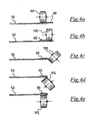
- the element of elastomeric material 60 is arranged astride the outer side surface of the band-like reinforcement element 50, so as to take the configuration shown in figure 4e (before cutting the reinforcement element 50 for obtaining the loop 5) and in figure 8 (after turning the loop 5 up about the annular anchoring structure 10).
- the element of elastomeric material 60 may be arranged cantilevered on the outer side surface of the band-like reinforcement element 50.
- the element of elastomeric material 60 is coupled to the end edge 5b of loop 5 which is intended, when loop 5 is turned up about the annular anchoring structure 10, to be in a radially outer position with respect to the other end edge 5a.
- member 190 comprises a plurality of rollers (five in the embodiment shown, indicated with reference numerals 191-195) arranged in one after the other along the movement direction M of the band-like reinforcement element 50; at least some of such rollers have a rotation axis which is skewed with respect to the rotation axis of at least some of the other rollers.
- the rotation axis of the second roller 192 is parallel to that of the first roller 191, but it is arranged at a lower height with respect to the axis of roller 191 with reference to the movement plane of the band-like reinforcement element 50.
- the rotation axis of the third roller 193 is skewed with respect to that of rollers 191 and 192.
- the rotation axis of the fourth roller 194 is skewed with respect to that of rollers 191-193; in particular, it is inclined opposite to the axis of roller 192 with respect to the movement plane of the band-like reinforcement element 50.
- the rotation axis of the fifth roller 195 is parallel to that of rollers 191 and 192, but it is arranged opposite to the roller 191 with respect to the movement plane of the band-like reinforcement element 50.
- rollers 191-195 allows depositing the element of elastomeric material 60 astride the outer side surface of the band-like reinforcement element 50 while the latter is fed towards the service drum 107a.
- each of the service drums 107a, 107b is radially expandable/contractable so as to be set to a plurality of predetermined radial dimensions selected according to the tyre to be manufactured.
- drum 107a comprises a plurality of support members 110 arranged adjacent each other along a circumferential direction and coaxial to the axis X-X.
- said support members 110 are radially movable in a synchronous manner with respect to axis X-X in the two opposite ways of the direction indicated in figure 2 by arrow R, between a maximum contraction position and a maximum expansion position.
- the support members 110 are at least eight. More preferably, such members are in a number comprised between twelve and twenty-four.
- Each support member 110 comprises a central support body 111 and two opposite side support bodies 112 arranged at opposite sides with respect to the central body 111 along the circumferential direction. Such members define the annular outer surface 108 of the service drum 107a.
- the central support body 111 comprises a fork-like radially inner portion 111a and a radially outer portion 111b which supports the loop 5 ( figure 2 also shows the annular anchoring structure 10 in a radially outer position with respect to the loop 5; such configuration occurs when drum 107a moves to the position occupied in figure 1 by drum 107b).
- the two side support bodies 112 are slidingly mounted on a guide 113 which extends parallel to axis X-X and which is integral to the radially outer portion 111b of the central support body 111.
- the side support bodies 112 can therefore be moved parallel to the rotation axis X-X of the service drum 107a towards one other and away from one another with respect to the central support body 111.
- each of the side support bodies 112 comprises a radial opening 112a extended axially up to a free end facing the central support body 111.
- the function of such opening will appear clearly in the following part of the present description.
- the radial movement of the support members 110 is achieved by means of a specifically provided adjustment device 114 described hereinafter.
- Such adjustment device 114 comprises an annular flange 115 fitted on the shaft 106a.
- Such flange 115 is integral in rotation with the shaft 106a.
- Respective helically-shaped sliding guides 116 are formed on the opposite side faces of flange 115. In particular, such guides 116 are shaped according to an Archimedes spiral.
- the central support body 111 at each arm of the fork portion 111a, carries a pin 117 housed in a respective sliding guide 116.
- the fork portion 111a moreover, is integrally associated with a pair of sliding blocks 118 (only one of which is shown in figure 2 ) extended in the radial direction; each of said sliding blocks is slidingly mounted on a respective radially extended sliding guide 119 (only one of which is shown in figure 2 ).
- One of the sliding guides 119 may be selectively made integral in rotation with shaft 106a; in such configuration, a predetermined angular movement of shaft 106a causes a predetermined radial movement of each support member 111.
- apparatus 100 of the present invention comprises a locking device 120 active on one of the support members 110, as shown always in figure 2 .
- the locking device 120 comprises a calibration flange 121 fitted on the shaft 106a so as to be integral in rotation with the latter.
- flange 121 has, at the radially outer surface thereof, a plurality of slits 122 arranged along the whole circumferential extension of flange 121.
- the locking device 120 further comprises a cylindrical pin 123 slidingly associated, through a spring 124, to a sleeve 123a integral to the radially extended sliding guide 119 and pivotally mounted on the shaft 106a by the interposition of a pair of rolling bearings 119a.
- spring 124 is a compression spring interposed between a free end surface of sleeve 123a and an abutment flange 125 integral to pin 123.
- Pin 123 is housed in one of slits 122 and comprises, opposite to the spring 124 with respect to the abutment flange 125, a slit 126 extending by only part of the circumferential extension of the pin itself.
- the locking device 120 further comprises, opposite to the sleeve 123a with respect to the pin 123, a pneumatic cylinder 127 adapted to control the movement of pin 123, in opposition to the elastic action exerted by spring 124, between a first operating position, shown in figures 2 and 3a , wherein pin 123 is in such an axial position that slit 126 is axially shifted with respect to slit 122 of the calibration flange 121, and a second operating position, shown in figure 3b , wherein pin 123 is in such an axial position that slit 126 is radially aligned with slit 122 of the calibration flange 121.
- pin 123 is coupled in rotation with the calibration flange 121, thus making the radially extended sliding guide 119 (and thus the support member 110) and shaft 106a integral in rotation.
- the radial position of the support members 110 is not altered by the rotation of shaft 106a; thus, the service drum 107a rotates without radially expanding/contracting.
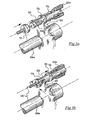
- Apparatus 100 further comprises, at the position occupied by the service drum 107b, a device 180 for turning loop 5 up about the annular anchoring structure 10.
- the turning up device 180 comprises a pair of turning rollers 181 arranged on opposite sides with respect to a transversal middle plane C of the service drum 107b.
- Such rollers 181 are movable in synchrony with a combined motion along both ways of a first direction A parallel to the longitudinal axis X-X of the service drum 107b and along both ways of a second direction B perpendicular to the longitudinal axis X-X of the service drum 107b.
- Rollers 181 therefore are axially and radially movable in a synchronous manner with respect to the service drum 107b along a path that reproduces the profile of the annular anchoring structure 10.
- the above synchronised radial movement of rollers 181 allows loop 5 to be turned up about the annular anchoring structure 10 for forming the reinforced annular anchoring structure 15.
- Each roller 181 preferably has a conical shape and is idly rotatable about a rotation axis R which is tilted with respect to the longitudinal axis X-X of the drum.
- the rotation of rollers 181 about the respective axes R takes place by the effect of the dragging action exerted by loop 5 when the service drum 107b is made to rotate about its longitudinal axis X-X.
- FIGS 5-7 show three subsequent steps of the turning up operation.
- the side support members 112 are brought close to the side of the central support member 111 so that the loop is radially supported by both the side support members 112 and the central support member 111.
- Rollers 181 have been inserted from the top through the radial openings 112a of the side support members 112 to be in the position shown in figure 5 .
- Figure 6 shows a subsequent step wherein the side support members 112 are moved away from the central support member 111 for allowing rotation of the service drum 107b (and thus of the side support members 112) about the longitudinal axis X-X and, concurrently with such rotation, movement of rollers 181 along directions A and B (as shown by a dashed line in figure 5 ), so as to carry out the turning up of loop 5 about the annular anchoring structure 10.
- Figure 7 shows an even subsequent step, wherein the service drum 107b has been made to rotate about the longitudinal axis X-X and rollers 181 have completed the turning up of loop 5, thus obtaining the reinforced annular anchoring structure 15 (shown in a section in figure 8 ).
- FIG 9 shows an alternative embodiment of the turning rollers, now indicated with reference numeral 182.
- Rollers 182 are each defined by a plurality of small rollers (all indicated with reference numeral 183) arranged circumferentially one next to the other at a plurality of circumferences with respect to an axis T perpendicular to the longitudinal axis X-X of the service drum 107b. Rollers 183 are therefore arranged on a base element 184 along a plurality of rays around axis T. They are mounted on the base element 184 through the interposition of respective bearings 185.
- rollers 182 for carrying out the turning up of loop 5 about the annular anchoring structure 10 is identical to that described above with reference to rollers 181. They are therefore moved in a synchronous manner with combined motion along directions A and B following the profile of the annular anchoring structure 10.
- the rotation of rollers 183 takes place by the effect of the dragging action exerted by loop 5 when the service drum 107b is made to rotate about its longitudinal axis X-X.
- the support members 110 of the service drum 107a are radially moved for setting the service drum 107a to a radial position selected on the basis of the fitting diameter of the tyre to be manufactured.
- pin 123 of the locking device 120 is in the position shown in figure 3b . Being pin 123 in this position, the rotation of shaft 106a of the service drum 107a about axis X-X causes the radial movement of the support members 110. Such support members 110, however, are disconnected from shaft 106a. Therefore, rotation of shaft 106a does not cause rotation of the service drum 107a.
- the side support members 112 of support members 110 are close to the respective central support members 111, so as to define a substantially continuous annular outer surface 108 of the service drum 107a in the circumferential direction.
- the locking device 120 is actuated moving pin 123 to the position of figures 2 and 3a .
- the support members 110 are coupled to shaft 106a and thus rotation of shaft 106a about axis X-X causes a corresponding rotation of the service drum 107a. No radial movement of the support members 110 takes place in this case.
- a head portion of the band-like reinforcement element 50 is captured by suction cups 161 and moved onto the annular outer surface 108 of the service drum 107a.
- the unwinding of the band-like reinforcement element 50 from reel 51 is caused by the movement of the band-like reinforcement element 50 towards the service drum 107a.
- the service drum 107a is now moved in rotation about axis X-X. Because of the sticking of the head portion of the band-like reinforcement element 50 with the annular outer surface 108 of the service drum 107a, the band-like reinforcement element 50 is forced to follow the rotation of the service drum 107a; subsequent portions of band-like reinforcement element 50 are thus deposited on the annular outer surface 108 of the service drum 107a.
- the service drum 107a is made to rotate by a predetermined angle ⁇ which is preferably comprised between 270° and 360°. Upon reaching such angle, the rotation of the service drum 107a is stopped and the band-like reinforcement element 50 is cut, thus obtaining a piece of band-like reinforcement element 50 which, by most of its longitudinal extension is associated with the annular outer surface 108 of the service drum 107a and which comprises a tail portion not yet deposited on the above annular outer surface 108.
- the service drum 107a is set in rotation again at least up to completing one full revolution. During such rotation, the tail portion of the band-like reinforcement element 50 is deposited onto the annular outer surface 108 of the service drum 107a.
- a process can be provided wherein the band-like reinforcement element 50 is cut to size before being fed towards the service drum 107a.
- deposition of the band-like reinforcement element 50 onto the annular outer surface 108 of the service drum occurs in a continuous manner while the service drum 107a rotates by an angle at least equal to 360°.
- member 190 applies the element made from elastomeric material 60 astride of the outer side surface of the band-like reinforcement element 50, as shown in figure 4 and in figures 4a-4e .
- rollers 191-195 acting one after the other on the element of elastomeric material 60 during the movement of band-like reinforcement element 50, bend the element of elastomeric material 60 on the outer side surface of the band-like reinforcement element 50.
- the unwinding of the element of elastomeric material 60 from reel 61 is preferably caused by the above movement of the band-like reinforcement element 50 towards the service drum 107a.
- the loop 5 is deposited on an annular portion of the annular outer surface 108 of the service drum 107a which is not centred with respect to a transversal middle plane C of the service drum 107a.
- the service member 105 is made to rotate about the pivoting axis Z-Z up to exchange the position of service drum 107a with service drum 107b.
- annular anchoring structure 10 is loaded on the service drum 107a in a centred position with respect to the transversal middle plane C of the service drum 107a.
- the annular anchoring structure 10 is taken from the storage member 101 by the gripping member 132.
- the motorised arm 131 of the gripping member 132 is brought to a front position with respect to the storage member 101 and is moved along direction P to insert arms 133 into grooves 104.
- the grip of the annular anchoring structure 10 takes place at the radially innermost surface thereof by the radial expansion of arms 133.
- the motorised arm 131 is then brought to the service drum 107a.
- the annular anchoring structure 10 is centred on the gripping member 132; such centring is obtained by radially moving in a synchronous manner the centring arms 133.
- the gripping member 132 When the gripping member 132 is at the service drum 107a, it fits the annular anchoring structure 10 on the service drum 107a.
- the unloading of the annular anchoring structure 10 is obtained by retracting in a synchronous manner arms 133 of the gripping member 132.
- the motorised arm 131 once the annular anchoring structure 10 has been unloaded on the service drum 107a, is moved towards the storage member 101, so as to be ready to take a new annular anchoring structure 10.
- the locking device 120 is deactivated returning pin 123 in the position shown in figure 3b and shaft 106a of the service drum 107a is made to rotate about axis X-X until drum 107a, because of its expansion, steadily locks the annular anchoring structure 10.
- the locking device 120 is actuated again moving pin 123 to the position of figures 2 and 3a .
- Loop 5 can now be turned up about the annular anchoring structure 10.
- rollers 181 are inserted from the top through the radial openings 112a of the side support members 112 to move to a radially inner position with respect to the side support members 112, as shown in figure 5 .
- the service drum 107b is moved in rotation about the longitudinal axis X-X and at, simultaneously with such rotation, rollers 181 are moved in a synchronous manner along directions A and B following the profile of the annular anchoring structure 10 (the movement of rollers 181 is shown with a dashed line in figure 5 ).
- rollers 181 have completed the turning up of loop 5, thus obtaining the reinforced annular anchoring structure 15.
- the reinforced annular anchoring structure 15 is taken from the service drum 107a and brought onto the storage member 102.
- the service drum 107a is radially contracted to unload the reinforced annular anchoring structure 15.
- Such contraction occurs by moving pin 123 of the locking device 120 to the position shown in figure 3b and after that, rotating shaft 106a of the service drum 107a by a certain angle about axis X-X.
- the motorised arm 135 in the meantime has been moved up to position itself close to the service drum 107a, wherefrom it takes the reinforced annular anchoring structure 15. Taking of the reinforced annular anchoring structure 15 occurs by synchronously expanding arms 133 of the gripping member 136. In the meantime, the side support members 112 of the service drum 107a move close to the respective central support members 111.
- the motorised arm 135 is moved up to position itself close to the storage member 102.
- the gripping member 136 is placed in front of the storage member 102, it is moved along direction P so as to insert arms 133 in grooves 104.
- the reinforced annular anchoring structure 15 is then unloaded on the storage member 102. Such unloading is obtained by synchronously retracting arms 133.
- the loading/unloading device 130 deposits the reinforced annular anchoring structure 15 on the storage member 102 and takes a new annular anchoring structure 10 from the storage member 101.
- the process described above may be repeated a predetermined number of times for forming, starting from a plurality of annular anchoring structures 10, a corresponding plurality of reinforced annular anchoring structures 15 to be used in subsequent process for building carcass structures for tyres for vehicle wheels.
Landscapes
- Engineering & Computer Science (AREA)
- Mechanical Engineering (AREA)
- Tyre Moulding (AREA)
Claims (23)
- Processus de fabrication de pneus pour roues de véhicule, comprenant l'étape qui consiste à construire une structure de carcasse comprenant au moins un pli de carcasse associé, au niveau de bords d'extrémité axialement opposés de celle-ci, avec des structures d'ancrage annulaires respectives (10) ;
dans lequel l'étape de construction de la structure de carcasse comprend l'étape qui consiste à renforcer ladite au moins une structure d'ancrage annulaire (10) avec une boucle (5), ladite étape de renforcement étant effectuée sur au moins un tambour de service pouvant se contracter/s'étendre radialement (107a, 107b) et comprenant les étapes qui consistent :a) à régler le tambour de service (107a, 107b) à une dimension radiale de fonctionnement prédéterminée sélectionnée en fonction du diamètre de montage du pneu à fabriquer ;b) à déposer la boucle (5) sur une partie annulaire d'une surface extérieure annulaire (108) du tambour de service (107a, 107b) ;c) à charger la structure d'ancrage annulaire (10) sur le tambour de service (107a, 107b) dans une position radialement extérieure par rapport à la boucle (5) au moyen d'un dispositif de chargement/déchargement (130) ;d) à étendre radialement le tambour de service (107a, 107b) jusqu'à verrouiller en position la structure d'ancrage annulaire (10) ;e) à faire tourner le tambour de service (107a, 107b) autour d'un axe longitudinal (X-X) de celui-ci ;f) à enrouler, au cours de la rotation du tambour de service (107a, 107b), la boucle (5) autour de la structure d'ancrage annulaire (10) de manière à former une structure d'ancrage annulaire renforcée (15) ;g) à décharger la structure d'ancrage annulaire renforcée (15) du tambour de service (107a, 107b) au moyen dudit dispositif de chargement/déchargement (130) ;le processus comprenant, entre l'étape b) de dépôt de la boucle (5) sur une partie annulaire d'une surface extérieure annulaire (108) du tambour de service (107a, 107b) et l'étape c) de chargement de la structure d'ancrage annulaire (10) sur le tambour de service (107a, 107b) dans une position radialement extérieure par rapport à la boucle (5), une étape qui consiste à déplacer le tambour de service (107a, 107b) d'une première station de travail définie au niveau d'un dispositif d'acheminement (140) de la boucle (5) à une deuxième station de travail définie au niveau du dispositif (130) pour le chargement/déchargement de la structure d'ancrage annulaire (10) sur/depuis le tambour de service (107a, 107b). - Processus selon la revendication 1, comprenant en outre l'étape qui consiste à positionner la structure d'ancrage annulaire renforcée (15) sur le bord d'extrémité du pli de carcasse, où, avant d'effectuer ladite étape de positionnement, les étapes susmentionnées de a) à g) sont répétées un nombre prédéterminé de fois.
- Processus selon l'une quelconque des revendications précédentes, dans lequel au moins l'une des étapes susmentionnées a) et b) est effectuée au moins en partie simultanément à au moins une partie d'au moins l'une des étapes susmentionnées c) à g).
- Processus selon l'une quelconque des revendications précédentes, dans lequel l'étape qui consiste à enrouler la boucle (5) est effectuée au moins en partie simultanément à au moins une partie d'au moins l'une de l'étape g) de déchargement de la structure d'ancrage annulaire renforcée (15) du tambour de service (107a, 107b) et de l'étape c) de chargement d'une nouvelle structure d'ancrage annulaire (10) sur le tambour de service (107a, 107b).
- Processus selon l'une quelconque des revendications précédentes, dans lequel l'étape c) de chargement de la structure d'ancrage annulaire (10) sur le tambour de service (107a, 107b) comprend les étapes qui consistent :- à prendre la structure d'ancrage annulaire (10) à partir d'un premier élément de stockage (101) ;- à déplacer la structure d'ancrage annulaire (10) du premier élément de stockage (101) au tambour de service (107a, 107b).
- Processus selon l'une quelconque des revendications précédentes, dans lequel l'étape g) de déchargement de la structure d'ancrage annulaire renforcée (15) du tambour de service (107a, 107b) comprend les étapes qui consistent :- à contracter radialement le tambour de service (107a, 107b) ;- à prendre la structure d'ancrage annulaire renforcée (15) à partir du tambour de service (107a, 107b) ;- à déplacer la structure d'ancrage annulaire renforcée (15) du tambour de service (107a, 107b) à un deuxième élément de stockage (102).
- Processus selon l'une quelconque des revendications précédentes, dans lequel l'étape a) de réglage du tambour de service (107a, 107b) à une dimension radiale de fonctionnement prédéterminée, comprend une étape qui consiste à étendre radialement le tambour de service (107a, 107b) jusqu'à ce que la surface extérieure annulaire (108) de celui-ci atteigne un diamètre prédéterminé sélectionné en fonction du diamètre de montage du pneu à fabriquer.
- Processus selon l'une quelconque des revendications précédentes, dans lequel la boucle (5) est obtenue par découpage à la dimension voulue d'un élément de renforcement en forme de bande (50) et l'étape b) de dépôt de la boucle (5) sur une partie annulaire d'une surface extérieure annulaire (108) du tambour de service (107a, 107b) comprend les étapes qui consistent :- à acheminer l'élément de renforcement en forme de bande (50) vers le tambour de service (107a, 107b) :- à déposer une partie de tête de l'élément de renforcement en forme de bande (50) sur la surface extérieure annulaire (108) du tambour de service (107a, 107b) ;- à faire tourner le tambour de service (107a, 107b) d'un angle prédéterminé (α) autour de l'axe longitudinal (X-X) de celui-ci ;- à déposer, au cours de ladite rotation, de nouvelles parties de l'élément de renforcement en forme de bande (50) sur la surface extérieure annulaire (108) du tambour de service (107a, 107b) jusqu'à ce qu'une partie arrière de l'élément de renforcement en forme de bande (50) soit déposée.
- Processus selon la revendication 8, dans lequel, au cours de l'étape d'acheminement de l'élément de renforcement en forme de bande (50) vers le tambour de service (107a, 107b), l'étape qui consiste à associer un élément (60) réalisé en matériau élastomère sur une surface latérale extérieure de l'élément de renforcement en forme de bande (50) est effectuée.
- Processus selon la revendication 9, dans lequel ledit élément (60) réalisé en matériau élastomère est agencé à cheval sur la surface latérale extérieure de l'élément de renforcement en forme de bande (50).
- Processus selon la revendication 9, dans lequel ledit élément (60) réalisé en matériau élastomère est associé en porte-à-faux à la surface latérale extérieure de l'élément de renforcement en forme de bande (50).
- Processus selon l'une quelconque des revendications précédentes, dans lequel l'étape qui consiste à enrouler la boucle (5) est effectuée en déplaçant de manière synchrone au moins une paire d'éléments tournants (181, 182) avec un mouvement combiné le long d'une première direction (A) parallèle à l'axe longitudinal (X-X) du tambour de service (107a, 107b) et le long d'une deuxième direction (B) perpendiculaire à l'axe longitudinal (X-X) du tambour de service (107a, 107b), lesdits éléments tournants (181, 182) étant agencés sur des côtés opposés par rapport à un plan médian transversal (C) du tambour de service (107a, 107b).
- Appareil (100) pour renforcer avec une boucle (5) une structure d'ancrage annulaire (10) d'un pneu pour roues de véhicule, l'appareil comprenant :- deux tambours de service (107a, 107b), dont chacun peut tourner autour de son axe longitudinal (X-X) ;- un dispositif (140) pour acheminer la boucle (5) vers l'un des deux tambours de service (107a, 107b) ;- un dispositif (130) pour charger/décharger la structure d'ancrage annulaire (10) sur/depuis le tambour de service (107a, 107b) ;- un dispositif (180) pour enrouler la boucle (5) autour de la structure d'ancrage annulaire (10), pour former une structure d'ancrage annulaire renforcée (15) ;
dans lequel le tambour de service (107a, 107b) peut s'étendre/se contracter radialement par rapport audit axe longitudinal (X-X) de manière à être ajusté à une pluralité de dimensions radiales prédéterminées sélectionnées en fonction du diamètre de montage du pneu à fabriquer ; où lesdits deux tambours de service (107a, 107b) sont agencés sur des côtés opposés par rapport à un axe de pivotement (Z-Z) et sont mobiles d'un seul tenant autour dudit axe de pivotement (Z-Z) entre une première station de travail définie au niveau du dispositif (140) pour acheminer la boucle (5) et une deuxième station de travail définie au niveau du dispositif (130) pour charger/décharger la structure d'ancrage annulaire (10). - Appareil (100) selon la revendication 13, dans lequel ledit au moins un tambour de service (107a, 107b) comprend un arbre central (106a, 106b) agencé de manière coaxiale audit axe longitudinal (X-X) et une pluralité d'éléments de support (110) agencés les uns à côté des autres dans une direction circonférentielle autour dudit arbre central (106a, 106b) et mobiles radialement de manière synchrone entre une position de contraction maximale et une position d'extension maximale.
- Appareil (100) selon la revendication 14, dans lequel chaque élément de support (110) comprend un corps de support central (111) et deux corps de support latéraux opposés (112), les corps de support latéraux (112) pouvant coulisser de manière synchrone en direction/loin du corps de support central (111) le long d'une direction parallèle audit axe longitudinal (X-X).
- Appareil (100) selon la revendication 15, dans lequel chaque corps de support latéral (112) d'au moins l'un desdits éléments de support (110) comprend une ouverture radiale (112a) s'étendant longitudinalement jusqu'à une extrémité libre faisant face au corps de support central (111).
- Appareil (100) selon l'une quelconque des revendications 14 à 16, comprenant un dispositif (114) pour ajuster le déplacement radial desdits éléments de support (111) et un dispositif (120) pour verrouiller lesdits éléments de support (111) en position.
- Appareil (100) selon l'une quelconque des revendications 13 à 17, dans lequel le dispositif (180) destiné à enrouler la boucle comprend au moins une paire d'éléments tournants (181, 182) agencés sur des côtés opposés par rapport à un plan médian transversal (C) du tambour de service (107a, 107b).
- Appareil (100) selon la revendication 18, dans lequel les éléments tournants (181, 182) sont mobiles de manière synchrone avec un mouvement combiné le long d'une première direction (A) parallèle à l'axe longitudinal (X-X) du tambour de service (107a, 107b) et le long d'une deuxième direction (B) perpendiculaire à l'axe longitudinal (X-X) du tambour de service (107a, 107b).
- Appareil (100) selon l'une quelconque des revendications 13 à 19, dans lequel le dispositif (130) de chargement/déchargement de la structure d'ancrage annulaire (10) sur/depuis le tambour de service (107a, 107b) comprend au moins un bras motorisé (131, 135) pour saisir et déplacer la structure d'ancrage annulaire (10).
- Appareil (100) selon l'une quelconque des revendications 13 à 20, comprenant en outre un élément (190) pour déposer un élément (60) réalisé en matériau élastomère sur une surface latérale de la boucle (5).
- Appareil (100) selon la revendication 21, dans lequel ledit élément de dépôt (190) comprend une pluralité de rouleaux (191-195) agencés en succession le long d'une direction de déplacement (M) de la boucle (5), avec au moins certains des axes de rotation respectifs étant inclinés les uns par rapport aux autres, pour déposer ledit élément (60) réalisé en matériau élastomère à cheval sur la surface latérale de la boucle (5).
- Appareil (100) selon l'une quelconque des revendications 13 à 22, comprenant en outre un premier élément de stockage (101) pour des structures d'ancrage annulaires (10) à charger sur le tambour de service (107a, 107b) et un deuxième élément de stockage (102) pour des structures d'ancrage annulaires renforcées (15) déchargées du tambour de service (107a, 107b).
Applications Claiming Priority (3)
| Application Number | Priority Date | Filing Date | Title |
|---|---|---|---|
| ITMI20090565 | 2009-04-08 | ||
| US21384909P | 2009-07-21 | 2009-07-21 | |
| PCT/IB2010/000812 WO2010116253A2 (fr) | 2009-04-08 | 2010-04-07 | Processus de fabrication de pneus pour roues de véhicule |
Publications (2)
| Publication Number | Publication Date |
|---|---|
| EP2416948A2 EP2416948A2 (fr) | 2012-02-15 |
| EP2416948B1 true EP2416948B1 (fr) | 2015-03-04 |
Family
ID=41319736
Family Applications (1)
| Application Number | Title | Priority Date | Filing Date |
|---|---|---|---|
| EP10717753.7A Not-in-force EP2416948B1 (fr) | 2009-04-08 | 2010-04-07 | Procede de fabrication des pneumatiques pour vehicule |
Country Status (5)
| Country | Link |
|---|---|
| US (2) | US9744733B2 (fr) |
| EP (1) | EP2416948B1 (fr) |
| CN (1) | CN102378678B (fr) |
| BR (1) | BRPI1014964B1 (fr) |
| WO (1) | WO2010116253A2 (fr) |
Families Citing this family (7)
| Publication number | Priority date | Publication date | Assignee | Title |
|---|---|---|---|---|
| FR3009232B1 (fr) * | 2013-08-01 | 2016-01-01 | Michelin & Cie | Tambour de confection d'une bande de roulement muni de secteurs retractables |
| AR099807A1 (es) | 2014-03-24 | 2016-08-17 | Pirelli | Proceso y tambor para el solapado de estructuras anulares de anclaje en un proceso de fabricación de neumáticos para ruedas de vehículos |
| MX377604B (es) * | 2014-12-29 | 2025-03-10 | Pirelli | Proceso y aparato para curvar las estructuras anulares de anclaje en el procedimiento de fabricación de neumáticos para ruedas de vehículos. |
| NL2015246B1 (en) * | 2015-07-30 | 2017-02-20 | Vmi Holland Bv | Tire building drum and a method for shaping tire components on said tire building drum. |
| ITUB20159528A1 (it) | 2015-12-23 | 2017-06-23 | Pirelli | Metodo per gestire un impianto per la cappiatura di strutture anulari di ancoraggio e impianto per la cappiatura di strutture anulari di ancoraggio |
| IT201600119949A1 (it) * | 2016-11-28 | 2018-05-28 | Intereuropean Srl | Apparato e metodo per la produzione di pneumatici |
| CN108688209B (zh) * | 2018-06-22 | 2024-02-06 | 联亚智能科技(苏州)有限公司 | 一种敷胶钢丝带缠绕装置 |
Citations (2)
| Publication number | Priority date | Publication date | Assignee | Title |
|---|---|---|---|---|
| EP0468345A1 (fr) * | 1990-07-27 | 1992-01-29 | Bridgestone Corporation | Dispositif de chargement, de déchargement et de stabilisation pour pneus de véhicules |
| JPH0839568A (ja) * | 1994-08-03 | 1996-02-13 | Mitsubishi Heavy Ind Ltd | タイヤ加硫機のローダ・アンローダ装置 |
Family Cites Families (30)
| Publication number | Priority date | Publication date | Assignee | Title |
|---|---|---|---|---|
| US1590371A (en) * | 1924-10-09 | 1926-06-29 | Goodrich Co B F | Method of and apparatus for edging fabric strips with rubber |
| US1944768A (en) * | 1925-06-13 | 1934-01-23 | Firestone Tire & Rubber Co | Method of building beads for tires |
| US3025209A (en) * | 1958-11-29 | 1962-03-13 | Dunlop Rubber Co | Ply turning device for use in the manufacture of pneumatic tyres |
| FR1311161A (fr) * | 1961-06-15 | 1962-12-07 | Dunlop Sa | Procédé et appareil pour poser des bandes de tissus ou matières analogues autour de tringles pour enveloppes de bandages pneumatiques |
| FR1516890A (fr) * | 1966-12-29 | 1968-02-05 | Pneumatiques Caoutchouc Mfg | Pneumatique et son procédé de fabrication |
| US3888720A (en) * | 1973-02-05 | 1975-06-10 | Uniroyal Inc | Tire building machine having a variable diameter tire building drum |
| IT1056892B (it) * | 1976-03-05 | 1982-02-20 | Pirelli | Metodo e dispositvo per risvoltare ed assemblare i fianchi ed altri semilavorati contro una carcassa di pneumatico conformata in form torica |
| US4214940A (en) * | 1978-05-16 | 1980-07-29 | Metzeler Kautshuk AG | Wrapping-over device for a tire assembly drum |
| US4196036A (en) * | 1978-08-21 | 1980-04-01 | The B. F. Goodrich Company | Tire bead ring assembly machine |
| JPS5675849A (en) * | 1979-11-22 | 1981-06-23 | Yokohama Rubber Co Ltd:The | Ply terminal turnup device in tyre molding machine |
| US4450025A (en) * | 1983-01-31 | 1984-05-22 | The General Tire & Rubber Company | Method and apparatus for wrapping a tire bead ring |
| JPS63315227A (ja) | 1987-06-18 | 1988-12-22 | Bridgestone Corp | タイヤ用ビ−ドにテ−プを被覆する装置 |
| JPH01195030A (ja) * | 1987-10-16 | 1989-08-04 | Sumitomo Rubber Ind Ltd | ビードフイラの貼付方法及びその装置 |
| US5282912A (en) | 1987-10-16 | 1994-02-01 | Sumitomo Rubber Industries, Ltd. | Method for applying bead flipper |
| JPH01257035A (ja) * | 1988-04-07 | 1989-10-13 | Mitsubishi Heavy Ind Ltd | スチールコードフアブリツクの両端に粘着性ゴムテープを接着する装置 |
| JPH0262232A (ja) * | 1988-08-29 | 1990-03-02 | Toyo Tire & Rubber Co Ltd | 自動車タイヤのビード部複合構造体の組立方法、その組立装置およびビードフィラー貼合せ装置 |
| JPH0517230Y2 (fr) * | 1989-08-31 | 1993-05-10 | ||
| US5632836A (en) | 1990-12-21 | 1997-05-27 | Robert Franke | Apparatus and method for manufacturing a tire bead core assembly |
| IT1271479B (it) | 1993-10-11 | 1997-05-28 | Pirelli | Metodo ed apparecchiatura per la cappiatura di una struttura di rivestimento su un cerchietto per pneumatici di veicoli |
| US5350470A (en) * | 1993-11-30 | 1994-09-27 | Bridgestone Corporation | Method of forming tire bead assembly |
| PT928680E (pt) | 1997-12-30 | 2003-07-31 | Pirelli | Metodo para fabricar pneus para rodas de veiculo |
| US6343638B1 (en) * | 2000-02-23 | 2002-02-05 | The Goodyear Tire & Rubber Company | Tire belt folding drum |
| WO2002009956A1 (fr) * | 2000-07-31 | 2002-02-07 | Societe De Technologie Michelin | Pneumatique pour vehicule deux roues comportant un moyen anti-vibration |
| US6827119B2 (en) * | 2002-03-11 | 2004-12-07 | The Goodyear Tire & Rubber Company | Radially expansible tire assembly drum and method for forming tires |
| JP4632650B2 (ja) * | 2003-10-07 | 2011-02-16 | 株式会社ブリヂストン | タイヤの製造方法およびプリセットビード成型装置ならびにプリセットビード成型システム |
| JP4256281B2 (ja) | 2004-02-24 | 2009-04-22 | 株式会社ブリヂストン | タイヤの製造方法およびビード部材供給装置 |
| GB0412573D0 (en) * | 2004-06-04 | 2004-07-07 | A R T | Formation of a tire bead assembly |
| US9216551B2 (en) * | 2007-06-11 | 2015-12-22 | Pirelli Tyre S.P.A. | Process and apparatus for manufacturing tyres |
| PL2190655T3 (pl) | 2007-09-27 | 2012-09-28 | Pirelli | Sposób i instalacja do produkcji opon do kół samochodowych |
| US20100065184A1 (en) * | 2008-09-18 | 2010-03-18 | Osama Hamzeh | Reinforcing structure for pneumatic tires |
-
2010
- 2010-04-07 WO PCT/IB2010/000812 patent/WO2010116253A2/fr not_active Ceased
- 2010-04-07 US US13/260,136 patent/US9744733B2/en not_active Expired - Fee Related
- 2010-04-07 BR BRPI1014964A patent/BRPI1014964B1/pt not_active IP Right Cessation
- 2010-04-07 EP EP10717753.7A patent/EP2416948B1/fr not_active Not-in-force
- 2010-04-07 CN CN201080015169.4A patent/CN102378678B/zh not_active Expired - Fee Related
-
2017
- 2017-07-18 US US15/652,549 patent/US20180009186A1/en not_active Abandoned
Patent Citations (2)
| Publication number | Priority date | Publication date | Assignee | Title |
|---|---|---|---|---|
| EP0468345A1 (fr) * | 1990-07-27 | 1992-01-29 | Bridgestone Corporation | Dispositif de chargement, de déchargement et de stabilisation pour pneus de véhicules |
| JPH0839568A (ja) * | 1994-08-03 | 1996-02-13 | Mitsubishi Heavy Ind Ltd | タイヤ加硫機のローダ・アンローダ装置 |
Also Published As
| Publication number | Publication date |
|---|---|
| US9744733B2 (en) | 2017-08-29 |
| EP2416948A2 (fr) | 2012-02-15 |
| WO2010116253A2 (fr) | 2010-10-14 |
| US20180009186A1 (en) | 2018-01-11 |
| US20120024464A1 (en) | 2012-02-02 |
| WO2010116253A3 (fr) | 2011-01-13 |
| CN102378678A (zh) | 2012-03-14 |
| BRPI1014964A2 (pt) | 2016-04-26 |
| BRPI1014964B1 (pt) | 2019-10-22 |
| CN102378678B (zh) | 2014-05-21 |
Similar Documents
| Publication | Publication Date | Title |
|---|---|---|
| US20180009186A1 (en) | Process for manufacturing tyres for vehicle wheels | |
| EP2731791B3 (fr) | Procédé, processus et appareil pour fabriquer des pneumatiques pour roues de véhicule | |
| EP2219856B1 (fr) | Procédé et appareil de fabrication de pneumatiques pour roues de véhicules | |
| US10766217B2 (en) | Process and plant for building tyres for vehicle wheels | |
| JP4932733B2 (ja) | 車両の車輪用タイヤを製造するための方法及びプラント | |
| EP2352637B1 (fr) | Procédé et appareil pour construire des pneus pour roues de véhicules | |
| EP2729299A1 (fr) | Appareil et procédé pour fabriquer un pneu vert | |
| EP2170593B1 (fr) | Procédé et appareil pour fabriquer des pneus pour des roues de véhicule | |
| EP2401140B1 (fr) | Procede de fabrication des pneumatiques de vehicule | |
| KR101034606B1 (ko) | 차륜용 타이어 제조 방법 및 장치 | |
| EP2900463A1 (fr) | Procédé de commande de la construction d'une structure de renforcement pour pneumatiques, processus et appareil de production de tels pneumatiques | |
| EP2707201B1 (fr) | Procede et installation de fabrication de pneus pour roues de vehicule | |
| KR101034604B1 (ko) | 차륜용 타이어 제조 방법 및 장치 | |
| JP2013035220A (ja) | ベルト成形方法及び装置並びにベルト保持治具 | |
| JP5431442B2 (ja) | 車両の車輪用タイヤを製造するための方法及びプラント | |
| JP5792605B2 (ja) | 車両の車輪用タイヤを製造するための方法及びプラント | |
| JP2015098180A (ja) | 車両の車輪用タイヤを製造するための方法及びプラント |
Legal Events
| Date | Code | Title | Description |
|---|---|---|---|
| PUAI | Public reference made under article 153(3) epc to a published international application that has entered the european phase |
Free format text: ORIGINAL CODE: 0009012 |
|
| 17P | Request for examination filed |
Effective date: 20111026 |
|
| AK | Designated contracting states |
Kind code of ref document: A2 Designated state(s): AT BE BG CH CY CZ DE DK EE ES FI FR GB GR HR HU IE IS IT LI LT LU LV MC MK MT NL NO PL PT RO SE SI SK SM TR |
|
| DAX | Request for extension of the european patent (deleted) | ||
| 17Q | First examination report despatched |
Effective date: 20130320 |
|
| RAP1 | Party data changed (applicant data changed or rights of an application transferred) |
Owner name: PIRELLI TYRE S.P.A. |
|
| GRAP | Despatch of communication of intention to grant a patent |
Free format text: ORIGINAL CODE: EPIDOSNIGR1 |
|
| INTG | Intention to grant announced |
Effective date: 20141114 |
|
| GRAS | Grant fee paid |
Free format text: ORIGINAL CODE: EPIDOSNIGR3 |
|
| GRAA | (expected) grant |
Free format text: ORIGINAL CODE: 0009210 |
|
| AK | Designated contracting states |
Kind code of ref document: B1 Designated state(s): AT BE BG CH CY CZ DE DK EE ES FI FR GB GR HR HU IE IS IT LI LT LU LV MC MK MT NL NO PL PT RO SE SI SK SM TR |
|
| REG | Reference to a national code |
Ref country code: GB Ref legal event code: FG4D |
|
| REG | Reference to a national code |
Ref country code: CH Ref legal event code: EP |
|
| REG | Reference to a national code |
Ref country code: IE Ref legal event code: FG4D |
|
| REG | Reference to a national code |
Ref country code: AT Ref legal event code: REF Ref document number: 713459 Country of ref document: AT Kind code of ref document: T Effective date: 20150415 |
|
| REG | Reference to a national code |
Ref country code: DE Ref legal event code: R096 Ref document number: 602010022805 Country of ref document: DE Effective date: 20150416 |
|
| REG | Reference to a national code |
Ref country code: AT Ref legal event code: MK05 Ref document number: 713459 Country of ref document: AT Kind code of ref document: T Effective date: 20150304 Ref country code: NL Ref legal event code: VDEP Effective date: 20150304 |
|
| PG25 | Lapsed in a contracting state [announced via postgrant information from national office to epo] |
Ref country code: HR Free format text: LAPSE BECAUSE OF FAILURE TO SUBMIT A TRANSLATION OF THE DESCRIPTION OR TO PAY THE FEE WITHIN THE PRESCRIBED TIME-LIMIT Effective date: 20150304 Ref country code: SE Free format text: LAPSE BECAUSE OF FAILURE TO SUBMIT A TRANSLATION OF THE DESCRIPTION OR TO PAY THE FEE WITHIN THE PRESCRIBED TIME-LIMIT Effective date: 20150304 Ref country code: LT Free format text: LAPSE BECAUSE OF FAILURE TO SUBMIT A TRANSLATION OF THE DESCRIPTION OR TO PAY THE FEE WITHIN THE PRESCRIBED TIME-LIMIT Effective date: 20150304 Ref country code: FI Free format text: LAPSE BECAUSE OF FAILURE TO SUBMIT A TRANSLATION OF THE DESCRIPTION OR TO PAY THE FEE WITHIN THE PRESCRIBED TIME-LIMIT Effective date: 20150304 Ref country code: ES Free format text: LAPSE BECAUSE OF FAILURE TO SUBMIT A TRANSLATION OF THE DESCRIPTION OR TO PAY THE FEE WITHIN THE PRESCRIBED TIME-LIMIT Effective date: 20150304 Ref country code: NO Free format text: LAPSE BECAUSE OF FAILURE TO SUBMIT A TRANSLATION OF THE DESCRIPTION OR TO PAY THE FEE WITHIN THE PRESCRIBED TIME-LIMIT Effective date: 20150604 |
|
| REG | Reference to a national code |
Ref country code: LT Ref legal event code: MG4D |
|
| PG25 | Lapsed in a contracting state [announced via postgrant information from national office to epo] |
Ref country code: GR Free format text: LAPSE BECAUSE OF FAILURE TO SUBMIT A TRANSLATION OF THE DESCRIPTION OR TO PAY THE FEE WITHIN THE PRESCRIBED TIME-LIMIT Effective date: 20150605 Ref country code: LV Free format text: LAPSE BECAUSE OF FAILURE TO SUBMIT A TRANSLATION OF THE DESCRIPTION OR TO PAY THE FEE WITHIN THE PRESCRIBED TIME-LIMIT Effective date: 20150304 Ref country code: AT Free format text: LAPSE BECAUSE OF FAILURE TO SUBMIT A TRANSLATION OF THE DESCRIPTION OR TO PAY THE FEE WITHIN THE PRESCRIBED TIME-LIMIT Effective date: 20150304 |
|
| PG25 | Lapsed in a contracting state [announced via postgrant information from national office to epo] |
Ref country code: NL Free format text: LAPSE BECAUSE OF FAILURE TO SUBMIT A TRANSLATION OF THE DESCRIPTION OR TO PAY THE FEE WITHIN THE PRESCRIBED TIME-LIMIT Effective date: 20150304 |
|
| PG25 | Lapsed in a contracting state [announced via postgrant information from national office to epo] |
Ref country code: PT Free format text: LAPSE BECAUSE OF FAILURE TO SUBMIT A TRANSLATION OF THE DESCRIPTION OR TO PAY THE FEE WITHIN THE PRESCRIBED TIME-LIMIT Effective date: 20150706 Ref country code: RO Free format text: LAPSE BECAUSE OF FAILURE TO SUBMIT A TRANSLATION OF THE DESCRIPTION OR TO PAY THE FEE WITHIN THE PRESCRIBED TIME-LIMIT Effective date: 20150304 Ref country code: CZ Free format text: LAPSE BECAUSE OF FAILURE TO SUBMIT A TRANSLATION OF THE DESCRIPTION OR TO PAY THE FEE WITHIN THE PRESCRIBED TIME-LIMIT Effective date: 20150304 Ref country code: EE Free format text: LAPSE BECAUSE OF FAILURE TO SUBMIT A TRANSLATION OF THE DESCRIPTION OR TO PAY THE FEE WITHIN THE PRESCRIBED TIME-LIMIT Effective date: 20150304 Ref country code: SK Free format text: LAPSE BECAUSE OF FAILURE TO SUBMIT A TRANSLATION OF THE DESCRIPTION OR TO PAY THE FEE WITHIN THE PRESCRIBED TIME-LIMIT Effective date: 20150304 |
|
| PG25 | Lapsed in a contracting state [announced via postgrant information from national office to epo] |
Ref country code: MC Free format text: LAPSE BECAUSE OF FAILURE TO SUBMIT A TRANSLATION OF THE DESCRIPTION OR TO PAY THE FEE WITHIN THE PRESCRIBED TIME-LIMIT Effective date: 20150304 Ref country code: IS Free format text: LAPSE BECAUSE OF FAILURE TO SUBMIT A TRANSLATION OF THE DESCRIPTION OR TO PAY THE FEE WITHIN THE PRESCRIBED TIME-LIMIT Effective date: 20150704 Ref country code: PL Free format text: LAPSE BECAUSE OF FAILURE TO SUBMIT A TRANSLATION OF THE DESCRIPTION OR TO PAY THE FEE WITHIN THE PRESCRIBED TIME-LIMIT Effective date: 20150304 |
|
| REG | Reference to a national code |
Ref country code: CH Ref legal event code: PL |
|
| REG | Reference to a national code |
Ref country code: DE Ref legal event code: R097 Ref document number: 602010022805 Country of ref document: DE |
|
| PLBE | No opposition filed within time limit |
Free format text: ORIGINAL CODE: 0009261 |
|
| STAA | Information on the status of an ep patent application or granted ep patent |
Free format text: STATUS: NO OPPOSITION FILED WITHIN TIME LIMIT |
|
| REG | Reference to a national code |
Ref country code: IE Ref legal event code: MM4A |
|
| PG25 | Lapsed in a contracting state [announced via postgrant information from national office to epo] |
Ref country code: DK Free format text: LAPSE BECAUSE OF FAILURE TO SUBMIT A TRANSLATION OF THE DESCRIPTION OR TO PAY THE FEE WITHIN THE PRESCRIBED TIME-LIMIT Effective date: 20150304 Ref country code: LI Free format text: LAPSE BECAUSE OF NON-PAYMENT OF DUE FEES Effective date: 20150430 Ref country code: CH Free format text: LAPSE BECAUSE OF NON-PAYMENT OF DUE FEES Effective date: 20150430 |
|
| 26N | No opposition filed |
Effective date: 20151207 |
|
| PG25 | Lapsed in a contracting state [announced via postgrant information from national office to epo] |
Ref country code: SI Free format text: LAPSE BECAUSE OF FAILURE TO SUBMIT A TRANSLATION OF THE DESCRIPTION OR TO PAY THE FEE WITHIN THE PRESCRIBED TIME-LIMIT Effective date: 20150304 |
|
| REG | Reference to a national code |
Ref country code: FR Ref legal event code: PLFP Year of fee payment: 7 |
|
| PG25 | Lapsed in a contracting state [announced via postgrant information from national office to epo] |
Ref country code: IE Free format text: LAPSE BECAUSE OF NON-PAYMENT OF DUE FEES Effective date: 20150407 |
|
| PG25 | Lapsed in a contracting state [announced via postgrant information from national office to epo] |
Ref country code: BE Free format text: LAPSE BECAUSE OF FAILURE TO SUBMIT A TRANSLATION OF THE DESCRIPTION OR TO PAY THE FEE WITHIN THE PRESCRIBED TIME-LIMIT Effective date: 20150304 |
|
| PG25 | Lapsed in a contracting state [announced via postgrant information from national office to epo] |
Ref country code: MT Free format text: LAPSE BECAUSE OF FAILURE TO SUBMIT A TRANSLATION OF THE DESCRIPTION OR TO PAY THE FEE WITHIN THE PRESCRIBED TIME-LIMIT Effective date: 20150304 |
|
| REG | Reference to a national code |
Ref country code: FR Ref legal event code: PLFP Year of fee payment: 8 |
|
| PG25 | Lapsed in a contracting state [announced via postgrant information from national office to epo] |
Ref country code: HU Free format text: LAPSE BECAUSE OF FAILURE TO SUBMIT A TRANSLATION OF THE DESCRIPTION OR TO PAY THE FEE WITHIN THE PRESCRIBED TIME-LIMIT; INVALID AB INITIO Effective date: 20100407 Ref country code: SM Free format text: LAPSE BECAUSE OF FAILURE TO SUBMIT A TRANSLATION OF THE DESCRIPTION OR TO PAY THE FEE WITHIN THE PRESCRIBED TIME-LIMIT Effective date: 20150304 Ref country code: BG Free format text: LAPSE BECAUSE OF FAILURE TO SUBMIT A TRANSLATION OF THE DESCRIPTION OR TO PAY THE FEE WITHIN THE PRESCRIBED TIME-LIMIT Effective date: 20150304 |
|
| PG25 | Lapsed in a contracting state [announced via postgrant information from national office to epo] |
Ref country code: CY Free format text: LAPSE BECAUSE OF FAILURE TO SUBMIT A TRANSLATION OF THE DESCRIPTION OR TO PAY THE FEE WITHIN THE PRESCRIBED TIME-LIMIT Effective date: 20150304 |
|
| PG25 | Lapsed in a contracting state [announced via postgrant information from national office to epo] |
Ref country code: TR Free format text: LAPSE BECAUSE OF FAILURE TO SUBMIT A TRANSLATION OF THE DESCRIPTION OR TO PAY THE FEE WITHIN THE PRESCRIBED TIME-LIMIT Effective date: 20150304 |
|
| PG25 | Lapsed in a contracting state [announced via postgrant information from national office to epo] |
Ref country code: LU Free format text: LAPSE BECAUSE OF NON-PAYMENT OF DUE FEES Effective date: 20150407 |
|
| REG | Reference to a national code |
Ref country code: FR Ref legal event code: PLFP Year of fee payment: 9 |
|
| PG25 | Lapsed in a contracting state [announced via postgrant information from national office to epo] |
Ref country code: MK Free format text: LAPSE BECAUSE OF FAILURE TO SUBMIT A TRANSLATION OF THE DESCRIPTION OR TO PAY THE FEE WITHIN THE PRESCRIBED TIME-LIMIT Effective date: 20150304 |
|
| PGFP | Annual fee paid to national office [announced via postgrant information from national office to epo] |
Ref country code: FR Payment date: 20200427 Year of fee payment: 11 Ref country code: DE Payment date: 20200429 Year of fee payment: 11 |
|
| PGFP | Annual fee paid to national office [announced via postgrant information from national office to epo] |
Ref country code: GB Payment date: 20200427 Year of fee payment: 11 Ref country code: IT Payment date: 20200423 Year of fee payment: 11 |
|
| REG | Reference to a national code |
Ref country code: DE Ref legal event code: R119 Ref document number: 602010022805 Country of ref document: DE |
|
| GBPC | Gb: european patent ceased through non-payment of renewal fee |
Effective date: 20210407 |
|
| PG25 | Lapsed in a contracting state [announced via postgrant information from national office to epo] |
Ref country code: DE Free format text: LAPSE BECAUSE OF NON-PAYMENT OF DUE FEES Effective date: 20211103 Ref country code: FR Free format text: LAPSE BECAUSE OF NON-PAYMENT OF DUE FEES Effective date: 20210430 Ref country code: GB Free format text: LAPSE BECAUSE OF NON-PAYMENT OF DUE FEES Effective date: 20210407 |
|
| PG25 | Lapsed in a contracting state [announced via postgrant information from national office to epo] |
Ref country code: IT Free format text: LAPSE BECAUSE OF NON-PAYMENT OF DUE FEES Effective date: 20200407 |
|
| PG25 | Lapsed in a contracting state [announced via postgrant information from national office to epo] |
Ref country code: IT Free format text: LAPSE BECAUSE OF NON-PAYMENT OF DUE FEES Effective date: 20210407 |